HVAC Systems Design Handbook part 9
Bạn đang xem bản rút gọn của tài liệu. Xem và tải ngay bản đầy đủ của tài liệu tại đây (389.74 KB, 34 trang )
287
Chapter
9
Equipment: Part 1
Cooling
9.1 Introduction
Cooling means the removal of heat. In HVAC, a cooling process is
usually identified as one which lowers the temperature or humidity
(or both) of the ambient air. The effective temperature includes not only
the temperature and humidity of the ambient air but also radiant
effects and air movement. Some adiabatic cooling processes, i.e., evap-
orative cooling, do not actually remove any heat, but create a sensa-
tion of cooling by lowering the sensible temperature of the air.
9.2 Refrigeration Cycles
A refrigeration cycle is a means of transferring heat from some place
where it is not wanted (heat source) to another place where it can be
used or disposed of (heat sink). The necessary components are (1) two
or more heat exchangers (one each at source and sink), (2) a refrig-
erant, (3) a conduit for conveying the refrigerant, (4) mechanical
and/or heat energy to move the refrigerant through the system, and
(5) devices to control the rate of flow, to control temperature and pres-
sure gradients, and to prevent damage to the system.
There are several basic refrigeration cycles. The two most
common—two-phase (vapor compression) mechanical, and single- and
double-effect absorption—are discussed below. Steam-jet refrigeration
has historical importance but is not used in modern practice. Noncon-
densing (one-phase) mechanical cycles are used primarily in aircraft
where light weight and simplicity are important. Thermoelectric re-
Source: HVAC Systems Design Handbook
Downloaded from Digital Engineering Library @ McGraw-Hill (www.digitalengineeringlibrary.com)
Copyright © 2004 The McGraw-Hill Companies. All rights reserved.
Any use is subject to the Terms of Use as given at the website.
288 Chapter Nine
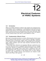
Figure 9.1
Mechanical two-phase refrigeration cycle.
frigeration utilizes thermocouples working in reverse: When an elec-
tric current is impressed on a thermocouple, a cooling effect is ob-
tained. These are small systems for specialized applications and are
comparatively expensive to install and operate.
9.2.1 The mechanical two-phase vapor
compression refrigeration cycle
The most common cooling source in HVAC is mechanical two-phase
vapor compression refrigeration. In this cycle (Fig. 9.1), a compressor
is used to raise the pressure of a refrigerant gas. Work energy (Q
W
)is
required, usually provided by an electric motor or steam turbine or
fuel-fired engine. The compression process raises the temperature of
the gas. The high-pressure gas flows through piping to a condenser
where heat is removed by transfer to a heat sink, usually water or air.
The refrigerant is selected with properties which allow it to condense
(liquefy) at the temperature and pressure in the condenser. The high-
pressure liquid is passed through a pressure-reducing device to the
evaporator. At the lower pressure, the liquid tends to evaporate, re-
moving the heat of vaporization (Q
C
) from its surroundings (the
Equipment: Part 1
Downloaded from Digital Engineering Library @ McGraw-Hill (www.digitalengineeringlibrary.com)
Copyright © 2004 The McGraw-Hill Companies. All rights reserved.
Any use is subject to the Terms of Use as given at the website.
Equipment: Part 1 289
evaporator—technically, the heat source). The cold, low-pressure va-
por is then returned to the compressor to be recycled. Note that the
heat removed in the condenser is equal to the sum Q
C
ϩ Q
W
. One index
of refrigeration cycle effectiveness is its coefficient of performance
(COP)
COP ϭ Q /Q (9.1)
CW
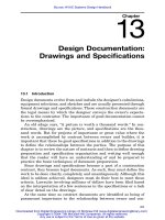
The refrigeration cycle can also be shown on a graph of the prop-
erties of a specific refrigerant. The graph in Fig. 9.2 is a pressure-
enthalpy or p-h diagram with the basic coordinates of pressure and
enthalpy. The four stages of the cycle include compression (with a rise
in temperature and enthalpy due to work done), condensing (cooling
and liquefying at constant pressure), expansion (at constant enthalpy)
and vaporization at constant pressure. The use of the p-h diagram
allows the selection of the most effective refrigerant for the pressures
and temperatures appropriate to the process. To minimize the work
energy required, the temperature difference between the heat source
and heat sink should be minimized.
9.2.2 Absorption refrigeration cycle
An absorption refrigeration cycle involves a refrigerant-absorbent pair,
where the refrigerant is moved from the low-pressure evaporator re-
gion to the high-pressure condensing region as an ‘‘absorbed’’ gas on
the back of the absorbent. Common refrigerant-absorbent pairs in-
clude ammonia-water and water–lithium bromide. In each case there
is a strong affinity of each compound for the other. Energy is given up
in the absorption process and energy is required to separate the pair.
As in vapor compression refrigeration, the beneficial cooling effect is
obtained from evaporation of the refrigerant in the low-pressure re-
gion of the system.
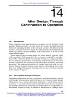
Figure 9.3 is a schematic diagram of a two-shell lithium bromide
water chiller using steam as the heat source. The saturated ‘‘strong’’
solution in the generator is heated to drive off water in vapor form.
The resulting unsaturated ‘‘weak’’ solution flows by gravity to the ab-
sorber, where the solution absorbs water vapor from the evaporator
and is then pumped back to the generator. The water driven off in the
generator is condensed in the condenser, flows by gravity to the evap-
orator and is evaporated there, with the heat of vaporization being
extracted from the chilled water. The condensing water is used first to
cool the solution in the absorber and then to condense the refrigerant
water. The evaporation and regeneration processes also create a pres-
sure differential between the upper and lower shell, and restrictors
Equipment: Part 1
Downloaded from Digital Engineering Library @ McGraw-Hill (www.digitalengineeringlibrary.com)
Copyright © 2004 The McGraw-Hill Companies. All rights reserved.
Any use is subject to the Terms of Use as given at the website.
290
Figure 9.2
Refrigeration cycle on pressure-enthalpy diagram for refrigerant-12.
Equipment: Part 1
Downloaded from Digital Engineering Library @ McGraw-Hill (www.digitalengineeringlibrary.com)
Copyright © 2004 The McGraw-Hill Companies. All rights reserved.
Any use is subject to the Terms of Use as given at the website.
Equipment: Part 1 291
Figure 9.3
Two-shell absorption refrigeration cycle.
(not shown) are used in the pipelines to help maintain this pressure
gradient. Heat rejection to the condensing water is roughly twice the
refrigeration effect. In addition to the heat supplied to the generator,
the chemical process of absorption creates some heat.
An absorption refrigeration system has a low coefficient of perform-
ance compared to a mechanical refrigeration system. Normally ab-
sorption can be justified economically only when plenty of compara-
tively low-cost or ‘‘waste’’ heat is available. Solar heat has been used,
although in most areas the cost of its collection makes solar energy
too expensive to compete with conventional fuels.
9.3 Compressors
In the refrigeration cycle, a compressor is a pump, providing the work
energy to move the refrigerant from the low-pressure region to the
Equipment: Part 1
Downloaded from Digital Engineering Library @ McGraw-Hill (www.digitalengineeringlibrary.com)
Copyright © 2004 The McGraw-Hill Companies. All rights reserved.
Any use is subject to the Terms of Use as given at the website.
292 Chapter Nine
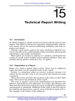
Figure 9.4
Reciprocating compressor.
high-pressure region through the system. Compressors come in two
general types: positive displacement and centrifugal. Positive displace-
ment compressors include reciprocating, rotary, scroll, and helical ro-
tary (screw) types.
9.3.1 Reciprocating compressors
Reciprocating compressors are usually the single-acting piston type.
Figure 9.4 shows one possible arrangement. The volume swept by the
piston is the displacement. The remaining volume under the cylinder
head is the clearance. The theoretical volumetric efficiency is a func-
tion of the ratio of these two volumes together with the compression
ratio of the system. Higher compression ratios result in lower volu-
metric efficiencies. The actual volumetric efficiency will be somewhat
less due to pressure drops across valves and other inefficiencies. The
capacity of the compressor is a function of the volumetric efficiency,
the properties of the refrigerant, and the operating pressures.
A compressor is always designed for a specific refrigerant at some
narrowly defined range of operating pressure.
A compressor may have from 1 to 12 cylinders. Some older machines
had as many as 24 cylinders. Most compressors for comfort cooling are
direct-driven by electric motors. Historically, compressors were belt-
driven, often by steam engines and at slow speeds.
Equipment: Part 1
Downloaded from Digital Engineering Library @ McGraw-Hill (www.digitalengineeringlibrary.com)
Copyright © 2004 The McGraw-Hill Companies. All rights reserved.
Any use is subject to the Terms of Use as given at the website.
Equipment: Part 1 293
Figure 9.5
Rolling piston-type
rotary compressor. (
SOURCE
:
Copyright 2000, American Soci-
ety of Heating, Refrigerating
and Air Conditioning Engineers,
Inc., www.ashrae.org. Reprinted
by permission from ASHRAE
Handbook, 2000 HVAC Systems
and Equipment, Chap. 34, Fig.
4.)
Sizes range up to as high as 200 tons or more in one compressor,
although units over 100 tons are rare. If larger capacities are needed,
two or more compressors are used in parallel. Small compressors—to
5or7
1
⁄
2
tons—are capacity-controlled by cycling the unit on and off.
Larger units usually have unloaders on all but one or two cylinders.
The unloader is activated electrically or pneumatically to lift the suc-
tion valve off its seat so that no compression takes place. Unloaders
may be activated in stages so that two or more steps of capacity control
may be obtained. Hot gas bypass is sometimes used with reciprocating
compressors to maintain stable operation at reduced loads. Hot gas
bypass does incur a power cost penalty.
Reciprocating compressors require from slightly less than 1 hp to
as much as 1.5 hp/ton of actual refrigeration capacity at the maximum
design temperatures and pressures typical of comfort-cooling pro-
cesses. The horsepower per ton increases as the suction pressure and
the temperature decrease. Therefore, it is more energy-efficient to op-
erate at the highest suction pressure compatible with the needs of the
application.
Compressors are lubricated by force-feed pumps or, in small units,
by splash distribution of oil from the sump. Lubricating oils are se-
lected to be miscible with the refrigerant and are carried throughout
the piping system, which must be designed to ensure return of the oil
to the compressor.
9.3.2 Rotary compressors
Rotary compressors are characterized by continuous circular or rotary
motion. The two common types are shown in Figs. 9.5 and 9.6. In the
Equipment: Part 1
Downloaded from Digital Engineering Library @ McGraw-Hill (www.digitalengineeringlibrary.com)
Copyright © 2004 The McGraw-Hill Companies. All rights reserved.
Any use is subject to the Terms of Use as given at the website.
294 Chapter Nine
Figure 9.6
Rotating-vane type of
rotary compressor. (
SOURCE
:
Copyright 2000, American Soci-
ety of Heating, Refrigerating
and Air Conditioning Engineers,
Inc., www.ashrae.org. Reprinted
by permission from ASHRAE
Handbook, 2000 HVAC Systems
and Equipment, Chap. 34, Fig.
7.)
rolling-piston type, the rotor turns on an eccentric shaft, continuously
sweeping a volume of space around the cylinder. Suction and discharge
ports are separated by a vane which slides in and out against the
cylinder wall. In the rotating-vane type of compressor, two sliding
vanes are mounted in the rotor to form a compression chamber. The
performances of the two types are similar.
In HVAC work, rotary compressors are seldom used in other than
small sizes, up to about 10-hp capacity. Unloaders are not used on
these small machines.
A special kind of rotary compressor has become prominent in the
marketplace—the scroll compressor. The compression element consists
of two interlocking spiral vanes, one stationary and the other rotating.
The vanes are arranged so that low-pressure gas enters at the periph-
ery and is compressed toward the center, where the gas flows out of
an annular discharge port. Some scroll compressor designs are able to
tolerate some liquid ‘‘slugging,’’ in contrast to positive displacement
compressors.
9.3.3 Helical rotary compressors
Helical rotary or screw compressors are made in single-screw and
twin-screw types. The single-screw compressor (Fig. 9.7) consists of a
helical main rotor with two star wheels. The enclosure of the main
rotor has two slots through which the star wheel teeth pass; these
teeth, together with the rotor and its enclosure, provide the bounda-
ries of the compression chambers. The twin-screw compressor (Fig.
9.8) has two meshing helical gears and works much as a gear pump,
with the helical shape forcing the gas to move in a direction parallel
to the rotor shaft. These machines typically are direct-driven at 3600
r/min and are usually oil-flooded for lubrication and to seal leakage
paths. Capacity control is obtained by means of a sliding or rotating
slotted valve.
Equipment: Part 1
Downloaded from Digital Engineering Library @ McGraw-Hill (www.digitalengineeringlibrary.com)
Copyright © 2004 The McGraw-Hill Companies. All rights reserved.
Any use is subject to the Terms of Use as given at the website.
Equipment: Part 1 295
Figure 9.7
Principle of operation
of a single-screw compressor.
(
SOURCE
: Copyright 1988, Amer-
ican Society of Heating, Refrig-
erating and Air Conditioning
Engineers, Inc., www.ashrae.
org. Reprinted by permission
from ASHRAE Handbook, 1988
Equipment, Chap. 12, Fig. 11.)
Figure 9.8
Helical rotary twin-
screw compressor. (
SOURCE
:
Copyright 2000, American Soci-
ety of Heating, Refrigerating
and Air Conditioning Engineers,
Inc., www.ashrae.org. Reprinted
by permission from ASHRAE
Handbook, 2000 HVAC Systems
and Equipment, Chap. 34, Fig.
24.)
9.3.4 Centrifugal compressors
Centrifugal compressors belong to the family of turbomachines, which
includes fans and centrifugal pumps. Pressures and flows result from
rotational forces. In HVAC work, these compressors are used primarily
in package chillers where the compressors provide large capacities.
Typical driven speed is 3600 r/min or more, using electric motor en-
gines or steam or gas turbines. Standard centrifugal chillers range in
capacity from 100 to 2000 tons, although some special units have been
built with capacities as great as 8500 tons. Capacity control is ob-
tained by varying the driven speed or by means of inlet vanes, similar
to those used on centrifugal fans. Noncondensing air-cycle systems,
such as used on commercial aircraft, use high-speed gas-turbine drives
at up to 90,000 r / min.
9.3.5 Hermetic compressors
Compressors may be built in either hermetic or open configurations.
A hermetic unit has a casing which encloses both the compressor and
the drive motor, minimizing the possibility of refrigerant leakage. Mo-
tors are specially constructed and are normally cooled with suction
gas or with liquid refrigerant. In an open machine, the drive motor or
turbine is separate from the compressor. Shaft seals must be provided
to prevent refrigerant leakage. Standard drives—direct, gear, or
Equipment: Part 1
Downloaded from Digital Engineering Library @ McGraw-Hill (www.digitalengineeringlibrary.com)
Copyright © 2004 The McGraw-Hill Companies. All rights reserved.
Any use is subject to the Terms of Use as given at the website.
296 Chapter Nine
Figure 9.9
Flooded liquid chiller.
belt—may be used. Semihermetic units have separate casings for the
compressor and the motor with matching flanges for gas-tight assem-
bly. Open drives have the advantage of removing the motor heat from
the refrigeration cycle, thereby improving chiller performance. This
advantage is lost if the motor heat is picked back up into the cooling
load indirectly.
9.4 Chillers
The term chiller is used in connection with a complete chiller
package—which includes the compressor, condenser, evaporator, in-
ternal piping, and controls—or for a liquid chiller (evaporator) only,
where the water or brine is cooled.
Liquid chillers come in two general types: flooded and direct-
expansion. There are several different configurations: shell-and-tube,
double-tube, shell-and-coil, Baudelot (plate-type), and tank with race-
way. For HVAC applications, the shell-and-tube configuration is most
common.
9.4.1 Flooded chillers
A typical flooded shell-and-tube liquid chiller is shown in Fig. 9.9.
Refrigerant flow to the shell is controlled by a high- or low-side float
valve or by a restrictor. The water flow rate through the tubes is de-
fined by the manufacturer but it generally ranges from 6 to 12 ft/s.
Tubes may be plain (bare) or have a finned surface. The two-pass ar-
rangement shown is most common, although one to four passes are
available. The chiller must be arranged with removable water boxes
so that the tubes may be cleaned at regular intervals, because even a
Equipment: Part 1
Downloaded from Digital Engineering Library @ McGraw-Hill (www.digitalengineeringlibrary.com)
Copyright © 2004 The McGraw-Hill Companies. All rights reserved.
Any use is subject to the Terms of Use as given at the website.
Equipment: Part 1 297
Figure 9.10
Direct-expansion chiller (U-tube type).
small amount of fouling can cause a significant decrease in the heat
exchange capacity. The condenser water tubes are especially subject
to fouling with an open cooling tower. Piping must be arranged to
allow easy removal of the water boxes.
9.4.2 Direct expansion (DX) chillers
In the DX liquid chiller (Fig. 9.10), the refrigerant is usually inside
the tubes with the liquid in the shell. Baffles are provided to control
the liquid flow. The U tube configuration shown is typical and less
expensive than the straight-through tube arrangement but can lead
to problems with oil accumulation in the tubes if refrigerant velocities
are too low. Refrigerant flow is controlled by a thermal expansion
valve.
9.4.3 Package chillers
A complete package chiller will include compressor, condenser, evap-
orator (chiller), internal piping, and operating and capacity controls.
Controls should be in a panel and include all internal wiring with a
terminal strip for external wiring connections. In small packages—up
to about 250 tons—motor starters are usually included. In larger chill-
ers, unit-mounted starters are an option. Some units with air-cooled
condensers are designed for outdoor mounting; freeze prevention pro-
cedures must be followed. Units with water-cooled condensers require
an external source of condensing water.
Chillers with reciprocating compressors are found mostly in the 5-
to 200-ton range. Although larger units are made, economics usually
Equipment: Part 1
Downloaded from Digital Engineering Library @ McGraw-Hill (www.digitalengineeringlibrary.com)
Copyright © 2004 The McGraw-Hill Companies. All rights reserved.
Any use is subject to the Terms of Use as given at the website.
298 Chapter Nine
favor centrifugal compressor or screw chillers, in sizes of 150 tons or
more. Screw compressor systems are made in a wide range of sizes,
by a growing number of manufacturers. With larger chillers or with
high-voltage motors (2300 V, 4160 V), motor starters are usually sep-
arate from the centrifugal or screw chiller mounting frame and require
field wiring of power and control circuits. Centrifugal compressor
packages may be turbine-driven, occasionally engine-driven, but most
often are driven by electric motors. The typical system is direct-driven
at 3600 r/min. Wye-delta motors are often used for reduced-voltage
starting. Electronic ‘‘soft-start’’ devices are now available. Variable-
speed controllers are inherently soft starting. In larger units of 1000
tons or more, it is not unusual to use high-voltage motors; the lower
current requirements allow smaller wire sizes and across-the-line
starting. An unusual drive system evolved on one of the 8500-ton chill-
ers at a major international airport. The utility plant manager re-
placed an original steam-turbine driver with a 5000-hp 4160-V vari-
able-speed, variable-frequency electric drive. The chiller capacity was
reduced to 5500 tons, more in line with the actual load.
9.5 Condensers
The purpose of the condenser in a two-phase refrigeration cycle is to
cool and condense the hot refrigerant gas leaving the compressor dis-
charge. It is, then, a heat exchanger, of the shell-and-tube, tube-and-
fin, or evaporative type. The heat sink is air, water, or a process liquid.
Typically, small package systems use air-cooled condensers. Large
built-up systems use water-cooled or evaporative condensers, although
large air-cooled condensers are sometimes employed. The contrasting
criteria here are the lower first cost of air-cooled condensers compared
with the improved efficiencies obtained with water-cooled or evapo-
rative condensers. The improvement in efficiency comes about because
of the lower condensing temperatures achieved with water-cooled or
evaporative condensers. The condenser capacity should match as
closely as possible the capacity of the compressor in the system, al-
though oversizing is preferable to undersizing if compressor efficiency
is to be maximized.
9.5.1 Air-cooled condensers
An air-cooled condenser is usually of the finned-tube type (Fig. 9.11),
with the refrigerant in the tubes and air forced over the outside of the
tubes and fins by a fan. Capacity control, if used, is accomplished by
cycling the fan, using a multispeed fan, or modulating airflow by
means of dampers. Refrigerant flow velocities must be designed to
prevent oil traps in the tubes. Capacities are based on square feet of
Equipment: Part 1
Downloaded from Digital Engineering Library @ McGraw-Hill (www.digitalengineeringlibrary.com)
Copyright © 2004 The McGraw-Hill Companies. All rights reserved.
Any use is subject to the Terms of Use as given at the website.
Equipment: Part 1 299
Air in
Air out
Liquid out
Hot gas in
Condenser coil
Screen
Figure 9.11
Air-cooled condenser.
coil face area, fan airflow rate, desired condensing temperature, and
design ambient dry-bulb (db) temperature. Note that at reduced am-
bient temperatures, performance of air-cooled condensers improves;
sometimes approaching the seasonal performance of water-cooled sys-
tems.
9.5.2 Water-cooled condensers
Water-cooled condensers are typically of the shell-and-tube type, with
the water in the tubes and the refrigerant in the shell (Fig. 9.12).
Chiller capacity control is not normally related to condenser water
temperature. However, the water temperature may vary if it is sup-
plied from a cooling tower, and most chiller manufacturers prefer that
condensing water not be taken below 65 to 70ЊF because the oil may
get held up in the condenser. Most code authorities do not allow direct
use (and waste) of domestic water for condensing purposes.
9.5.3 Evaporative condensers
An evaporative condenser (Fig. 9.13) includes a bare (no fins) tube coil
which contains the refrigerant, a system for spraying water over the
coil, a ‘‘casing’’ enclosure around coil and sprays, and a fan to force or
draw air through the enclosure across the coil and sprays. The spray
system includes a sump with a float valve for makeup water and a
Equipment: Part 1
Downloaded from Digital Engineering Library @ McGraw-Hill (www.digitalengineeringlibrary.com)
Copyright © 2004 The McGraw-Hill Companies. All rights reserved.
Any use is subject to the Terms of Use as given at the website.