Cảm biến trong sản xuất P15
Bạn đang xem bản rút gọn của tài liệu. Xem và tải ngay bản đầy đủ của tài liệu tại đây (419.93 KB, 19 trang )
307
70
Chen, S. B., Wu, L., Wang, L., Liu, Y.
C., Weld. J. (Miami) 76 (1997) 201–209.
71
Eguchi, K., Yamane, S., Sugi, H., Kubo-
ta, T., Oshima, K., in: Proceedings of the
24th Annual Conference of the IEEE Indus-
trial Electronics Society, Aachen, 31 Au-
gust–4 September 1998, pp. 1182–1185.
72
Drews, P., Wagner, R., Willms, K.,
VDI-Z. (2) (1991) 88–92.
73
Suga, Y., Mukai, M., Usui, S., Ogawa,
K., in: Proceedings of the Seventh Interna-
tional Offshore and Polar Engineering Con-
ference, Honolulu, HI, 25–30 May 1997,
pp. 502–507.
74
Kovacevic, R., Zhang, Y. M., Proc. Inst.
Mech. Eng., Part B: J. Eng. Manuf. 210
(1996) 553–564.
75
Sun; A., Kannatey-Asibu, Jr., E., Gart-
ner, M., J. Laser Appl. 11 (1999) 153–168.
76
Kogel-Hollacher, M., Jurca, M., Dietz,
C., in: Proceedings of ICALEO 98, Orlan-
do, FL, Vol. 85, 1998, pp. 168–177.
77
Müller, M., Dausinger, F., Hügel, H.,
in: Proceedings of ICALEO 98, Orlando,
FL, Vol. 85, 1998, pp. 122–132.
78
Tönshoff, H. K., Schumacher, J., in:
Proceedings of ICALEO 96, Detroit, MI,
1996, pp. 45–54.
79
Tönshoff, H. K., von Alvensleben, F.,
Ostendorf, A., Güttler, R., in: Proceed-
ings of ICALEO 98, Orlando, FL, Vol. 85,
1998, pp. 78–85.
80
Ricciardi, G., Cantelle, M., Mariotti,
F., Castello, P., Panesa, M., Ann. CIRP
48 (1999) 159–162.
81
Chin, B. A., Zee, R. H., Wikle, H. C., J.
Mater. Process. Technol. 89–90 (1999) 254–
259.
82
Chin, B. A., Wikle, H. C., Chen, F., Na-
garajan, S., J. Chin. Inst. Eng. 21 (1998)
645–657.
83
Matthes, K.-J., Herrich, J., Lindner,
D., Drews, P., Benz, S., Matzner, D.,
Schweissen Schneiden 49 (1997) 170–174.
84
Dilthey, U., Pavlenko, A., Ellermeier,
J., Schweissen Schneiden 48 (1996) 227–
230.
85
Bouaifi, B., Günster, J., Hillebrecht,
M., DVS-Ber. 176 (1996) 117–120.
4.8
Coating Processes
K.-D. Bouzakis, N. Vidakis, Aristoteles University of Thessaloniki, Thessaloniki, Greece
G. Erkens, CemeCon GmbH, Würselen, Germany
4.8.1
Coating Process Monitoring
4.8.1.1
Introduction
One of the most promising, generally applicable and well-adopted methods to en-
hance the surface performance of materials is the use of coatings. The reason is
that it is extremely difficult and expensive to meet homogeneous materials having
on their surface the ensemble of desired properties, such as high hardness, wear
resistance, adequate stiffness, increased ductility, chemical inertness, stainless-
ness, controllable electrical and thermal conductivity behavior, etc. Some of the
aforementioned properties are contradictory to each other and it is impossible to
achieve them simultaneously [1–3]. Surface coatings nowadays offer a satisfactory
reliable and economical alternative solution to this problem. There are several
methods to deposit surface films, based on a variety of physical, chemical, and
thermal processes and transformations, taking into account also the substrate
material specifications and the duty of the element or tool to be coated.
Sensors in Manufacturing. Edited by H.K. Tönshoff, I. Inasaki
Copyright © 2001 Wiley-VCH Verlag GmbH
ISBNs: 3-527-29558-5 (Hardcover); 3-527-60002-7 (Electronic)
Coating methods have rapidly gained a significant part of material technology
in a variety of application fields. To quantify this fact, the estimated market share
of the coated tools was approximately 95% at the end of the 1990s [4]. On the
other hand, coatings play an important role in electronics and engineering. Tradi-
tional machine elements, such as bearings, gears, etc., are nowadays a major field
for research and development for the coatings industry. The doubtless profitable
results of the coatings applications led to the development of flexible and sophisti-
cated deposition processes that today offer mono- and multilayer, structural, or
compositional films, with excellent mechanical, physical, and chemical properties,
but consequently increased the complexity of the corresponding coating deposi-
tion equipment.
Coating processes are exceptionally multiparametric functions, so that their
successful progress and completion require a strict but flexible monitoring and
control system [5, 6]. Even the simplest deposition methods involve more than
two parameters that have to be tracked throughout the process, in order to estab-
lish the required coating properties. Furthermore, as will be described below, the
wide variation of applicable coating strategies sets their control, case dependent.
Considering that an optimized deposition process is a consequence of the proper
selection of the values for all influencing parameters, deposition monitoring has
to be integrated and inclusive.
4.8.1.2
Vacuum Coating Process Classification
The most popular and well-adopted deposition methods are based on vapor trans-
formations and more specifically on physical (PVD) and chemical vapor deposi-
tion (CVD) [7]. On the other hand, both of them, especially the former, are the
most multi-parametric and sensitive methods, thus demanding strict monitoring
and control. Therefore, in the frame of the scope of this section, the sensors re-
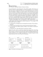
quired for PVD and CVD processes are presented. Figure 4.8-1 illustrates a rough
classification of these deposition strategies, which are even more subdivided, con-
sidering the design principles of the corresponding installation manufacturers.
The PVD method consists in removing metallic ions from a target, forming a
plasma environment, and making them react with a gas to form a ceramic com-
pound, which is deposited on the surface of the product, called the substrate.
Thereby, the deposition species are atoms or molecules or a combination of them.
The deposition is effected by condensation, exothermic, and makes extensive use
of plasmas. The deposition is performed in a high-vacuum chamber, and the de-
position temperatures vary from 150 to 500 8C [1, 8]. The PVD method is very flex-
ible, and offers a variety of single and multilayer coatings (structural or composi-
tional), covering a wide range of physical, chemical, and electrical properties of
the film deposited.
In a typical CVD process, reactant gases at room temperature enter a tight reac-
tion chamber. The gas mixture is heated as it approaches the deposition surface,
heated radiatively, or placed upon a heated substrate. The CVD method is per-
formed at higher temperatures, > 850 8C [1]. Depending on the process and operat-
4 Sensors for Process Monitoring308
ing conditions, the reactant gases may undergo homogeneous chemical reactions
in the vapor phase before striking the surface. Near the surface thermal, momen-
tum, and chemical concentration boundary layers form as the gas stream heats,
slows owing to viscous drag, and the chemical composition changes. Hetero-
geneous reactions of the source gases or reactive intermediate species, formed
from homogeneous pyrolysis, occur at the deposition surface forming the depos-
ited material. Gaseous reaction by-products are then transported out of the reac-
tion chamber. Traditional applications of the CVD method, such as the production
of coated tools, are being progressively replaced by the PVD method, owing to its
flexibility and significantly lower deposition temperatures.
4.8.1.3
Vacuum Coating Process Parameter Monitoring Requirements
As in any other multi-parametric process, there are two main categories of sens-
ing systems that are involved. The first focuses on the run-in phase and includes
testing and calibration of the coating device. In this respect, these control systems
are used by the research and development and also by the maintenance divisions
of coating device producers and research institutes. For these reasons, the equip-
ment utilized is removable, complicated, and expensive, whereas it orients the
state of the art in coating process sensing systems. The second category includes
fixed sensing systems that are steadily implemented with the coating device and
are necessary to monitor the progress of the coating process by the coating pro-
ducers, ie, the end users of such devices. The first group of sensing systems en-
sures that the coating device is well constructed and standardized, whereas the
second group makes certain of the quality of the final product, ie, of the coated
part. In this section, both sensing system types will be presented with respect to
each deposition method.
4.8 Coating Processes 309
Fig. 4.8-1
Classification of vapor deposition processes
Sputter Ion
Plating (HF/DC)
In situ coating process monitoring follows the same fundamental rules as every
other automated controlled system. With respect to the importance of the parame-
ter to be monitored and the possibility of adjusting it, in order to optimize the
coating process, open- or closed-loop control systems can be designed. Hence
there are parameters that have to be continuously checked but not adjusted,
whereas others may be integrated in feedback systems and be adjusted through-
out the deposition course. The principles of adaptive control find a wide range of
applications in this last group of process parameters. In every case, coating pro-
cesses are very sensitive to any deposition parameter modification, even transient,
considering the restricted film thickness and its refined properties. Therefore,
every sensing system involved must have increased resolution, accuracy, repeat-
ability and reliability. These requirements concern the sensors, the electronic de-
vices, and the evaluation tools of the measured magnitudes, which compose the
sensing systems.
A further important parameter that must be considered by device producers is
to ensure that sensors are coated without reducing their sensitivity. For this pur-
pose, process sensors are protected, when necessary, by special filters or ion traps,
which are considered as process spare parts. On the other hand, there are sen-
sors, such as quartz crystals for deposition rate monitoring, which modify their in-
dications as they are progressively coated. Therefore, they must be replaced at the
termination of each specific coating process, in order to monitor the course of the
consequent deposition process.
Coating process parameters are monitored during the deposition with the aid of
various types of sensors. A distinctive classification of them is with regard to their
output, ie, whether they produce analog or digital signals. Both types are used in
coating technology and for the same measurable parameter analog or digital sen-
sors may be applied. Nowadays, advanced data acquisition systems are computer
supported and may handle either analog or digital signals. In the first case, ana-
log to digital converters (usually A/D cards) are utilized to let the digital hardware
tools evaluate and control the input measurements. These electronic circuits must
also satisfy the demands of the whole sensing system.
To simplify the coating process control further, advanced and powerful software
tools are exploited today in order to visualize the deposition progress. Coating de-
vice producers support their customers with exclusive programs that electronically
and remotely control the deposition process. For this purpose they develop soft-
ware using modern programming languages in Windows
®
environments, or
using existing platforms, such as the LabView
®
code. In every case, these pro-
grams offer visual environments for data acquisition, alerts, parameter adjust-
ment, and reports of the whole process.
4 Sensors for Process Monitoring310
4.8.2
Sensors in Vapor Deposition Processes
4.8.2.1
Vapor Process Parameter Map
Physical and chemical deposition methods have various common parameters to
be monitored, although the first ones are more complicated and multi-parametric.
Therefore, shared parameters and magnitudes are controlled by sensors based on
the same principle, whereas their measuring range is suitably adjusted or modi-
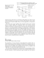
fied. Figure 4.8-2 illustrates the parameters that influence the deposition pro-
cesses and therefore must be controlled, for either development or quality control
purposes. In addition to the measuring parameter, Figure 4.8-2 summarizes the
sensor type per case and their measuring range. It can be seen that it is possible
to monitor different parameters using the same sensor type, as will be described
more analytically below.
4.8.2.2
Vacuum Control
The required high vacuum, for vapor coating processes, is accomplished by
means of medium- or high-vacuum equipment and process instrumentation
(chamber pressure <10
–4
Torr). The pressure must held under control in situ, ie,
during the process, and therefore pressure modifications or leaks are completely
inadmissible and must be rapidly detectable. Vacuum control covers two stages.
4.8 Coating Processes 311
Fig. 4.8-2
Influencing parameters and sensors for their monitoring in vapor deposition pro-
cesses
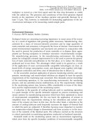
The first covers the vacuum formation itself at the beginning of the coating pro-
cess, whereas the second aims to maintain the pressure stable, also while the pro-
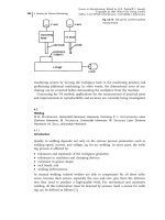
cess gases are flowing into the deposition chamber [9, 10] (see Figure 4.8-3).
These requirements are accomplished by designing special gas flow systems, con-
sisting of vacuum fitments, pipelines, and valves, which are properly controlled by
special hardware and software tools.
There are several approaches to vacuum monitoring and control during the
PVD process. Measurement of pressure in a vacuum system is done with any of a
variety of gages, which for the most part work through somewhat indirect means,
eg, thermal conductivity of the gas or the electrical properties of the gas when ion-
ized. The former are typically used at higher pressures (1–10
–3
Torr) and the latter
in lower ranges. Such gages are sensitive to the type of gas in the system, requir-
ing that corrections be made. Accidents have occurred when this was not taken
into account. For example, the presence of argon in a system will result in a pres-
sure reading on a thermal conductivity gage (thermocouple or Pirani, for exam-
ple, as described in the next two sections) that is much lower than the true pres-
sure. It is possible to overpressure a system significantly while the gage is still in-
dicating vacuum. Other indirect vacuum measurements are based on partial pres-
sure determination, ie, through mass spectrometry.
Actually, there is no universal gage that can measure from atmospheric to ultra-
high vacuum pressure. Therefore, the instrument chosen depends on the pres-
sure range and the residual gases in the vacuum. In any case, pressure measure-
ments may be either output sensor signals to be further processed by open- or
closed-loop control units or direct indications in special displays. The only solu-
tion for a single pressure gage covering a wide measurement range is by combin-
ing more than three probes in one control system.
4 Sensors for Process Monitoring312
Fig. 4.8-3
Vacuum monitoring initially and during the coating process
4.8.2.2.1
Thermocouples
Thermocouple vacuum gages offer an economical method of vacuum pressure
measurement with accuracy suitable for many monitoring and control applica-
tions and general laboratory use. Simplicity of operation, low cost, and the inher-
ent ruggedness of these gages have led to their widespread general use with time-
proven dependability and zero maintenance. The pressure range between 10 and
10
–3
Torr is indicated by measuring the voltage of a thermocouple, spot-welded to
a filament exposed to vacuum system gas (see Figure 4.8-4). This filament is fed
from a constant current supply, and its temperature depends on the thermal
losses to the gas. At higher pressures, more molecules hit the filament and re-
move more heat energy, causing the thermocouple voltage to change. These sen-
sors are used extensively in foreline monitoring and to provide the trigger signal
to switch automatically the main chamber from backing. The pressure indications
of thermocouples, as already mentioned, are gas-type dependent.
4.8.2.2.2
Pirani Gages
Pirani gages for medium-vacuum monitoring are usually utilized in PVD installa-
tions and their indications are also dependent on gas type. Pirani gages operate
on the principle that the thermal conductivity of gas is proportional to the num-
ber of residual gas molecules, ie, the pressure. The operating principle of Pirani
gages is illustrated in Figure 4.8-5. Two filaments, often made of platinum, are
used as resistances in two arms of a Wheatstone bridge. The reference filament is
immersed in a gas at fixed pressure, whereas the measurement filament is ex-
posed to the vacuum system gas. Both filaments are heated by the current, pass-
ing through the bridge. Thereby, gas molecules conduct heat away from the im-
mersed element and inbalance the bridge. Their measuring range is from 10
–3
up
to 1 Torr. In most cases, these vacuum sensors produce output signals that may
4.8 Coating Processes 313
Fig. 4.8-4
Thermocouple gage for vacuum monitoring (sensor by A-VAC)