Cảm biến trong sản xuất P16
Bạn đang xem bản rút gọn của tài liệu. Xem và tải ngay bản đầy đủ của tài liệu tại đây (282.53 KB, 17 trang )
4.9
Heat Treatment
P. Mayr, H. Klümper-Westkamp, Stiftung Institut für Werkstofftechnik IWT, Bremen,
Germany
4.9.1
Introduction
After mechanical manufacturing, heat treatment is mainly applied in one of the
final steps of production, to adjust the workpiece properties to the later mechani-
cal, tribological, and corrosive load. The lifetime of these components is defined
through the raw material used, the construction geometries, and the quality of
heat treatment.
The great demands for quality control and the documentation of process param-
eters have led to the increasing importance of sensor applications in heat treat-
ment. Furthermore, increasing automation combined with the idea of integrating
the heat treatment into the production line needs many different sensors to make
the whole process as reliable as possible.
4.9.2
Temperature Monitoring
The primary process variable to be measured and controlled in heat treatment is
the temperature, which directly influences component properties. There are a very
large number of different temperature-dependent physical properties that can
serve, at least in principle, as the basis for thermal sensors. Only a few of them
are used in heat treatment plants to measure the temperature.
Thermocouples are the most commonly used temperature sensors in heat treat-
ment. They consist of two conductors of different metallurgical composition,
which are made up into an electrical circuit with two junctions. If the two junc-
tions are brought to a different temperature, a thermoelectric potential is created.
The magnitude depends on the composition of the conductors chosen and the
temperature difference [1].
Their simple construction allows sensors to be made which are able to provide
reliable and accurate data under extreme measurement conditions. With thermo-
couples a range from –270 to 2000 8C can be covered, depending on the material
used. The accuracy depends on the temperature being measured and ranges from
0.1 K at room temperature to ± 10 K at very high temperature. The characteristics
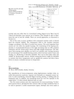
of various commonly used thermocouples are illustrated in Figure 4.9-1. Interna-
tional, eg, IEC 584, and national standards, eg, DIN 43710 in Germany, have been
set up. NiCr-Ni is the most frequently employed thermocouple in industrial plants
up to 1100 8C. In most applications they are sheathed. The thermocouple wires
are embedded in an isolating powder (eg, MgO, Al
2
O
3
) and surrounded by a me-
tal sheet (eg, Inconel, stainless steel). At higher temperatures, PtRh-Pt thermocou-
ples are used. They should be protected by ceramic tubes [2].
4 Sensors for Process Monitoring326
Sensors in Manufacturing. Edited by H.K. Tönshoff, I. Inasaki
Copyright © 2001 Wiley-VCH Verlag GmbH
ISBNs: 3-527-29558-5 (Hardcover); 3-527-60002-7 (Electronic)
According to Planck’s law, the spectral radiation of a blackbody at a particular
wavelength varies only with the blackbody temperature. The optical pyrometer
makes use of this principle by measuring ratios of spectral radiances. The radia-
tion characteristic of a blackbody is shown in Figure 4.9-2. The wavelength spec-
trum utilized for radiation thermometers usually lies between 0.5 and 20 lm. The
use of radiation thermometers is simple when dealing with surfaces showing
blackbody condition. Unfortunately, in most applications deviations from black-
4.9 Heat Treatment 327
Fig. 4.9-1
Thermal emfs of commonly used thermocouples [2]
Fig. 4.9-2
Characteristic radiation of a blackbody [3]
10
4
Wcm
±2
l
m
±1
sr
±1
Spectral radiance L
k S
10
3
10
2
10
1
10
0
10
±1
10
±2
10
±3
10
±4
10
±5
6000 K
3000 K
1000 K
500 K
300 K
200 K
0.1 0.2 0.4 0.6 1 2 4 6 10 20 40
l
m 100
Wavelength k
body condition occur as a result of absorption, emissivity, and reflection effects.
The most difficult problems arise with unknown and variable emissivity.
Optical pyrometers can be subdivided into four groups depending on the wave-
length and wavebands used:
· total-radiation thermometers;
· single-waveband thermometers;
· ratio thermometers;
· multi-waveband thermometers.
The very common single-waveband thermometers with silicon or germanium de-
tectors use short wavelengths between 0.5 and 2 lm. For very low temperatures
longer wavelengths are used because of a higher rate of change of energy with
temperature. Ratio thermometers measure the ratio of energy in two narrow wave-
bands. The advantage is that their readings will be independent of target size, ob-
scurity of optical path, and emissivity, provided that they are the same at the two
wavelengths [2].
The electric resistance of some metals increases with increase in temperature in
a nearly linear fashion. This property has been applied for temperature measure-
ment. Platinum is the most precious metal used for thermometry. Platinum can
be drawn in to very thin wires of high purity. Thick- and thin-film sensors are
also available.
Ruggedness and relatively low costs are combined in platinum thick-film ther-
mometers. They are used in industrial applications up to 450 8C when encased in
ceramic, glass, or other protective materials. Atmospheres containing carbon or
hydrogen are poisonous for platinum and lead to unstable resistance. Resistance
thermometers have the advantage of high accuracy measurement. Typically, a tem-
perature resolution of ± 10
–3
8C can be achieved up to 500 8C whereas thermocou-
ples are limited to ± 0.5 8C. Special geometries are available for surface tempera-
ture measurement.
In special applications other metals such as copper, nickel, and iridium are
used [2].
A number of physical effects have been checked to realize fiber-optic temperature
sensors [4]. The main fiber-optic thermometers today use the temperature depen-
dence of the fluorescence decay time. This effect has been utilized in commercial
instruments by Luxtron and Sensycon. The main advantage of this temperature
measurement method is the capability to allow measurements in severely hostile
environments. They can be made in the presence of intense radiofrequency and mi-
crowave fields as well as very high voltages and strong magnetic fields. In the range
from –200 to 450 8C, an accuracy of ± 0.1 8C can be reached at the calibration point.
In continuously working furnaces, temperature measurements can be made by
furnace tracker systems. A data logger for thermocouples is positioned in a ther-
mal protection unit made of inert and maintenance-free material. During the fur-
nace travel the data logger stores the measured temperatures, which can be read
later. Such a furnace tracker works up to temperatures of 1200 8C. Such systems
have been developed and are sold by DATAPRO and Stoppenbrink.
4 Sensors for Process Monitoring328
4.9.3
Control of Atmospheres
Heat treatment is done, depending on the aim of the treatment, in different fur-
naces with different pressures, atmospheres, and plasma application. The scale in
pressure ranges from vacuum up to high pressures of several hundred bar. De-
pending on the aim of heat treatment, different gases and gas mixtures are ap-
plied. When there are no requirements on the workpiece surface, heat treatment
can be done in air, which means that oxidation takes place during heat treatment.
To avoid this oxidation, inert atmospheres with low oxygen partial pressure must
be used and controlled.
Another group of processes is the thermochemical heat treatment processes.
The purpose is to modify the workpiece by specific reactive atmospheres, so that
carbon (carburizing) and/or nitrogen (nitriding) diffuses into the near-surface re-
gion and parallel oxidation can take place at the surface. To control the oxygen
partial pressure, the oxygen probe was the first developed in situ sensor in ther-
mochemical heat treatment. With the knowledge of the oxygen partial pressure,
many other process parameters can be evaluated. Some different constructions of
oxygen probes are discussed in [5].
4.9.4
Carburizing
For controlling the carburizing process, the chemical equilibrium between the car-
burizing gas and steel is used. Under the assumption of unchanged basic compo-
nents CO and H
2
, the simplified value ‘CO
2
’ or ‘dew point’ is derived, which is
the main controlled variable for the carbon potential.
It has been well established for more than 25 years that the partial pressure of
oxygen measured by oxygen probes [6] can be used as an exact indicator of the
carbon potential. This permits considerable progress with regard to accuracy, re-
sponsiveness, reproducibility, and technical handling, so that this sensor is being
increasingly used.
The basic principle is an oxygen ion-conducting electrochemical cell of stabi-
lized ZrO
2
. The measured potential E depends on the difference in oxygen partial
pressure P
O
2
at the two electrodes. P
0
O
2
is the known reference oxygen pressure,
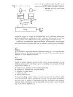
normally of air. In Figure 4.9-3 a schematic diagram of such a sensor is shown.
The temperature T is measured in kelvin [7].
E mV0:0496 T logP
O
2
=P
0
O
2
4:9-1
In oxygen-containing carburizing atmospheres, the following chemical reaction is
the main indicator for the carburizing reaction:
CO C
1
2
O
2
4:9-2
4.9 Heat Treatment 329
Under the assumption of thermodynamic equilibrium, the carbon activity a
c
is
given by
log a
c
logP
CO
=P
O
2
0:5
À5927=T À 4:545 4:9-3
With known pressure of carbon monoxide P
CO
and temperature T, the carbon
activity can be calculated from the measured oxygen partial pressure. The carbon
activity of the carburizing atmosphere defines the dissolved carbon in austenite
under the assumption of thermodynamic equilibrium. More information about
oxygen-free carburizing atmospheres can be found in [7].
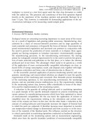
A further innovation is the application of oxygen probes in heat treatment, pri-
marily known from automobiles for measuring the lambda point of combustion.
When they are used in heat treatment plants they are normally located outside
the furnace and measure the oxygen partial pressure on the basis of an electro-
chemical unit at temperatures around 500 8C. The measured value has to be recal-
culated to the furnace temperature and additionally it should be mentioned that
owing to the outside mounting, more uncontrolled influences can change the
value. As the measured oxygen potential can be regarded in most cases as integral
information for the whole furnace, this system can also be useful for controlling
the degree of sealing of the furnace. Because of the mass production of this lamb-
da probe it is much cheaper but in many applications not as reliable as the stan-
dard in situ oxygen probe.
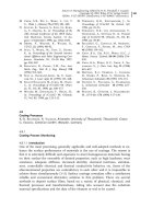
A direct method for measuring the carbon uptake in almost every atmosphere
is the so-called wire sensor [8]. This sensor is based on the resistivity change of a
thin, pure iron wire with increasing amount of dissolved carbon, as shown in Fig-
4 Sensors for Process Monitoring330
Fig. 4.9-3
Mode of action of an oxygen probe [7]
ure 4.9-4. Periodically the wire is decarburized with hydrogen so that it can be
used again. This in situ sensor is mostly applied for periodic checking of the abso-
lute carbon potential in furnaces. Continuous control of the carbon potential in a
furnace is not practicable because of problems with oxidation, formation of car-
bides, and changing surface of the wire. This in situ sensor is sold by Process-
Electronic.
4.9.5
Nitriding
Gas nitriding is usually carried out in ammonia-containing atmospheres. Since
Lehrer’s paper [9], it is known that the nitriding potential K
N
is the driving force
of nitriding and defines the phase composition of the white layer. The nitriding
potential K
N
is defined by the well-known ratio of the partial pressures of ammo-
nia, P
NH
3
, and hydrogen, P
H
2
:
2NH
3
N
2
3H
2
4:9-4
K
N
P
NH
3
=P
H
2
0:5
4:9-5
In the case when pure decomposition of ammonia dominates the nitriding pro-
cess, this nitriding potential presents a reliable indicator for the nitriding process.
In nitriding atmospheres little is known about the basic level of the partial pres-
sure of oxygen. Established process control have used external gas analyzers based
on infrared absorption or heat conduction for many years. Recently, in situ sen-
sors have been developed which are able to measure directly the nitriding poten-
tial inside the furnace. They are based on oxygen probes containing a solid elec-
trolyte of stabilized zirconia. The experimental approach to measuring the nitrid-
ing potential with oxygen probes is different to that for the control of the carbon
4.9 Heat Treatment 331
Fig. 4.9-4
Probe tip of the wire sensor (Werkfoto PE-Essen)