HVAC Systems Design Handbook part 11
Bạn đang xem bản rút gọn của tài liệu. Xem và tải ngay bản đầy đủ của tài liệu tại đây (260.49 KB, 30 trang )
367
Chapter
11
Equipment: Part 3
Air-Handling Systems
11.1 Introduction
By definition, air conditioning involves control of the air temperature,
humidity, cleanliness, and distribution. It follows that an air-handling
unit (AHU) of some kind is an essential part of an air conditioning
system, though not necessarily of a heating-only system.
The function of the AHU is to provide air at a quantity, temperature,
and humidity to offset the sensible and latent heat gains to the space
(in the cooling mode) and the heat losses (in the heating mode), while
maintaining the required temperature and humidity in the space. This
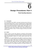
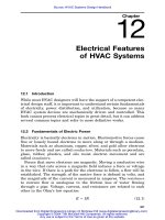
can be most clearly shown on a psychrometric chart (Fig. 11.1). A
typical cooling design room condition is 78ЊF dry-bulb (db) tempera-
ture and 50 percent RH. For illustration, a load of 120,000 Btu/h sen-
sible and 30,000 Btu/h latent cooling is assumed. Then, for an as-
sumed 20ЊF temperature difference between the room and supply air
temperatures (58ЊF supply air), the design flow rate of air, designated
CFM, in cubic feet per minute (cfm) will be
120,000
3
CFM ϭϭ5555 ft /min (cfm) (11.1)
20 ϫ 1.08
where 1.08 is the air factor in Btu/h, cfm, ЊF.
The change in specific humidity ⌬w may be calculated as follows:
3
1min 1ft 1h 1lb
w
⌬w ϭ 30,000 Btu/h ϫϫ ϫϫ
3
5555 ft 0.075 lb 60 min 1059 Btu
a
ϭ 0.0011 lb /lb (11.2)
wa
Source: HVAC Systems Design Handbook
Downloaded from Digital Engineering Library @ McGraw-Hill (www.digitalengineeringlibrary.com)
Copyright © 2004 The McGraw-Hill Companies. All rights reserved.
Any use is subject to the Terms of Use as given at the website.
368 Chapter Eleven
Figure 11.1
Psychrometric chart for draw-through air conditioning process.
The point defined by these two differential values can be plotted on
the chart, as shown. The ‘‘validity’’ of this point must be verified, based
on the cooling coil capability and the AHU arrangement, as discussed
in Sec. 3.6. For a draw-through arrangement (i.e., with the supply fan
downstream of the cooling coil), the supply air temperature will be
greater than the coil leaving temperature because of heat added by
fan work. For this example, if 5 hp is required, the temperature dif-
ference (TD) will be
2545 Btu 1
TD ϭ 5hpϫϫ
3
1hp⅐ h 5555 ft /min
3
1h⅐ (ft / min) ⅐ ЊF
ϫϭ2.1ЊF (11.3)
1.08 Btu
Then a coil leaving condition of 55.9ЊF db and 55.5ЊF wb can be plot-
ted, and this will probably be valid.
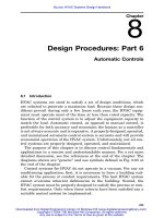
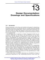
For a blow-through arrangement, the fan work causes an increase
in the mixed-air temperature before the air goes through the cooling
coil, and the process will be as shown in Fig. 11.2. In this case, it will
be necessary to increase the supply air TD to 22ЊF to get a valid coil
leaving condition.
Equipment: Part 3
Downloaded from Digital Engineering Library @ McGraw-Hill (www.digitalengineeringlibrary.com)
Copyright © 2004 The McGraw-Hill Companies. All rights reserved.
Any use is subject to the Terms of Use as given at the website.
Equipment: Part 3 369
Figure 11.2
Psychrometric chart for blow-through air conditioning process.
Humidity control is not always required, but some upper limit will
be inherent in any refrigeration-type cooling process—chilled water,
brine, or direct expansion.
Supply air-handling equipment may be classified in several different
ways:
1. Type or arrangement. The five basic arrangements are single-
zone, multi-zone, double-duct, variable air volume (VAV), and in-
duction.
2. Package versus built-up. Package equipment is factory-assembled,
and when it is installed, it requires only connections for utilities
and ductwork. The term built-up implies that most of or all the
components are field-assembled and installed.
3. Self-contained. A self-contained system includes internal thermal
energy generation.
4. Central station and terminal units. Central station equipment is
remote from and delivers air through ductwork to the conditioned
space. Terminal units are installed in or adjacent to the conditioned
space. Terminal units are used in conjunction with central station
equipment.
Equipment: Part 3
Downloaded from Digital Engineering Library @ McGraw-Hill (www.digitalengineeringlibrary.com)
Copyright © 2004 The McGraw-Hill Companies. All rights reserved.
Any use is subject to the Terms of Use as given at the website.
370 Chapter Eleven
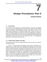
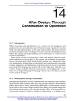
Figure 11.3
Single-zone AHU.
Exhaust systems may serve a single space or multiple spaces, and
may include heat recovery, special filtration, and other special equip-
ment.
11.2 AHU System Arrangements
Air conditioning practice includes only five basic AHU arrangements,
although there are many variations on these basic concepts. Single-
zone and VAV systems have similar, even identical, physical arrange-
ments but use different control strategies. Multizone and double-duct
systems are similar in arrangement and concept but are different
enough to be considered separately. Induction systems are unique.
11.2.1 Single-zone AHU
A single-zone AHU is intended to serve only one room, or a group of
rooms which are contiguous and which have similar load and exposure
characteristics. The maximum area served by a single-zone AHU
should not exceed 10,000 ft
2
.
The typical single-zone AHU arrangement is shown in Fig. 11.3.
This is a draw-through system, with the heating coil in the preheat
position to protect the cooling coil from freezing air. The system is
controlled as explained in Sec. 8.5.2. It is important to sequence the
operation of the control valves to avoid simultaneous heating and cool-
ing.
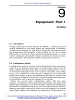
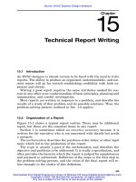
When one or more of the rooms served by a single-zone AHU has a
load characteristic different from the other rooms, zone reheat must
be provided by means of coils in the zone branch ducts (Fig. 11.4), by
radiation, or by fan-coil units. Because reheat is potentially energy-
wasteful, it may be preferable to use a different type of AHU, as de-
scribed below.
Equipment: Part 3
Downloaded from Digital Engineering Library @ McGraw-Hill (www.digitalengineeringlibrary.com)
Copyright © 2004 The McGraw-Hill Companies. All rights reserved.
Any use is subject to the Terms of Use as given at the website.
Equipment: Part 3 371
Figure 11.4
Zone reheat coil.
A single-zone unit may be used to control humidity in the room. The
unit is arranged as shown in Fig. 11.5. The cooling coil precedes the
heating coil, which is therefore in the reheat position. Humidity con-
trol always requires additional energy—as reheat or in other ways.
The cooling coil valve is controlled by either the space temperature or
the space humidity, whichever creates the greater demand. If humid-
ity controls, the temperature will tend to fall and the space thermostat
will control the heating coil valve to provide reheat. The humidifier is
used when required.
11.2.2 Multizone AHU
The typical multizone (MZ) AHU arrangement is shown in Fig. 11.6.
Side-by-side hot and cold airstreams are provided. Each zone is pro-
vided with dampers to mix hot and cold air to satisfy the requirements
of the zone. In this way, one zone may be heated while simultaneously
another is cooled. The mixing dampers are located at the unit, with a
separate duct run to each zone. Thus, economics and practicality limit
the size of the typical MZ unit. The great majority of such units are
the package type.
From an environmental control standpoint, the conventional MZ
unit is less than ideal. Because the control is achieved by reheat, it is
an energy waster. The three-duct MZ unit (Fig. 11.7) retains the con-
trol benefits while eliminating the energy waste, by adding a bypass
duct (plenum). The sequence of control is described in Sec. 8.5.3.
Equipment: Part 3
Downloaded from Digital Engineering Library @ McGraw-Hill (www.digitalengineeringlibrary.com)
Copyright © 2004 The McGraw-Hill Companies. All rights reserved.
Any use is subject to the Terms of Use as given at the website.
372
Figure 11.5
Single-zone AHU with humidity control.
Equipment: Part 3
Downloaded from Digital Engineering Library @ McGraw-Hill (www.digitalengineeringlibrary.com)
Copyright © 2004 The McGraw-Hill Companies. All rights reserved.
Any use is subject to the Terms of Use as given at the website.
373
Figure 11.6
Traditional arrangement for multizone AHU.
Equipment: Part 3
Downloaded from Digital Engineering Library @ McGraw-Hill (www.digitalengineeringlibrary.com)
Copyright © 2004 The McGraw-Hill Companies. All rights reserved.
Any use is subject to the Terms of Use as given at the website.
374
Figure 11.7
Three-duct arrangement for multizone AHU.
Equipment: Part 3
Downloaded from Digital Engineering Library @ McGraw-Hill (www.digitalengineeringlibrary.com)
Copyright © 2004 The McGraw-Hill Companies. All rights reserved.
Any use is subject to the Terms of Use as given at the website.
Equipment: Part 3 375
11.2.3 Double-duct (dual-duct) AHU
The double-duct (DD) AHU uses the same principle of operation as
the MZ unit. However, the hot and cold ducts are extended through
the building, with a mixing box provided for each zone. Thus, the dou-
ble-duct AHU can be as large or as small as desired. The conventional
system (Fig. 11.8) has the same advantages and disadvantages as the
multizone AHU. Many of the older systems installed in the 1950s and
1960s were designed with high-velocity/high-pressure duct systems to
minimize the space occupied by the ducts. Electric energy was rela-
tively inexpensive at that time, so the additional fan work was of little
concern. Five to six inches of total pressure across the fan was com-
mon, and 9 to 10 inches was not unusual. At today’s energy prices,
such a system may cost more for fan energy than for thermal energy
on an annual basis.
Many of these older systems are being retrofitted to variable air
volume by changing the heating coil to cooling, removing the mixing
boxes, and using both heating and cooling ducts, in parallel, with new
VAV boxes. In this way, the duct air velocity is reduced by about 50
percent with a significant saving in fan energy. Some reheat must be
added for exterior zones.
The ideal dual-duct system is, perhaps, the two-fan system shown
in Fig. 11.9 and described in detail in Sec. 8.5.4.
11.2.4 Variable-volume AHU
Unlike the AHU systems previously discussed, a VAV system supplies
air at constant, or nearly constant, temperature and humidity. Capac-
ity is controlled to match cooling load by varying the volume of air
supplied to a zone. A VAV box is provided at each zone. The box in-
cludes a motorized damper (controlled by the zone thermostat) and
usually some means of compensating for changes in static pressure in
the supply duct. Such changes can affect the accuracy of control. The
compensating device may be mechanical, e.g., a spring-loaded damper,
or it may be a flow-sensing controller which is reset by the zone ther-
mostat. The latter is given the anomalous description constant vari-
able-volume controller. Pressure independent is another term used to
describe this type of VAV box control. While the zone supply volume
could theoretically go to zero, it is usual to provide a low limit of 35
to 40 percent of design airflow to maintain a minimum air distribution
and ventilation rate. Supplemental heating—reheat coils, radiation,
fan-coil units—is required in zones with exterior exposure.
VAV systems were developed in response to the 1973 ‘‘energy crisis.’’
The concept is based on the fan law which states that the fan horse-
power (fan work energy) varies as the cube of the airflow, denoted by
Equipment: Part 3
Downloaded from Digital Engineering Library @ McGraw-Hill (www.digitalengineeringlibrary.com)
Copyright © 2004 The McGraw-Hill Companies. All rights reserved.
Any use is subject to the Terms of Use as given at the website.
376
Figure 11.8
Traditional arrangement for double-duct AHU.
Equipment: Part 3
Downloaded from Digital Engineering Library @ McGraw-Hill (www.digitalengineeringlibrary.com)
Copyright © 2004 The McGraw-Hill Companies. All rights reserved.
Any use is subject to the Terms of Use as given at the website.
377
Figure 11.9
Two-fan double-duct AHU.
Equipment: Part 3
Downloaded from Digital Engineering Library @ McGraw-Hill (www.digitalengineeringlibrary.com)
Copyright © 2004 The McGraw-Hill Companies. All rights reserved.
Any use is subject to the Terms of Use as given at the website.
378 Chapter Eleven
Figure 11.10
Volume damper for duct pressure control.
CFM. A reduction to 50 percent of the design CFM could result in a
theoretical reduction to one-eighth of the design fan work. In practice,
the method used to reduce the fan CFM determines the energy sav-
ings, and the full theoretical savings is never realized, due to mini-
mum system pressure requirements, to mechanical friction, and to air
turbulence. Three methods are used to reduce fan CFM.
1. Damper in duct, either upstream or downstream of the fan (Fig.
11.10). This forces the fan to ‘‘ride up the curve’’ (Fig. 11.11), i.e.,
to increase the fan pressure at the lower CFM. Little or no energy
is saved.
2. Inlet vane damper. The inlet vane damper alters the fan perform-
ance, and a portion of the theoretical saving is realized. For actual
savings, consult the fan manufacturer. See the discussion in Sec.
5.2.5.
3. Fan speed control. Fan speed control allows most of the theoretical
savings to be realized—except for mechanical and motor efficiency
losses. Mechanical belt and variable-pitch pulley systems change
the fan speed while the motor speed remains constant. These sys-
tems are satisfactory for small motors and are usually limited to
residential and small commercial applications. Variable-speed
clutch drives—hydraulic and magnetic types—allow constant mo-
tor speed. Some of these systems are satisfactory for large motors,
but they have been largely superseded by variable-speed motor
drives. Variable-speed motor drives of the variable-frequency type
are the preferred method today (see the discussion in Sec. 8.3.3.3).
Equipment: Part 3
Downloaded from Digital Engineering Library @ McGraw-Hill (www.digitalengineeringlibrary.com)
Copyright © 2004 The McGraw-Hill Companies. All rights reserved.
Any use is subject to the Terms of Use as given at the website.