Cảm biến trong sản xuất P17
Bạn đang xem bản rút gọn của tài liệu. Xem và tải ngay bản đầy đủ của tài liệu tại đây (301.66 KB, 11 trang )
5.1
Ultra-precision Machining: Nanometric Displacement Sensors
E. Brinksmeier, Universität Bremen, Bremen, Germany
Sensors used for ultra-precision machines include position and velocity sensors,
which are mostly part of a control loop, and for some special applications accelera-
tion sensors for active vibration control, and thermal sensors for thermal error
compensation [1].
An essential component of each positional feedback loop in a machine tool is
the displacement measurement system for detecting the actual position of moving
machine parts. It is the performance of such measurement systems that limits
the accuracy of machine tools and hence directly affects the quality of the ma-
chined part. In ultra-precision machining, accuracies of interest are of one part in
10
6
or even 10
7
with a measurement range of up to 1 m. Adequate resolutions are
in the range of nanometers [2]. Such demands can only be fulfilled by laser inter-
ferometers, optical scales, and linear voltage differential transducers, which will
be covered in detail. Although capacitive and piezoresistive sensors are able to of-
fer resolutions in the sub-nanometer range, their measurement range is rather
small, which limits their application to measuring macroscopic workpieces [1].
5.1.1
Optical Scales
Optical scales are based on a repetitive pattern of reflective or transmissive
material. On scanning along the scale, a periodic signal is obtained which is a
direct measure for the traveled path. Conventional optical encoders, also called
photoelectric encoders, are based on counting Moiré lines by means of a light
source and a photodiode. Beside optical scales, the patterns might also be made
of magnetic or conductive material. The principle is then based on magnetic,
capacitive, or inductive measurement [2, 3].
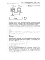
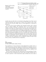
The optical set-up for an incremental photoelectric device is shown in Fig-
ure 5.1-1. The scale is divided into alternating optically opaque and transparent
sectors. A mask with the same grating period and a phase shift of 908 with re-
343
5
Developments in Manufacturing and Their Influence on Sensors
Sensors in Manufacturing. Edited by H.K. Tönshoff, I. Inasaki
Copyright © 2001 Wiley-VCH Verlag GmbH
ISBNs: 3-527-29558-5 (Hardcover); 3-527-60002-7 (Electronic)
spect to each other is located between the light source and the scale. The images
of the sectors are projected on to the scale by the collimated light from the light
source. As the scale moves, four photodiodes on the other side of the mask re-
ceive light pulses which pass through the transparent slits of the mask and the
scale. Thus, four square sine signals with a relative phase shift of 908 are gener-
ated. The determination of the displacement x from these signals is depicted in
Figure 5.1-2.
Two of the signals with a phase shift of 1808 are subtracted so that two signals,
S
1
and S
2
, which are symmetrical with respect to the x-axis and have a phase shift
of 908, are generated. These signals are triggered and finally a resolution of ¼ of
the grating period g is achieved. By counting the intersections of both functions
with the x-axis, the traveled path can be determined. A further increase in resolu-
tion can be achieved by means of electronic interpolation. In Figure 5.1-2, the in-
tensities of S
1
and S
2
can be expressed as sine and cosine functions depending on
the traveled path:
S
1
$ sin
2px
g
S
2
$ cos
2px
g
:
Dividing S
1
by S
2
, the path x can be derived by extracting the arctangents from
the coefficient:
5 Developments in Manufacturing and Their Influence on Sensors344
Fig. 5.1-1
Photoelectric scale. Source: Ernst [3]
x
g
2p
arctan
S
1
S
2
:
One serious drawback of incremental encoders is that the information about the
position is lost when the system is switched off. This disadvantage can be avoided
with absolute encoders. Today, most absolute linear encoders are based on the
photoelectric principle combined with a coded scale. The linear encoder gives an
output which is a binary number that is directly proportional to the distance of
the encoder from a fixed point. The simplest code is the binary code consisting of
alternating opaque and transparent blocks, as shown in Figure 5.1-3. The number
of strips determines the number of binary digits and the total number of incre-
ments that can be detected. For example, using 16 bits (and thus strips), the num-
ber of resolvable positions is 65 536. The position is measured with a linear array
of photodiodes mounted above each strip. One problem that arises with binary
coded scales of the above-mentioned type is that reading errors of the photodiodes
result in large errors in position. Therefore, another code is used where only a
change in one digit occurs when moving from one position to the next. This code
is termed the gray code. Transformation from the gray code to the binary code
and vice versa can be done using simple logical operations. However, a general
drawback of both the gray code and the binary code is the huge number of strips
required for high resolutions and large measurement ranges which requires a lot
of space within a machine tool. Absolute coding with only a few strips can be
5.1 Ultra-precision Machining: Nanometric Displacement Sensors 345
Fig. 5.1-2
Interpolation techniques for optical scales. Source: Ernst [3]
achieved with the random code. Here, the strip is coded in a random fashion over
the entire length so that a sector of a certain critical length never repeats. If a sen-
sor array with equal critical length scans the coded strip, the information obtained
from the array is unique and can be compared with the code stored in the mem-
ory. Thus, the absolute position is obtained. Theoretically, one strip is sufficient
for absolute encoding, available random coded encoders have three strips for in-
creased resolution [3].
Conventional optical photometric encoders are limited in resolution owing to
diffraction effects. On the other hand, so-called interferential scales are based on
diffraction [5]. The optical set-up of the interferential encoders (by courtesy of Hei-
denhain Co.) consist of a movable reflective scale (grating), a transmissive grating
with the same grating period as the scale, a light-emitting diode (LED) as light
source, a condenser and three photodiodes for scanning the signals. The scale
grating consists of 4 lm wide, rectangular plateaus of gold with a height of
0.2 lm, which are located at equal intervals of 8 lm on a gold-plated substrate.
5 Developments in Manufacturing and Their Influence on Sensors346
Fig. 5.1-3
Binary and gray code. Source: Sinclair [4]
Fig. 5.1-4
Principle of interfero-
metric scale. Source: Spies [5]
Figure 5.1-4 shows the operating scheme of the Heidenhain linear encoder. On
passing through the transmissive grating, a first-order diffraction pattern is
created, with three partial waves of nearly the same intensity. The grating is de-
signed in such a way that the zero-order wave is subject to a phase shift w, with
respect to the first-order diffraction waves [5].
At the reflective scale grating the light is diffracted so that the first-order diffrac-
tion has the highest intensity while the zero-order diffraction is negligible. Be-
sides being diffracted, the three waves are also subject to another phase shift X at
the scale grating. Passing through the transmissive phase grating again, three
new interfering waves with different phases are generated. These waves are colli-
mated by the condenser at three different spots to be analyzed by the photo-
diodes. The phase shift of the three new waves is given as by
D
1
2X 2w
D
2
2X
D
3
2X À 2w :
However, the phase shift X is not a constant like w but depends on the move-
ment of the scale grating. When the scale is moving by a distance x, the phase
shift is
X
2px
g
where g denotes the grating period. Hence the phase shifts D
1
, D
2
, and D
3
can be
expressed as a variable depending on the constant w and the displacement x. The
three photodiodes in the focal plane of the condenser generate three periodic sig-
nals with twice the period of the grating and having a phase shift of 2w each:
D
1
2
2px
g
2w
D
2
2
2px
g
D
3
2
2px
g
À2w :
Common to all different interference scales is that the interference phenomenon
is used to generate sinusoidal signals which are a function of linear displacement.
These signals can further be processed electronically to increase the resolution.
Generally, the displacement x can be expressed as [2, 3, 5]:
x
i
kf
g
where i is the number of counts, g the grating period, f the optical multiplication
factor, and k the electronic interpolation factor. With electronic interpolation, an
5.1 Ultra-precision Machining: Nanometric Displacement Sensors 347