Cảm biến trong sản xuất P18
Bạn đang xem bản rút gọn của tài liệu. Xem và tải ngay bản đầy đủ của tài liệu tại đây (417.28 KB, 4 trang )
5.2
High-speed Machining
H. K. Tönshoff, Universität Hannover, Hannover, Germany
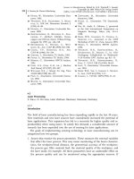
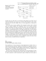
Several developments made high-speed cutting (HSC) possible. HSC became an
important trend in machining (Figure 5.2-1). The development of tool materials
was a prerequisite to higher wear resistance under high temperatures. Up to the
1960s, the dualism of hardness and wear resistance on the one hand and tough-
ness on the other were dominant limiting factors in tool materials. The functional
separation of the ability to carry static and dynamic loads and of tribological func-
tions was established by introducing coatings. The development of tougher ceram-
ic materials for cutting purposes with their high-temperature strength was an-
other way to withstand high cutting velocities. Finally, the progress in synthesiz-
ing super-hard materials such as diamond, diamond coatings, and cubic boron ni-
tride gave strong impulses from the process side for higher cutting speeds.
Important preconditions had to be established on the machine tool side. High
cutting speeds means high spindle rotational frequencies. The bearings of the
main spindle had to be enabled:
· to withstand the centrifugal forces increasing with the square of the rotational
frequency;
· to generate only small power losses and thus keep heat generation limited;
· to be provided with sufficient dynamic stiffness in the domain of exciting fre-
quencies; and
· to avoid wear even under high thermal and dynamic loading.
Progress has been made by introducing hybrid ball bearings where the bearing
balls are made of ceramic with less mass and favorable tribological properties, full
ceramic bearings, and active magnetic bearings. This means that the characteristic
bearing number d
m
n (d
m
= average bearing diameter, n = spindle frequency) could
increase from 0.8 ´ 10
6
to 1.8 ´ 10
6
and 4 ´ 10
6
mm/min.
354
Fig. 5.2-1
Preconditions and advantages of HSC
Sensors in Manufacturing. Edited by H.K. Tönshoff, I. Inasaki
Copyright © 2001 Wiley-VCH Verlag GmbH
ISBNs: 3-527-29558-5 (Hardcover); 3-527-60002-7 (Electronic)
In the same way the feed drives of machine tools have also developed consider-
ably. Important innovations are alternating current (AC) rotational servodrives
with new magnetic materials, fast frequency converters, and ball screws whose
maximum speed limit used to be 30–50 m/min and now reach 100 m/min. This
development was probably induced by another competing technology, the direct
linear motor, which permits high accelerations and high speeds. For this reason it
is superior to rotational drives provided that the driven mass is not too large.
Finally, developments within the control sector have to be mentioned when
speaking about HSC. Powerful closed-loop controls with feedforward and cross-
coupling abilities were introduced and made the necessary data rates possible
with an increase in speeds by factors of 3–5 or even more.
The advantages of HSC which brought the wider dissemination of this technol-
ogy especially in the aircraft industry, in tool and molds manufacturing, and in
the production of gears and drives are manifold. The material removal rates could
be increased with the cutting speed because in milling – the main application
field of HSC – the feed velocity could be increased proportionally if no further re-
strictions exist. The surface roughness may be improved by using parts of the
speed improvement for shorter feeds per cutting edge. This is especially valuable
in those domains of application in which free-form surfaces are generated by ball-
or torus-shaped end mills. It was also stated that the physical state of a surface
may be improved by HSC because the generated surface and the subsurface
layers are less affected by heat. This is mainly a consequence of the time depen-
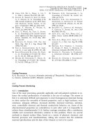
dence of heat conduction. It is also due to lower energy consumption which some
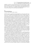
materials show under high cutting speeds (Figure 5.2-2). The specific energy and
hence the cutting force decrease with increase in cutting speed. In addition, the
forces can be lowered by decreasing the feed per cutting edge. This may be of de-
cisive importance when filigree parts are machined as in the aircraft industry
where integral structure parts are very susceptible to elastic deformations during
milling and may consequently be incorrectly machined.
5.2 High-speed Machining 355
Fig. 5.2-2
Cutting force at varying cutting speeds
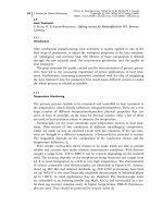
Although interesting advantages in connection with HSC can be listed, there
are problems, some of which can be avoided or minimized by the use of sensors
(Figure 5.2-3). The process cannot be monitored by the operator on-line, and
therefore precautions against collisions have to be taken. This is done today by
software running off-line or in the background of a numerically controlled (NC)
program. For HSC, on-line calculations are normally too time consuming (see
Section 2.4). Therefore, sensors are required which can follow all movements in
the working area of machining. There have been some developments and investi-
gations in research laboratories, eg, using ultrasonic curtains or infrared radia-
tion, but up to now a solution which is robust enough for practical use, especially
in the environment of chips and coolant, has not been found.
Depending on the material, HSC opens up only a narrow process window in
which the machining conditions have to be set. This process window is depen-
dent on some influences which are difficult to identify. These are especially the
properties of the material to be machined. There may be serious disturbances if
the process is implemented outside the window. Therefore, power, torque, and/or
force monitoring are important. This is especially true because of the high invest-
ment value that HSC machines normally have. Even if such devices cannot pre-
vent collisions, they may limit the consequences and damage which follow such
an incident.
The high rotating frequencies in HSC make the run out and the imbalance of
the spindle critical. The centrifugal forces grow with the square of the r.p.m. and
so does the imbalance. The interfaces of the tool clamping system, that is, the
connection between spindle and tool holder and between tool holder and tool,
have to be specifically designed. The hollow taper shaft (HSK) was introduced
some years ago with good success. Sensorial supervision of its correct fit in the
spindle is provided in some machining centers. Monitoring of the run out and
imbalance by an accelerometer is another safety feature for HSC.
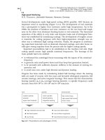
As is known from the Taylor equation, the cutting speed has a dominant influ-
ence on the tool life. HSC means, therefore, that the tools have to be changed fre-
5 Developments in Manufacturing and Their Influence on Sensors356
Fig. 5.2-3
Sensor applications of HSC processes
imbalance sensing
quently and more often than in conventional cutting (Figure 5.2-4). Wear may be
critical and therefore wear sensors are of interest. They should be able to deter-
mine the end of tool life reliably. There are several approaches, as discussed in
Section 4.3.
One of the main accuracy problems with automated machine tools is derived
from the thermal stability. The temperature field in the machine structure
changes according to the effect of several heat sources. The most important heat
sources are very often the spindle bearings. The monitoring of the bearing tem-
perature is recommended because of the high investment that an HSC machine
represents and the critical power losses with high spindle frequencies. The heat-
ing of fast-running main spindles can lead to an unstable state: heating increases
the pre-stressing of the spindle-bearing system, which increases power losses and
heating, etc. Monitoring is therefore advisable. This can be done fairly easily and
reliably by thermocouple sensors. Similar measuring devices might be advisable
to monitor feed drive components such as spindle-nut systems and direct linear
drives to ensure a tolerable increase in temperature.
5.3
Micro-machining
M. Weck, RWTH Aachen, Aachen, Germany
The manufacture of micro-components using high-precision machine tools, so-
called ultra-precision machines, imposes new demands on integrated sensor sys-
tems. In micro-machining, extremely filigree turning, planing, or milling tools are
frequently used. In addition, the machining forces are very low, typically in the
range below 1 N when natural diamond tools are used.
Very few sensor systems meet the requirements for micro-machining. To deter-
mine process forces, piezoelectric force sensors with very high resolutions have to
be used to generate a useful measurement signal. Attempts have been made to
ng 357
Fig. 5.2-4
Tool life with high
cutting speeds.
Source: kindly provided by
B. Denkena, University of
Hannover