Lecture Computer organization and assembly language - Lecture 05: Memory Access - TRƯỜNG CÁN BỘ QUẢN LÝ GIÁO DỤC THÀNH PHỐ HỒ CHÍ MINH
Bạn đang xem bản rút gọn của tài liệu. Xem và tải ngay bản đầy đủ của tài liệu tại đây (410.46 KB, 10 trang )
<span class='text_page_counter'>(1)</span><div class='page_container' data-page=1>
<b>CSC 221</b>
<b>Computer Organization and </b>
<b>Assembly Language</b>
</div>
<span class='text_page_counter'>(2)</span><div class='page_container' data-page=2>
<b>Lecture 4: Review</b>
•
The programming model of the 8086
through 80286 contain 8- and 16-bit
registers.
•
The programming model of the 80386 and
above contains 8-, 16-, and 32-bit
extended registers as well as two
</div>
<span class='text_page_counter'>(3)</span><div class='page_container' data-page=3>
<b>Lecture 4: Review</b>
•
The 64-bit registers in a Pentium 4 with
64-bit extensions are RAX, RBX, RCX,
RDX, RSP, RBP, RDI, RSI, and R8
through R15.
•
In addition, the microprocessor contains
an instruction pointer (IP/EIP/RIP) and flag
register (FLAGS, EFLAGS, or RFLAGS).
</div>
<span class='text_page_counter'>(4)</span><div class='page_container' data-page=4>
<b>Lecture Outline</b>
•
Memory Access:
– Real Mode memory-addressing techniques.
– Protected Mode memory-addressing techniques.
•
Memory Access:
– 64-bit Flat Memory model.
• Program-invisible registers in the 80286~Core2
</div>
<span class='text_page_counter'>(5)</span><div class='page_container' data-page=5>
• The only mode available on the 8086-8088.
20 bit address bus 1 MB, 16 bit data bus, 16 bit registers
• 80286 and above operate in either the real or
protected mode.
• <b>Real mode operation</b> allows addressing of only
the first 1M byte of memory space—even in
Pentium 4 or Core2 microprocessor.
– the first 1M byte of memory is called the <b>real memory</b>,
</div>
<span class='text_page_counter'>(6)</span><div class='page_container' data-page=6>
<b>Segments and Offsets </b>
• All real mode memory addresses must consist of a
segment address plus an offset address.
– <b>segment address </b>defines the beginning address of any
64K-byte memory segment
– <b>offset address</b> selects any location within the
64K byte memory segment
• Figure in Next Slide: shows how the <b>segment plus </b>
</div>
<span class='text_page_counter'>(7)</span><div class='page_container' data-page=7>
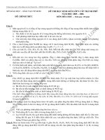
<b>Figure: The real mode memory-addressing scheme, using a segment address </b>
<b>plus an offset. </b>
– this shows a memory
segment beginning at
10000H, ending at
location IFFFFH
• 64K bytes in length
– also shows how an offset
address, called a
<b>displacement</b>, of F000H
selects location 1F000H
in the memory
</div>
<span class='text_page_counter'>(8)</span><div class='page_container' data-page=8>
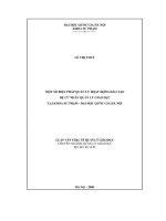
<b>Figure: The real mode memory-addressing scheme, using a segment address </b>
<b>plus an offset. </b>
<b>Segments and Offsets </b>
<b>16-bit each</b>
Appended 4 bits (0H)
Segment Start Address
in Segment Register
0
Then the Effective memory Address (EA) =
</div>
<span class='text_page_counter'>(9)</span><div class='page_container' data-page=9>
<b>Effective Address Calculations</b>
• EA = segment register (SR) x 10H + offset
(a) SR: 1000H
10000 + 0023 = 10023
(b) SR: AAF0H
AAF00 + 0134 = AB034
(c) SR: 1200H
</div>
<span class='text_page_counter'>(10)</span><div class='page_container' data-page=10>
• Once the beginning/starting address is known, the
<b>ending address</b> is found by adding FFFFH.
– because a real mode segment of memory is 64K in
length
• The offset address is always added to the
segment starting address to locate the data.
• Segment and offset address is sometimes written
as 1000:2000.
</div>
<!--links-->