Tài liệu Mastering Revit Architecture 2008_ Part 18 pptx
Bạn đang xem bản rút gọn của tài liệu. Xem và tải ngay bản đầy đủ của tài liệu tại đây (889.27 KB, 19 trang )
Chapter 18
Advanced Detailing Techniques
Chapter 17 covered the transition from design to construction documentation. In this chapter, you
will continue building your skills and learn some additional techniques for more detailed construc-
tion documentation. As your project experience grows, your library and detailing capacity within
Revit will grow with it. This chapter is dedicated to tools and functionality that you can employ
after you become comfortable with creating details in Revit. By building your library and knowl-
edge of detailing workflows, you can cut down the time you spend detailing, leaving more time
for design.
You will acquire the following skills:
◆
Create 3D details
◆
Add detail components to 3D families
◆
Export details for use in other Revit projects
Creating 3D Details
As building designs become more and more complex and the construction industry continues to
specialize its assembly methods, it has become imperative that information be communicated effec-
tively between designer and contractor. A technique for showing construction assemblies that goes
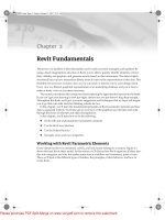
way back in the history of architectural representation is the use of 3D detail drawings (Figure 18.1)
that show a sectional cut through the building in a 3D format (axon or perspective). This type of
drawing has been used to convey detail and constructability information rather than create a mul-
titude of abstract sections and elevations. In recent years, this documentation technique has fallen
into disuse because it has been difficult or time consuming to re-create such axonometric details in
a 2D CAD-based environment.
With Revit’s 3D modeling capabilities, it is easy to create such 3D details. By using the 3D views
and
orienting to other views
, you can quickly generate 3D views that focus on a construction condi-
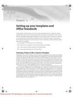
tion. These can be for constructability or to demonstrate critical building concepts. Figure 18.2
shows a detail of a sustainable solution employed on the Foundation project. In this sectional axon,
we are able to demonstrate many of the green building concepts simultaneously while also show-
ing dimensional depths of both sun-shading systems.
Creating this kind of 3D detail in Revit is quick and easy to learn. There are two methods you can use:
◆
Turning on the Section Box tool, and then adjusting the section box to focus on your detail
◆
Orienting a 3D view to an existing view, which in turn enables a section box for the view
44831c18.fm Page 581 Friday, October 12, 2007 9:08 AM
Please purchase PDF Split-Merge on www.verypdf.com to remove this watermark.
582
CHAPTER 18
ADVANCED DETAILING TECHNIQUES
Figure 18.1
Hand-drawn
perspective detail
44831c18.fm Page 582 Friday, October 12, 2007 9:08 AM
Please purchase PDF Split-Merge on www.verypdf.com to remove this watermark.
CREATING 3D DETAILS
583
Figure 18.2
Sectional axon
showing details of
sun-shading solution
Enabling a Section Box in 3D View
Take the following steps to enable the Section Box tool in a 3D view.
1.
Start by creating or opening a 3D axon of the building. If there is not one created, click the
Default 3D View button in the toolbar at the top of the screen. Make sure to name your view
something unique.
2.
Open View Properties and enable the Section Box parameter. A large section box that sur-
rounds the entire model will appear in the view. This is a 3D clipping box that will cut the
model from six directions.
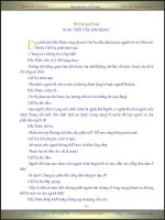
3.
By clicking and dragging the blue arrows, you reduce the size of the box to be more precise
(Figure 18.3). Manipulating a section box can take a bit of trial and error, regardless of your
experience with Revit. Later in this chapter, we’ll discuss some ways to make this quicker
and more accurate.
Figure 18.3
Use the blue arrows to
size the section box
44831c18.fm Page 583 Friday, October 12, 2007 9:08 AM
Please purchase PDF Split-Merge on www.verypdf.com to remove this watermark.
584
CHAPTER 18
ADVANCED DETAILING TECHNIQUES
The Second Technique: Orienting to View
An alternative for creating a 3D detail is to orient the 3D view to an existing view. Do this by first
creating a detail callout in a wall section (Figure 18.4). By selecting the callout and editing its prop-
erties, you can give it a recognizable name, such as Sunshade Detail. Having a recognizable name
will be important because the number of details in a project can become quite large.
Figure 18.4
Creating a callout
detail in section
1.
Open the default (3D) view and choose View
Orient
To Other View, and select our
Sunshade Detail from the list (Figure 18.5).
Figure 18.5
Selecting a view from
View
Orient
To
Other View
2.
Once you click OK, the view will reorient and appear as a section—just like the detail callout.
However, this is a 3D view. By orbiting the view (using either the Dynamically Modify View
button or combining Shift and the middle mouse button), you’ll be able to visualize the
sectional detail in 3D (Figure 18.6).
44831c18.fm Page 584 Friday, October 12, 2007 9:08 AM
Please purchase PDF Split-Merge on www.verypdf.com to remove this watermark.
CREATING 3D DETAILS
585
Figure 18.6
Top: Oriented To
Other View detail
looks like a flat
section; Bottom: the
rotated (orbited) view
reveals a 3D detail
The crop boundaries of the 3D detail correlate to the boundaries of the callout, so there is no need
to alter the section box. The depth of the section box in this view will be defined by the depth of the
view you have used to orient. You can of course edit the section box using the grip controls. To hide
the section box lines but keep it cutting the model, select it and choose Hide element in view from
the context menu.
Adding Annotations to the 3D Detail
To add dimensions to a 3D view, first define the work plane the dimensions will appear on, as they
can not “float” in free space and need a workplane to be drawn on. (See Chapter 6 for more on work
planes.) We are showing our dimensions at Level 3 in the view. Click the Work Plane button on the
toolbar and select Level 3 from the drop-down menu. Using the work plane visibility toggle, you’ll
be able to see what plane the dimensions will be created on, as shown in Figure 18.7. Dimensioning
along this plane will be very similar to dimensioning in any plan view. By selecting parallel ele-
ments, we can apply the necessary dimensions.
You can then begin to add notes. Note that in a 3D view, you can add text and dimensions but
not keynotes or tags. Also, be careful
not to rotate the axon
after you apply your notes. Text is placed
perpendicular to the view you have created, and rotating the view will make the text difficult to read.
44831c18.fm Page 585 Friday, October 12, 2007 9:08 AM
Please purchase PDF Split-Merge on www.verypdf.com to remove this watermark.
586
CHAPTER 18
ADVANCED DETAILING TECHNIQUES
Figure 18.7
Setting and visualizing
the work plane in a
3-D view
By turning on the shadows in the view, you’ll be able to give the view a better sense of depth,
as shown in Figure 18.2 earlier.
Be sure the ground plane is enabled in the Sun And Shadows Settings dialog for the view. A
good choice is either Sun From Top Right or Sun From Top Left. See Chapter 12 for more detail on
presentation techniques.
Embedding Details within Families
In the previous chapter, we investigated how to add levels of detail to a detail component by cre-
ating one detail out of a number of separate components, making it easier to replicate a detail con-
dition across various project views. Again, this idea of “drawing it once” is a core theory in Revit.
Combining these principles, we can extend this information into family creation, allowing you to
turn details on or off within a family depending on a view’s Level Of Detail setting.
When we explored the notion of the view detail earlier, we mentioned the ability to show dif-
ferent levels of detail at Coarse, Medium, and Fine settings. Combining this with detail compo-
nents, we can embed details for typical conditions directly within the families themselves.
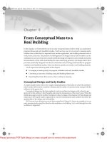
Figure 18.8 shows the same window family in coarse, medium, and fine views. All of the detail has
been added to the family itself, and the detail is activated by switching between View Detail set-
tings. Note that the Fine detail level in this series shows the actual CAD detail from the manufac-
turer’s website and is not modeled in detail in 3D. Modeling this in 3D would be a huge
performance killer. Because we have created this as part of the window family, this highly detailed
information will be displayed each time we cut a window in section, regardless of where the win-
dow is placed in the model.
Building this type of window family is not complicated, but it does require a bit of knowledge
about how a family is created and assembled. For our purposes, we are going to assume that the
window family has been created correctly and we are simply trying to apply more detail to the win-
dow itself so that it displays much more detailed information in fine view. Since we have already
created the sill condition, we will now focus on creating the head detail.
Start by locating the family within the project using the Project Browser. Select it and choose Edit
Family from the context menu. In the Family Editor, open a section view (or if there is no section
view, create a new one). The sectional view of the window family head looks like Figure 18.9.
44831c18.fm Page 586 Friday, October 12, 2007 9:08 AM
Please purchase PDF Split-Merge on www.verypdf.com to remove this watermark.
EMBEDDING DETAILS WITHIN FAMILIES
587
Figure 18.8
The same awning
window shown in
(A) coarse,
(B) medium, and
(C) fine view
Figure 18.9
Sectional view of the
window family head
In Chapter 17, we discussed how to insert default Revit detail components. For the blocking
above the window head, we can load a detail component from the Revit default library.
1.
Navigate to File
Load from Library
Load Family. Then, once the browsing window
opens, you will need to follow the path Detail Components
Div 06-Wood and Plastic
06100-Rough Carpentry
06110-Wood Framing and choose
Nominal Cut Lumber-
Section.rfa
.
2.
Insert this component 1
1
⁄
4
˝ from the exterior face of the wall. This will ensure that it ends up
in the right location relative to the wall it will be inserted into. If this window was going to
be inserted into a variety of wall types, you could make the 1
1
⁄
4
˝ dimension a parametric fam-
ily parameter.
3.
Once this is inserted, lock it to the reference plane that is at the window head. This will
ensure that as window sizes are changed, the blocking moves as well.
AB C
44831c18.fm Page 587 Friday, October 12, 2007 9:08 AM
Please purchase PDF Split-Merge on www.verypdf.com to remove this watermark.