Tài liệu Gate Level Modeling part 1 pptx
Bạn đang xem bản rút gọn của tài liệu. Xem và tải ngay bản đầy đủ của tài liệu tại đây (28.18 KB, 14 trang )
[ Team LiB ]
5.1 Gate Types
A logic circuit can be designed by use of logic gates. Verilog supports basic logic gates
as predefined primitives. These primitives are instantiated like modules except that they
are predefined in Verilog and do not need a module definition. All logic circuits can be
designed by using basic gates. There are two classes of basic gates: and/or gates and
buf/not gates.
5.1.1 And/Or Gates
And/or gates have one scalar output and multiple scalar inputs. The first terminal in the
list of gate terminals is an output and the other terminals are inputs. The output of a gate
is evaluated as soon as one of the inputs changes. The and/or gates available in Verilog
are shown below.
and or xor
nand nor xnor
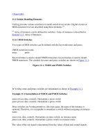
The corresponding logic symbols for these gates are shown in Figure 5-1
. We consider
gates with two inputs. The output terminal is denoted by out. Input terminals are denoted
by i1 and i2.
Figure 5-1. Basic Gates
These gates are instantiated to build logic circuits in Verilog. Examples of gate
instantiations are shown below. In Example 5-1, for all instances, OUT is connected to
the output out, and IN1 and IN2 are connected to the two inputs i1 and i2 of the gate
primitives. Note that the instance name does not need to be specified for primitives. This
lets the designer instantiate hundreds of gates without giving them a name.
More than two inputs can be specified in a gate instantiation. Gates with more than two
inputs are instantiated by simply adding more input ports in the gate instantiation (see
Example 5-1
). Verilog automatically instantiates the appropriate gate.
Example 5-1 Gate Instantiation of And/Or Gates
wire OUT, IN1, IN2;
// basic gate instantiations.
and a1(OUT, IN1, IN2);
nand na1(OUT, IN1, IN2);
or or1(OUT, IN1, IN2);
nor nor1(OUT, IN1, IN2);
xor x1(OUT, IN1, IN2);
xnor nx1(OUT, IN1, IN2);
// More than two inputs; 3 input nand gate
nand na1_3inp(OUT, IN1, IN2, IN3);
// gate instantiation without instance name
and (OUT, IN1, IN2); // legal gate instantiation
The truth tables for these gates define how outputs for the gates are computed from the
inputs. Truth tables are defined assuming two inputs. The truth tables for these gates are
shown in Table 5-1
. Outputs of gates with more than two inputs are computed by
applying the truth table iteratively.
Table 5-1. Truth Tables for And/Or Gates
5.1.2 Buf/Not Gates
Buf/not gates have one scalar input and one or more scalar outputs. The last terminal in
the port list is connected to the input. Other terminals are connected to the outputs. We
will discuss gates that have one input and one output.
Two basic buf/not gate primitives are provided in Verilog.
buf not
The symbols for these logic gates are shown in Figure 5-2
.
Figure 5-2. Buf and Not Gates
These gates are instantiated in Verilog as shown Example 5-2. Notice that these gates can
have multiple outputs but exactly one input, which is the last terminal in the port list.
Example 5-2 Gate Instantiations of Buf/Not Gates
// basic gate instantiations.
buf b1(OUT1, IN);
not n1(OUT1, IN);
// More than two outputs
buf b1_2out(OUT1, OUT2, IN);
// gate instantiation without instance name
not (OUT1, IN); // legal gate instantiation
The truth tables for these gates are very simple. Truth tables for gates with one input and
one output are shown in Table 5-2
.
Table 5-2. Truth Tables for Buf/Not Gates
Bufif/notif
Gates with an additional control signal on buf and not gates are also available.
bufif1 notif1
bufif0 notif0
These gates propagate only if their control signal is asserted. They propagate z if their
control signal is deasserted. Symbols for bufif/notif are shown in Figure 5-3.
Figure 5-3. Gates Bufif and Notif
The truth tables for these gates are shown in Table 5-3
.
Table 5-3. Truth Tables for Bufif/Notif Gates
These gates are used when a signal is to be driven only when the control signal is
asserted. Such a situation is applicable when multiple drivers drive the signal. These
drivers are designed to drive the signal on mutually exclusive control signals. Example 5-