Tài liệu Modeling, Measurement and Control P7 pptx
Bạn đang xem bản rút gọn của tài liệu. Xem và tải ngay bản đầy đủ của tài liệu tại đây (3.85 MB, 15 trang )
7
Forming Processes:
Monitoring and Control
7.1 Introduction: Process and Control Objectives
Process Control Issues • The Process: Material
Diagram • The Machine Control Diagram
7.2 The Plant or Load: Forming Physics
Mechanics of Deformation: Machine Load
Dynamics • Mechanics of Forming: Bending, Stretching,
and Springback
7.3 Machine Control
Sensors
7.4 Machine Control: Force or Displacement?
7.5 Process Resolution Issues: Limits to Process
Control
Process Resolution Enhancement
7.6 Direct Shape Feedback and Control
7.7 Summary
7.1 Introduction: Process and Control Objectives
Forming of metallic materials is the process of choice when complex net shapes with high levels
of productivity are desired. Myriad processes, ranging from job-shop metal bending machines to
very high speed stamping and forging presses are available. In all cases, the processes involve
plastic deformation of the workpiece, and the resulting strong forces required to create plastic
stresses. In this chapter, the problem of controlling such processes is considered from both the
viewpoint of controlling the forming equipment and the deformation process itself. Several unique
aspects of forming processes arise when considering control system design:
1. The process or plant transfer function becomes a static block with variable gain and severe
hysteresis.
2. The plant (the forming process) is inherently variable owing to the sensitivity to the workpiece
material properties.
3. An inherent lack of process degrees of freedom with respect to controlling overall part shape
exists.
Metal forming can be divided into sheet-forming processes and bulk-forming processes (typically
forging). The major difference is that the latter involves a complex three-dimensional flow of the
material, while the former tends to be dominated by plane strain conditions, and the process is not
intended to change material thickness, only the curvatures. In what follows, the sheet-forming
processes are used as model processes, but much of what is developed applies to bulk-forming as
well.
David E. Hardt
Massachusetts Institute
of Technology
8596Ch07Frame Page 105 Tuesday, November 6, 2001 10:17 PM
© 2002 by CRC Press LLC
7.1.1 Process Control Issues
The objective of all sheet-forming processes is to alter the curvature of the material to achieve a
target shape. In so doing, the material also may be intentionally stretched to aid in reducing shape
errors and to induce strain hardening for strength properties. Accordingly, the control objective for
the process is to achieve the desired shape, and (from a manufacturing point of view) to achieve
this shape with rapid setup (flexibility) and minimal part-to-part variation (quality).
Application of control principles can have a great impact on all three: shape fidelity, variation
reduction, and rapid changeover or setup. This control is accomplished either through the use of
machine or process feedback to achieve higher accuracy and repeatability or by facilitating more
mechanically complex machines to enhance process flexibility and control degrees of freedom. In
all cases, the properties of control loops: tracking changing inputs (i.e., new part shapes), rejecting
disturbances, and decreasing sensitivity to process parameter changes (e.g., tool–workpiece friction,
constitutive property changes) are perfect matches to forming processes.
To help see this connection at a phenomenological level, it is useful to develop a set of block
diagrams for these processes.
7.1.2 The Process: Material Diagram
A simple block diagram of the process is shown in Figure 7.1. Here the plant comprises:
• The forming machine or press, which provides the forming energy (force displacement)
• The tooling that takes this
lumped
energy and
distributes
it over the face of the tool–workpiece
interface
• The workpiece material that plastically deforms according to the force or displacement field
In each block a set of constitutive properties determines how the energy or power variable pairs of
each element relate to each other. For the machine blocks these properties would typically be the
stiffness, mass, and damping of the machine as well as the overall geometry. For the workpiece, the
set includes the large strain properties of the material and its initial geometry, which will affect how
the distributed forces and displacements, and moments and curvatures are related. As will be seen,
these material constitutive properties are the largest components of process variability in forming.
7.1.3 The Machine Control Diagram
In practice, the most common type of control used with forming processes is simple feedback of
the machine outputs (herein referred to as
machine contro
l). As with any mechanical process, these
outputs will be displacement or force, and control will involve application of servo-control tech-
nology to the actuators of the machine, whether eletrohydraulic or electromechanical. As shown
schematically in Figure 7.2, closing this loop affords good regulation of these quantities, and will reject
disturbances that enter the machine loop. These could include variations in the net force–displacement
curve of the load (the workpiece) and variations in the machine properties such as friction and
FIGURE 7.1
Basic block diagram for forming.
Forming
Press
Tooling
(shape)
Workpiece
Material
Press
Controls
Part Shape
Force,
Displacement
Machine
Force-
Displacement
Distribution
8596Ch07Frame Page 106 Tuesday, November 6, 2001 10:17 PM
© 2002 by CRC Press LLC
actuator nonlinearities and drift. It also can allow for a rapid change of set-points as production
demands change. However, it cannot change the force–displacement distribution, and it leaves the
part shape (which is the process output) outside the control loop.
Further stages of control can be attempted by actual measurement of forces and displacements
at the tool (material control) and direct measurement of the resulting part shape (shape control).
However, as shown in Figure 7.3, the only variables that can be manipulated are the press set-
points, which are restricted to the limited number of actuator degrees of freedom. This, in turn,
limits the process resolution, which is discussed below as the ultimate limit on process control
effectiveness.
Many mechanical systems issues are involved in forming press control, but it is equally evident
that even with precise control of force and displacement of the press, the resulting shape will still
be a strong function of the tooling and the material itself.
To appreciate the latter aspect of forming processes it is necessary to consider the physics of
forming as viewed in a control system’s context.
7.2 The Plant or Load: Forming Physics
7.2.1 Mechanics of Deformation: Machine Load Dynamics
To consider the control of forming processes it is important to have at least a general understanding
of the mechanics of the load as seen by a forming machine. Here a simple input–output description
of forming is developed that can be shown to cover the basic phenomena of any forming process.
While a detailed model of the deformation process is well beyond the scope of this chapter, the
basic phenomena of forming can be summarized by the classical unidirectional tensile stress–strain
or force–displacement diagram. If we consider the simplest forming operation, that of stretching
FIGURE 7.2
Closed-loop machine control for regulating force or displacement.
FIGURE 7.3
Material feedback and shape feedback control loops.
Forming
Press
Tooling
(shape)
Workpiece
Material
Press
Set-Points
Part Shape
Force,
Displacement
Distribution
Force,
Displacement
-
Closed-Loop
Forming Press
Tooling
(shape)
Workpiece
Material
Part Shape
-
Material
Controller
Shape
Controller
-
Target
Material States
Target
Part Shape
Press
Set-Points
8596Ch07Frame Page 107 Tuesday, November 6, 2001 10:17 PM
© 2002 by CRC Press LLC
a bar of metal from an initial shape to a longer one, the force–displacement relationship of the
workpiece is given by the constitutive stress–strain curve of the material. As shown in Figure 7.4
the curve includes not only the loading portion of the process, but also the unloading.
When looked at from a control system’s perspective, the material appears to be a static block
with nonlinear behavior. This arises from a power law-like plastic region, a hysteresis-like behavior
arising from the elastic unloading behavior, and a history-dependent reference point owing to the
permanent plastic deformation after loading beyond yield.
Because of the low mass of the material relative to the machine and tooling, the dynamics of
the material block are usually ignored. However, the deformation process involves very low damp-
ing, and unless there is considerable sliding friction between the workpiece and tool, the contribution
to overall system damping is minimal.
The variable slope in Figure 7.4 illustrates that if the sheet deformation process is within a control
loop, the level of strain and its history can cause the gain of this element to vary widely, because
the slope of the elastic region of the curve is typically more than an order of magnitude greater
than the equivalent slope of the post-yield curve (the plastic modulus). Consider the impact of this
on a closed-loop force controller for a simple tensile deformation. As shown in Figure 7.5, the
actuator is providing a displacement output, and the tensile force generated in the material is
measured and fed back to the controller. Figure 7.4 is the gain model for the workpiece block, and
it indicates that the overall loop gain will be highly variable over the entire range of deformation,
and will depend as well upon whether the displacement is increasing or decreasing.
7.2.2 Mechanics of Forming: Bending, Stretching, and Springback
Because all forming involves curvature change, some type of bending is always present. One of
the most common and simplest forming processes is brakeforming, which is essentially three-point
bending (see Figure 7.6). At any given cross-section along the arc length of the part, stress and
strain distributions can be approximated by those of pure bending.
FIGURE 7.4
Cyclic loading stress–strain curve showing hysteresis and load-dependent offset.
FIGURE 7.5
Simple tensile force control loop.
Strain ε
Loading
Cycle 1
Loading
Cycle 2
Stress
σ
Controller
Actuator
Press
Set-Points
Force
-
Workpiece
Displacement
8596Ch07Frame Page 108 Tuesday, November 6, 2001 10:17 PM
© 2002 by CRC Press LLC
With the resulting bi-directional stress distribution about the neutral axis, release of the forming
loads leads to elastic unbending of the material. This curvature “springback” is the key source of
error in forming processes, because it causes a difference between the curvature of the part when
loaded to a known displacement and the final unloaded curvature.
To help reduce this springback and to achieve beneficial strain-hardening of the workpiece, the
ends of the material are either constrained not to move or allowed to slip under a frictional force
to provide an additive tensile force in the plane of the part. This process is shown in Figure 7.7
where it can be seen that the resulting stress distribution is now more uniform. As the tensile strain
increases, the stress distribution becomes all positive and nearly constant. (For an idealized material
that does not strain harden it will be constant.) As a result, the elastic unbending or springback of
the part from the loaded curvature is greatly reduced. Consequently, for precision forming opera-
tions, or for operations where very small curvatures are involved (as with the stretch forming process
used in aerospace) an intentional tensile force is added. Also, for three-dimensional forming
problems, this tensile “bias” is also necessary to prevent in-plane buckling.
From the above it is obvious that for sheet forming, springback is the main source of errors, and
variation in the springback will be the main source of process uncertainty. If we consider the simple
bending example of Figure 7.6, the bending constitutive relationship can be written in terms of the
moment–curvature relationship for the sheet. In the elastic region this is given by the simple
relationship:
(7.1)
where
M
= pure bending moment
K
= resulting sheet curvature
E
= modulus of elasticity
I
= area moment of inertia for the sheet,
and for a rectangular cross-section,
FIGURE 7.6
Simple brakeforming. Approximated as three-point bending with resulting stress and strain distri-
butions.
M
M
ε
σ
M
EI
K=
1
8596Ch07Frame Page 109 Tuesday, November 6, 2001 10:17 PM
© 2002 by CRC Press LLC
(7.2)
where
b
= width of the sheet
h
= thickness of the sheet
As the beam curvature
K
increases, the bending moment will increase, and eventually the beam
will begin to yield. When yielding occurs, the bending moment required for incrementally higher
curvatures will decrease, and a moment–curvature relationship such as shown in Figure 7.8 will
emerge. Just as with the tension example of Figure 7.4, the beam, when loaded to a maximum
moment
M
L
, will elastically unload along a line of slope
EI.
The curvature springback
∆
K
will, as
shown in the figure, be determined by the magnitude of this moment and the slope.
Consider now a very simple process where a sheet is formed between a matched set of cylindrical
tools (see Figure 7.9). We are interested in the final curvature (
K
U
) of the part after the sheet is
removed from the tools. The matched tools impose a fixed loaded curvature
K
L
on the sheet, which
will load the sheet as shown in the figure. The amount of springback
∆
K = K
L
–K
U
will depend on
the maximum moment
M
max
and the slope
EI
according to
(7.3)
FIGURE 7.7
Simple two-dimensional draw forming with a blankholder and stretch forming. Notice the effect of
adding stretch: the resulting stress distribution can become nearly uniform for a mildly strain-hardening material.
resulting stress σ
ε
bending
ε
bending
+
ε
stretch
σ
bending
Ibh=
1
12
3
∆K
M
EI
Y
=
8596Ch07Frame Page 110 Tuesday, November 6, 2001 10:17 PM
© 2002 by CRC Press LLC
Because the tooling imposes a fixed (input) curvature, the maximum moment (output) is determined
by the constitutive relationship of the material, most importantly the yield stress and the thickness. The
modulus
E
is most nearly constant, but the moment of inertia
I
varies with thickness to the 3rd power.
Not surprisingly, in practice it is found the most sensitive parameters with respect to springback are
the thickness, the yield stress, and the post-yield (strain-hardening) properties of the sheet.
7.2.2.1 Material Variations
The most common variations in sheet material are the thickness, yield stress, and plastic flow
properties. The thickness can vary owing to rolling mill variations, and while some stock (such as
aluminum beverage can stock) can be rolled to very low variations (~0.0002 in.), larger material
can vary considerably. In some thicker material, and up into plates of thickness > 0.5 in., material
specifications often call for only maintaining a minimum thickness for minimum service strength,
but have a very broad tolerance on maximum thickness.
Perhaps more insidious from a process control perspective is variation of the constitutive prop-
erties of the sheet. If we imagine a linearly strain-hardening material, there are (at least) three
parameters of concern: the elastic modulus
E,
the yield stress
σ
Y
, and the equivalent plastic modulus
E
P
. Because the modulus
E
depends primarily on the crystalline structure of the material, it is nearly
constant for a given material independent of the particular alloy or working history. However, both
σ
Y
and
E
P
are very sensitive to the chemistry, heat-treating, and cold working history of the piece.
Variations in
σ
Y
of up to 20% from supplier to supplier for a given alloy have been reported,
although these quantities vary less within a given mill run or heat of material.
7.2.2.2 Machine Variation
Machine variations in forming are typical of most machine tools except that the loads and corre-
sponding structural distortions are greater than most other processes. Forming loads of 10
3
or even
FIGURE 7.8
Generic moment curvature diagram showing curvature springback
∆
K after unloading from the
loaded curvature K
L
.
FIGURE 7.9
Simple matched tool forming over a cylinder. No edge constraint is used so the sheet sees only a
bending moment if no interface friction is assumed.
Moment
M
Curvature K
∆K
K
L
K
U
EI
M
max
8596Ch07Frame Page 111 Tuesday, November 6, 2001 10:17 PM
© 2002 by CRC Press LLC
10
4
tons are not unusual with sheet and can be far greater for bulk forming. The elastic frames of
the machine will deform with load, changing the relationship of the actuator displacements to the
actual displacement of the tool–sheet interface.
Consider the situation shown in Figure 7.10. This shows the “C” frame typical of a pressbrake
or stretch-forming machine. Clearly, the frame opening will stretch under load, and if the displace-
ment sensor is collocated with the actuators, a load-dependent bias will always occur. It is also
possible for the frame to bend as shown in the figure, further distorting the actuator–frame–tool
geometry.
A similar collocation problem occurs with force measurement because of friction in the actuators
and machine ways. If the forming force is measured at the actuator, or if as is often done, it is
measured using the cylinder pressure in a hydraulic system, the actual forming force transmitted
to the tooling will be attenuated by any static or sliding friction present. In general, it is wise to
place the force sensor in or very near the tooling to avoid this problem.
7.2.2.3 Material Failure during Forming
In addition to controlling a process to achieve repeatable shape fidelity, it is also important that
forming process control avoids situations where the workpiece will fail. Failure of sheet for bulk-
forming processes is a complex phenomenon, and often failure avoidance can be no more than
observing certain force or displacement limits on the machine.
Most failures occur either because of excessive tension in the sheet, causing it to tear, or excessive
in-plane compression (from compound curvature shapes) which causes the sheet to wrinkle if
unrestrained. Both forms of failure are difficult to detect. Tearing is preceded by localization of
FIGURE 7.10
Simple closed-frame press shows the effect of sensor location on tool displacement control. Y
tooling
< A
ctuator
because of stretching of the frame under the influence of the forming load F.
F
8596Ch07Frame Page 112 Tuesday, November 6, 2001 10:17 PM
© 2002 by CRC Press LLC
strain with attendant local thinning, and failure then occurs because of the resulting stress concen-
tration. Wrinkling or buckling failure is even subtler because it often shows no detectable change
in the force–displacement characteristics of the process. Instead, it can be thought of as an uncon-
trolled material flow (bucking) out of plane caused by in-plane compressive forces.
Active control to avoid failure is a complex topic both with respect to the mechanics of failure
1
and use of control to avoid these limits.
2–4
However, we can consider a simple example, that of
stretch forming as shown in Figure 7.12. Here the stretch actuators are monitoring force (
F
s
) and
displacement (
d
s
). As the process progresses, the resulting F–d curve for the actuators mimics the
stress–strain characteristics of the sheet. By watching this curve develop, it is possible to determine
the state of deformation and, for example, discover how close one is to the ultimate tensile strength
of the material. In a more general case, the F–d data can be used as a process signature for which
nominal trajectories are determined. Then, variations from these trajectories can be used to diagnose
incipient failure.
FIGURE 7.11
Simple draw forming with a frictional blankholder. As the tools move together, the sheet is drawn
in an amount
∆
x.
FIGURE 7.12
A stretch-forming process instrumented to measure force and displacement of the sheet during
forming.
X
“DRAW-IN”
F
s
d
s
8596Ch07Frame Page 113 Tuesday, November 6, 2001 10:17 PM
© 2002 by CRC Press LLC
In some processes, such as the draw forming commonly used in automobile part production and
in aerospace stretch forming, it is possible to measure the strain of the material directly using
surface mounted gauges,
5
or by measuring the movement of the edge of the sheet as it is drawn
into the tool.
6
In either case, the strain in the sheet can be used to estimate proximity to failure
limits and control the process accordingly.
7.3 Machine Control
Historically, forming machines were used as a purely mechanical means to provide the large forces
necessary, whether by using a slider crank or knuckle-type mechanism, or even more crudely, using
high-momentum drop presses, to create the forming forces. However, with the advent of low-cost
servo-control technology, most presses are now controlled by either motor-driven high-load lead-
screws, or direct-acting linear hydraulic actuators with proportional servo valves.
The motor-driven leadscrews have the advantage of being mechanically simple, quieter, and often
less expensive than hydraulics. In addition, the leadscrew, if the pitch is high enough, can isolate
the actuator from the forming load in such a way as to nearly decouple the actuator dynamics from
that of the load. However, leadscrew systems are typically limited to lower loads, owing to limits of
the screw threads and nuts, and to lower velocities owing to the high pitches and wear on heavily
loaded screw surfaces. Therefore, the vast majority of modern forming machines are hydraulically
actuated and use either proportional servo-control of the actuators or a simple form of on–off control.
7.3.1 Sensors
As discussed above, there are many opportunities to measure either the forming machine or the
workpiece itself. Because the most important constitutive relationship to forming is stress–strain
or force–displacement, the latter two quantities are most often measured. In general, it is most
practical to locate such measurements on the machine itself, independent of any part-specific tooling
and the workpiece. However, as shown in Figure 7.10, it is always preferable to locate sensors as
near to the workpiece as possible to mitigate the effects of machine distortion.
7.3.1.1 On Machine
For hydraulically actuated machines, the pressure in the cylinders can be measured and used as a
surrogate force measurement if the cylinder area is known. For double-acting cylinders this area
will be different depending upon the movement direction, and the cylinder seal friction as well as
machine-bearing friction will add errors to this measurement. Load cells can be located either near
the actuator–tool interface or in the machine frame itself. The cell must not add too significantly
to machine compliance but must be sensitive enough to give useful force resolution over a large
range for forces.
Displacements are most typically measured using cable-connected rotary sequential encoders.
This allows for remote location of the encoder, and the cable can be stretched over long distances
to ensure the correct displacement is measured. Such encoders commonly have resolutions far
better than 0.001” and are noise free (except for quantization errors at very low displacements).
The major design concern is that the cable be protected if it is near the forming region.
7.3.1.2 On Sheet
The ideal feedback measurement for forming would be the stress and strain fields throughout the
sheet, preferably on each surface. With this information the local springback could be determined
and failure prevented. Unfortunately, in-process measurements of stresses and strains are imprac-
tical. However, certain strains and correlates to strain can be measured. For example, in processes
where substantial sections of the material remain free of surface pressures, optical or mechanical
strain measurement devices could be inserted. Again, in practice, this has limited viability, but some
8596Ch07Frame Page 114 Tuesday, November 6, 2001 10:17 PM
© 2002 by CRC Press LLC
examples have been tested in the aerospace industry
5
using surface mounted linear variable differ-
ential transducers (LVDTs). Optical measurement of surface strains is done regularly in material
testing using video capture and measurement of circle grids on the surface of the sheet,
7
but it has
not been used in volume production In this case, the surface strains can be used to directly control
the extent of forming and, as was discussed in the earlier section on the process mechanics,
controlling strains instead of stresses leads to a far more robust process.
In the draw-forming process, like that shown in Figure 7.11, the sheet is pulled against the
frictional blankholder as the punch ascends into the die. The edge displacement of this sheet can
be measured at one or more places, and if combined with knowledge of the punch displacement,
can be used as an indirect indicator of strain.
2,6
However, for all but the simplest geometries this
estimate will be crude at best. This measurement can be accomplished again with LVDTs but they
are difficult to protect in the industrial environment. Instead, optical methods are preferred, though
none are in practice at this time.
7.3.1.3 On Final Part
The ultimate measurement for control of forming processes is the actual final contour of the part.
This allows full closure of the process loop as shown in Figure 7.3. All of the disturbances that
enter the system, including material variations, press variations, and even machine controller
variations (provided they are not entirely uncorrelated random signals) will be reflected in this
measurement. However, such measurements have yet to be practical on an in-process basis, and
are at best limited to use after the actual forming is complete. In addition, if complete part shapes
are required, three-dimensional surface measurements are very time consuming, and can often take
10 to 100 times longer than the actual part processing time. This extended delay makes such
measurements useless for in-process control, and they are better used for process diagnosis or some
form of statistical process control.
New optical methods are under development
8
that may allow immediate post-process measure-
ment, and with this innovation the delay may be short enough to allow effective part-to-part
compensation. However, even if the measurement is made, for a general three-dimensional case
the issue of limited control degrees of freedom or process resolution limits confounds full imple-
mentation of such a scheme.
7.4 Machine Control: Force or Displacement?
Each actuator in a forming machine can be placed rather easily under force or displacement feedback
control. The design question then becomes: which is best? Of course, the answer depends upon
the details of the process at hand, but there are some general observations that can be helpful in
approaching this problem.
Consider the typical stress–strain curve in Figure 7.13. The implications of this curve are that
at high strains (typical of forming) large variations in displacement cause small changes in force,
and conversely, small variations in stress cause large variations in strain. This implies that we can
most accurately relate both springback and incipient failure to strain, and it suggests that it is most
logical to control displacement if given the choice. In addition, if the properties of the material
change as shown in Figure 7.13, controlling the strain (displacement) would also be less sensitive
to this variation than controlling the stress (force).
Indeed, it is best to control the true sheet strain if possible, but as discussed above it is usually
not feasible. The substitute is to control displacement of the tooling and try to relate that to strain.
Herein lie several problems. First of all, the single lumped machine displacement variable must be
related to a specific point strain, and on complex three-dimensional parts, the strain field can be
highly varied. Second, the machine will always have uncertainties caused by both the frame
deflections mentioned earlier and by mechanical backlash in the frame and actuators. Third, in
processes such as stretch forming, the sheet is loaded manually and the force–displacement “zero
8596Ch07Frame Page 115 Tuesday, November 6, 2001 10:17 PM
© 2002 by CRC Press LLC
point” may be highly variable. For these reasons alone displacement control is prone to large errors,
despite its apparent robustness with respect to force and material property variations.
However, when looking at specific classes of processes, the question becomes a bit easier to
answer. For the brakeforming process shown in Figure 7.6, none of the above concerns is present,
and indeed all such machines are displacement controlled to give a more robust performance when
material properties change. However, from the geometry in Figure 7.6 it should be apparent that
changes in the thickness of the material introduce a displacement bias. (A novel method for in-
process determination of the thickness is possible using both force and displacement measurements.
By tracking the initial F–d curve, the actual zero point can be extrapolated from the data and used
to determine appropriate command bias.)
In contrast to brakeforming, consider again the matched tool-forming process shown in
Figure 7.9. In this case, displacement control would be very dangerous if the exact thickness of
the material is unknown or the tooling locations had some uncertainty. In simple terms, the problem
is between the extremes of never fully forming the part or bottoming the tooling and creating
excessive tool surface forces. Therefore, for this process, active force control or displacement control
into a compliant cushion (effectively a form of force control) is preferred.
7.5 Process Resolution Issues: Limits to Process Control
If we consider controlling part shape to be the ultimate goal of our process, then it is important to
evaluate the ultimate ability of the process to vary the shape under some form of process control.
This requires that the resolution of the process — the relationship between the actuator degrees of
freedom and the degrees of freedom required by the part shape — be determined.
FIGURE 7.13
Stress–strain sensitivity at high strains.
Stress
σ
Strain
ε
δ
ε
δ
σ
Stress
σ
Strain
ε
δ
ε
∆δ
Yield
8596Ch07Frame Page 116 Tuesday, November 6, 2001 10:17 PM
© 2002 by CRC Press LLC
There is a natural diffusion of the lumped forming energy provided by the tooling to the inherently
distributed energy necessary to create a general three-dimensional deformation. This physical fact
emphasizes the most important control impediment in forming processes. Because control is most
easily exerted on lumped power variables on the machine (e.g., actuator forces or velocities/dis-
placements) the effect of this control is diffused over the entire workpiece by the tooling. As a
result, the effect of the lumped controls on the final part shape is indeterminate and well outside
the control loop. Instead, the control system is merely providing a highly consistent level of bulk
energy to the tool, which will, in turn, distribute the energy according to the local constitute
relationships of the tool and workpiece. The only solution to this dilemma is to add the energy
distributor degrees of freedom (the tool) to the control system. This can be done only by adding
spatial degrees of freedom such as programmable or movable die surfaces, or by taking three-
dimensional parallel forming processes and doing them in a series of two-dimensional stages. The
former has been accomplished, for example, by using discrete tools whose elements can be moved
in real time, and the latter is exemplified by processes such as roll forming.
7.5.1 Process Resolution Enhancement
It is worthwhile to close with some leading edge examples of how control can be extended beyond
the classical machine servo controllers commonly found on production machinery to include some
reflection of the sheet-forming process itself. Perhaps the two most interesting examples are attempts
to control the strain in a complex three-dimensional draw-forming process and attempts to use a
tool whose shape can be rapidly reprogrammed between forming cycles.
The process resolution discussion makes it clear that the main degrees of freedom with respect
to part shape are contained in the tool shape itself. If the tool can be changed only by actual addition
or subtraction of material, this can hardly be called process control. However, if the tool surface
is in some way programmable, then the process resolution can be greatly increased. An example
of such a tool
10–12
is shown in Figure 7.14 where the tool surface is comprised of many individually
controllable “pins” that form a discrete surface. This surface is then smoothed by a polymer pad
and can be used to form commercially acceptable parts.
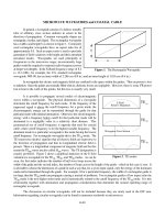
FIGURE 7.14 Photo of a prototype reconfigurable stretch-forming tool. The tool is comprised of > 2600 individual
servo-driven pins with spherical ends.
8596Ch07Frame Page 117 Tuesday, November 6, 2001 10:17 PM
© 2002 by CRC Press LLC
Other forms of resolution enhancement have been proposed. These include a sheet blankholder
(see Figure 7.7) that is either broken into independently controllable segments so that the frictional
restraining force can have several discrete values around the periphery of the sheet, or a deformable
blankholder with variable displacement supports
10
that allow a continuously variable (but spatially
band-limited) blankholder pressure distribution.
7.6 Direct Shape Feedback and Control
The special case shown in Figure 7.3 of direct feedback of part shape has recently found pre-
commercial application to stretch forming in the aerospace industry.
11
In this system the reconfig-
urable tool of Figure 7.14 is combined with a novel three-dimensional shape-sensing device and a
spatial frequency-based control law
11–13
to actuate the tool until shape errors are minimized (see
Figure 7.15). The actual control system has a minimum one forming cycle delay built in because
the part cannot be measured until after forming.
7.7 Summary
Control of metal-forming processes has advanced considerably with the advent of inexpensive
computer servo controls. However, the inherent sensitivity of the process to variations in the
constitutive properties of the workpiece materials prevents simple servo control of machine variables
from fully controlling the process output. Such control does, however, greatly reduce the process
variability, and with good production control of material and proper maintenance of the machine
and tooling, highly consistent and accurate parts can be produced at high rates. To move to the
next level of control where either the strains or final shapes are actively controlled involves a large
jump in sensing, actuation, and control law technology that has yet to emerge on the production floor.
References
1. Cao, J. and Boyce, M. C., A predictive tool for delaying wrinkling and tearing failures in sheet
metal forming, Journal of Engineering Materials and Technology (Transactions of the ASME)
(U.S.A.), 119(4), 354–365, October 1997.
2. Jalkh, P., Cao, J., Hardt, D., and Boyce, M. C., Optimal forming of aluminum 20008-T4 conical
cups using force trajectory control, Society of Automotive Engineers International, 11, 1993.
3. Traversin, M. and Kergen, R., Closed-loop control of the blankholder force in deep-drawing:
Finite-element modeling of its effects and advantages, Journal of Materials Processing Technology,
50(1–4), 306–317, 1 March 1995.
4. Majlessi, S. A. and Obermeyer, E. J., A review of recent advances in the application of blank-
holder force towards improving the forming limits of sheet metal parts, Journal of Materials
Processing Technology, 75(1), 222–234, 1998.
5. Parris, A. N., Precision Stretch Forming for Precision Assembly, Ph.D. thesis, Department of
Mechanical Engineering, Massachusetts Institute of Technology, 1996.
FIGURE 7.15 Shape control system using a reconfigurable tool and spatial frequency controller.
3D Shape
Measurement
Reference
Shape
Part Shape
-
Reconfigurable
Tool
Shape Control
Algorithm
Workpiece
8596Ch07Frame Page 118 Tuesday, November 6, 2001 10:17 PM
© 2002 by CRC Press LLC
6. Fenn, R. and Hardt, D. E., Real-time control of sheet stability during forming, ASME Journal of
Engineering for Industry, December 1993.
7. Manthey, D.W. and D. Lee, Recent developments in a vision-based surface strain measurement
system, Journal of Metals, 23(10), 46–49, July 1995.
8. Mermelstein, M. B., Feldkun, D. L., and Shirley, L. G., Video rate surface profiling with acousto-
optic accordian fringe interferometry, Journal of Optical Engineering, 39(1), 106–113, 2000.
9. West, J. S., Adaptive Stroke Reversal Control in Brakeforming, SM thesis, Department of Mechan-
ical Engineering, Massachusetts Institute of Technology, 1980.
10. Siegert, K., Hohnhaus, J., and Wagner, S., Combination of hydraulic multipoint cushion system
and segment-elastic blankholders, Developments in Sheet Metal Stamping, Proceedings of the
1998 SAE International Congress & Exposition, February 23–26, 1998, Detroit, MI.
11. Valjavec, M. and Hardt, D. E., Closed-loop shape control of stretch formed sheet metal parts using
a reconfigurable discrete die press, Sheet Metal 1998, Proceedings of the 6th International Con-
ference on Sheet Metal. Twente, The Netherlands, April 1998.
12. Hardt, D. E. and Webb R. D., A transfer function description of sheet metal forming for process
control, Transactions of the ASME, 113, 44–52, 1991.
13. Boyce, M. C., Hardt, D. E., Ousterhout, K. B., Karafillis, A., and Eigen, G., A CAD driven flexible
forming system for three-dimensional sheet metal parts, Proceedings of the SAE Congress, Sym-
posium on Sheet Forming, Detroit, March 1993.
8596Ch07Frame Page 119 Tuesday, November 6, 2001 10:17 PM
© 2002 by CRC Press LLC