Tài liệu Integrating Microsoft Exchange Server 2007 in a Cisco Multisite Data Center docx
Bạn đang xem bản rút gọn của tài liệu. Xem và tải ngay bản đầy đủ của tài liệu tại đây (2.75 MB, 86 trang )
Americas Headquarters
Cisco Systems, Inc.
170 West Tasman Drive
San Jose, CA 95134-1706
USA
Tel: 408 526-4000
800 553-NETS (6387)
Fax: 408 527-0883
Integrating Microsoft Exchange Server
2007 in a Cisco Multisite Data Center
Design
April 2, 2008
Customer Order Number:
Text Part Number: OL-15350-01
THE SPECIFICATIONS AND INFORMATION REGARDING THE PRODUCTS IN THIS MANUAL ARE SUBJECT TO CHANGE WITHOUT NOTICE. ALL
STATEMENTS, INFORMATION, AND RECOMMENDATIONS IN THIS MANUAL ARE BELIEVED TO BE ACCURATE BUT ARE PRESENTED WITHOUT
WARRANTY OF ANY KIND, EXPRESS OR IMPLIED. USERS MUST TAKE FULL RESPONSIBILITY FOR THEIR APPLICATION OF ANY PRODUCTS.
THE SOFTWARE LICENSE AND LIMITED WARRANTY FOR THE ACCOMPANYING PRODUCT ARE SET FORTH IN THE INFORMATION PACKET THAT
SHIPPED WITH THE PRODUCT AND ARE INCORPORATED HEREIN BY THIS REFERENCE. IF YOU ARE UNABLE TO LOCATE THE SOFTWARE LICENSE
OR LIMITED WARRANTY, CONTACT YOUR CISCO REPRESENTATIVE FOR A COPY.
The Cisco implementation of TCP header compression is an adaptation of a program developed by the University of California, Berkeley (UCB) as part of UCB’s public
domain version of the UNIX operating system. All rights reserved. Copyright © 1981, Regents of the University of California.
NOTWITHSTANDING ANY OTHER WARRANTY HEREIN, ALL DOCUMENT FILES AND SOFTWARE OF THESE SUPPLIERS ARE PROVIDED “AS IS” WITH
ALL FAULTS. CISCO AND THE ABOVE-NAMED SUPPLIERS DISCLAIM ALL WARRANTIES, EXPRESSED OR
IMPLIED, INCLUDING, WITHOUT
LIMITATION, THOSE OF MERCHANTABILITY, FITNESS FOR A PARTICULAR PURPOSE AND NONINFRINGEMENT OR ARISING FROM A COURSE OF
DEALING, USAGE, OR TRADE PRACTICE.
IN NO EVENT SHALL CISCO OR ITS SUPPLIERS BE LIABLE FOR ANY INDIRECT, SPECIAL, CONSEQUENTIAL, OR INCIDENTAL DAMAGES, INCLUDING,
WITHOUT LIMITATION, LOST PROFITS OR LOSS OR DAMAGE TO DATA ARISING OUT OF THE USE OR INABILITY TO USE THIS MANUAL, EVEN IF CISCO
OR ITS SUPPLIERS HAVE BEEN ADVISED OF THE POSSIBILITY OF SUCH DAMAGES.
Integrating Microsoft Exchange Server 2007 in a Cisco Multisite Data Center Design
© 2007 Cisco Systems, Inc. All rights reserved.
CCSP, CCVP, the Cisco Square Bridge logo, Follow Me Browsing, and StackWise are trademarks of Cisco Systems, Inc.; Changing the Way We Work, Live, Play, and Learn, and
iQuick Study are service marks of Cisco Systems, Inc.; and Access Registrar, Aironet, BPX, Catalyst, CCDA, CCDP, CCIE, CCIP, CCNA, CCNP, Cisco, the Cisco Certified
Internetwork Expert logo, Cisco IOS, Cisco Press, Cisco Systems, Cisco Systems Capital, the Cisco Systems logo, Cisco Unity, Enterprise/Solver, EtherChannel, EtherFast,
EtherSwitch, Fast Step, FormShare, GigaDrive, GigaStack, HomeLink, Internet Quotient, IOS, IP/TV, iQ Expertise, the iQ logo, iQ Net Readiness Scorecard, LightStream,
Linksys, MeetingPlace, MGX, the Networkers logo, Networking Academy, Network Registrar, Pack et , PIX, Post-Routing, Pre-Routing, ProConnect, RateMUX, ScriptShare,
SlideCast, SMARTnet, The Fastest Way to Increase Your Internet Quotient, and TransPath are registered trademarks of Cisco Systems, Inc. and/or its affiliates in the United States
and certain other countries.
All other trademarks mentioned in this document or Website are the property of their respective owners. The use of the word partner does not imply a partnership relationship
between Cisco and any other company. (0601R)
i
Integrating Microsoft Exchange Server 2007 in a Cisco Multisite Data Center Design
OL-15350-01
CONTENTS
Audience 1-1
Document Objectives 1-1
Document Format and Naming Conventions 1-2
Solution Overview 1-2
Solution Topology 1-2
Cisco Technology Overview 1-5
ACE Virtualization 1-5
Application Control Engine Global Site Selector 1-9
Cisco Content Network Registrar 1-10
Wide Area Application Engine 1-11
Microsoft Exchange Server 2007 Overview 1-12
Microsoft Exchange 2007 Server Roles 1-12
Microsoft Active Directory and Multisite Data Centers 1-15
Tested Microsoft Exchange Server 2007 Deployment Models 1-19
Microsoft Exchange Server 2007 Layout 1-19
Single-Site AD with Stretched CCR 1-20
Multisite Active Directory—Local CCR + Remote SCR 1-31
Optimization and Availability Support for Microsoft Exchange Server 2007 in a Cisco Multisite Data
Center
1-36
Enterprise Network Architecture 1-37
Data Center Network Components 1-37
Front-End Network 1-37
Core Layer 1-38
Aggregation Layer 1-39
Access Layer 1-39
Back-End Network 1-40
SAN Core Layer 1-40
SAN Edge Layer 1-40
Branch Network Components 1-41
Multisite Data Center Components 1-42
Design and Implementation Details 1-43
Design Goals 1-43
Enterprise Data Center Design 1-43
Site Selection 1-45
Contents
ii
Integrating Microsoft Exchange Server 2007 in a Cisco Multisite Data Center Design
OL-15350-01
Route Health Injection 1-50
Layer 2 Extension 1-50
Enterprise Edge Design 1-52
Client Access Server Role 1-54
Edge Server Role 1-71
Appendix 1-76
ACE SSL Proxy Configuration 1-76
Outlook Anywhere Configuration 1-78
Client Access Server (CAS) 1-78
Outlook Client 1-80
Corporate Headquarters:
Copyright © 2007 Cisco Systems, Inc. All rights reserved.
Cisco Systems, Inc., 170 West Tasman Drive, San Jose, CA 95134-1706 USA
Integrating Microsoft Exchange Server 2007 in a
Cisco Multisite Data Center Design
This document provides design and configuration guidance for site and server load balancing, Secure
Sockets Layer (SSL)- offload and WAN optimization in a Microsoft Exchange Server 2007 environment
when it is deployed into a Cisco multisite data center architecture. An overview of the various Microsoft
Exchange Server 2007 roles and operations will be given to provide the reader some context as to how
the application environment is impacted in a multisite data center design.
Audience
This document is intended for network engineers and architects who need to understand both the basics
of a Microsoft Exchange environment and the design and configuration options for providing advanced
network services for Microsoft Exchange Server 2007.
Document Objectives
The objective of this document is to provide customers guidance on how to leverage a Cisco multisite
data center design to support a Microsoft Exchange Server 2007 environment. The document is not
meant to introduce the reader to basic Cisco data center design configurations nor is it meant to be a
resource to learn the details of Microsoft Exchange Server 2007. The reader must be familiar with the
basic Cisco data center concepts and products as well as the basics of Microsoft Exchange Server 2007
components, roles, and deployment scenarios as documented by Microsoft Corporation. The
prerequisite knowledge can be acquired through many documents and training opportunities available
both through Cisco and Microsoft. Below are a few recommended information resources that readers
would find useful in these areas of interest:
Cisco Connection Online – Data Center:
/>Cisco Solution Reference Network Designs (SRND):
/>Microsoft Exchange Server 2007:
2
Integrating Microsoft Exchange Server 2007 in a Cisco Multisite Data Center Design
OL-15350-01
Solution Overview
Document Format and Naming Conventions
User-defined properties such as access control list names and policy definitions are shown in ALL CAPS
to assist the reader in understanding what is user-definable versus command specific. All commands are
shown in Courier font. All commands that are applicable to the section covered will be in BOLD.
Solution Overview
The multisite solution described in this document equally applies across financial, manufacturing,
consumer or information-based industries interested in constructing and deploying efficient and
productive data centers. Data centers house the applications and information critical to the business,
whatever that may be. Today, enterprises recognize that a data center is more than racks of compute
power, but an asset with the potential to provide a competitive edge. As a result, industries are
reevaluating their data center deployments with an interest to consolidate or expand where necessary to
address the following:
• New infrastructure including network and compute resources (64-bit platforms, blade servers,
switches, and routers)
• Regulatory compliance (typically resulting in expanded security and storage infrastructure)
• Facility space, power, and cooling to support new infrastructure
• New application environments and performance expectations
• Disaster recovery
The multisite solution described in this document focuses on the expectations of the application of four
fundamental design goals:
• Application high availability
• Application scalability
• Data and application security
• Application performance
This document highlights network-based technologies used within and between data centers to achieve
these objectives.
Solution Topology
Figure 1 depicts the Microsoft Exchange Server 2007 solution topology tested, where two distinct data
centers (Data Center 1 and Data Center 2) are deployed leveraging Cisco's infrastructure design best
practices. Note that each site provides local redundancy, scalability, and security for the applications it
hosts. A multisite solution should simply extend the functionality of a single-site and should not
compromise the integrity of either.
At each site in Figure 1, the hub and mailbox servers leverage the Layer 2 and 3 services of a well
designed access and aggregation layer. The access and aggregation layers consist of the Cisco Catalyst
6500s with Sup720s. In the aggregation layer of each site, a pair of Cisco 7200 routers with NPE-G2s
provide an L2TPv3 tunnel. This tunnel establishes Layer 2 adjacency between sites on a per-VLAN
basis, efficiently meeting the requirements of our Exchange Server 2007 environment while controlling
3
Integrating Microsoft Exchange Server 2007 in a Cisco Multisite Data Center Design
OL-15350-01
Solution Overview
spanning tree domain creep. The L2TPv3 tunnel traverses the core layer, which is a high-speed Layer 3
fabric consisting of the Cisco Catalyst 6500s with Sup720s. The red lines indicate the use of 10
GigabitEthernet throughout the access, aggregation, and core layers.
Figure 1 defines two points of access into the data center for remote users via the WAN or the Internet.
The remote branch users in the WAN benefit from the transparent and symmetric application
optimization services of the Cisco Wide Area Application Services (WAAS). Cisco Wide Area
Application Engines (WAEs) are located at each site and at the remote branch. Users originating from
the Internet connect via a DMZ local to each data center site. The DMZ consists of Cisco Catalyst 6500s
with Sup720s housing the Cisco Application Control Engine (ACE) service module, which provides
application and security services. The Exchange edge and CAS roles reside in this location. In addition,
the Internet edge houses a cluster of Cisco ACE Global Site Selectors (GSS), which monitor the state of
each data center's Exchange application environment and uses this knowledge to provide intelligent
selection between sites.
4
Integrating Microsoft Exchange Server 2007 in a Cisco Multisite Data Center Design
OL-15350-01
Solution Overview
This document discusses each of the areas defined in Figure 1 to provide a better understanding of the
application and the network deployed to support it.
Figure 1 Solution Topology
Hub
Access
Layer
Data Center 1 Data Center 2
Aggregation
Layer
Core
Layer
Internet
WAN
Hub
Edge
WAN
Agg
ACE
GSS
Internet
DC Edge
CAS
Branch Branch
Layer 2 Tunnel
MailboxMailbox Hub Hub
Edge
WAN
Agg
WAE
Farm
CAS
MailboxMailbox
222766
ACE
GSS
WAE
Farm
5
Integrating Microsoft Exchange Server 2007 in a Cisco Multisite Data Center Design
OL-15350-01
Solution Overview
Cisco Technology Overview
This section provides an overview of the main Cisco products and technologies used in this design. The
following products are addressed:
• Cisco Application Control Engine (ACE)
• Cisco ACE Global Site Selector (ACE GSS)
• Cisco Wide Area Application Engine (WAE)
The Cisco ACE provides a highly available and scalable data center solution from which the Microsoft
Exchange Server 2007 application environment can benefit. Currently, the Cisco ACE is available as an
appliance or integrated service module in the Cisco Catalyst 6500 platform. The Cisco ACE features and
benefits include the following:
• Device partitioning (up to 250 virtual ACE contexts)
• Load balancing services (up to 16 Gbps of throughput capacity and 345,000 L4 connections/second)
• Security services via deep packet inspection, access control lists (ACLs), unicast reverse path
forwarding (uRPF), Network Address Translation (NAT)/Port Address Translation (PAT) with
fix-ups, syslog, and so on
• Centralized role-based management via Application Network Manager (ANM) GUI or CLI
• SSL-offload (up to 15,000 SSL sessions via licensing)
• Support for redundant configurations (intra-chassis, inter-chassis, and inter-context)
The following sections describe some of the Cisco ACE features and functionalities used in the
Microsoft Exchange Server 2007 application environment.
ACE Virtualization
Virtualization is a prevalent trend in the enterprise today. From virtual application containers to virtual
machines, the ability to optimize the use of physical resources and provide logical isolation is gaining
momentum. The advancement of virtualization technologies includes the enterprise network and the
intelligent services it offers.
The Cisco ACE supports device partitioning where a single physical device may provide multiple logical
devices. This virtualization functionality allows system administrators to assign a single virtual ACE
device to a business unit or application to achieve application performance goals or service-level
agreements (SLAs). The flexibility of virtualization allows the system administrator to deploy
network-based services according to the individual business requirements of the customer and technical
requirements of the application. Service isolation is achieved without purchasing another dedicated
appliance that consumes more space and power in the data center.
Figure 2 shows the use of virtualized network services afforded via the Cisco ACE and Cisco Firewall
Services Module (FWSM). In Figure 2, a Cisco Catalyst 6500 housing a single Cisco ACE and FWSM
supports the business processes of five independent business units. The system administrator determines
the application requirements and assigns the appropriate network services as virtual contexts. Each
context contains its own set of policies, interfaces, resources, and administrators. The Cisco ACE and
FWSMs allow routed, one-arm, and transparent contexts to co-exist on a single physical platform.
6
Integrating Microsoft Exchange Server 2007 in a Cisco Multisite Data Center Design
OL-15350-01
Solution Overview
Figure 2 Service Chaining via Virtualized Network Services
Note For more information on ACE virtualization, see the Application Control Engine Module Virtualization
Configuration Guide at the following URL:
/>a00806882c6.html
SSL-Offload
The Cisco ACE is capable of providing secure transport services to applications residing in the data
center. The Cisco ACE implements its own SSL stack and does not rely on any version of OpenSSL.
The Cisco ACE supports TLS 1.0, SSLv3, and SSLv2/3 hybrid protocols. There are three SSL relevant
deployment models available to each ACE virtual context:
221232
BU-2
Aggregation Switch
One Arm Mode
Service Chain
Routed Mode
Service Chain
Routed Mode
Service Chain
No Service
Chain
Transparent
Service Chain
Transparent
Service Chain
BU-3BU-1 BU-5 BU-6BU-4
One Arm
VLAN 99
VLAN 6
VLAN 60
VLAN 5
VLAN 15VLAN 4
VLAN 55
VLAN 33
VLAN 22 VLAN 225
VLAN 3
7
Integrating Microsoft Exchange Server 2007 in a Cisco Multisite Data Center Design
OL-15350-01
Solution Overview
• SSL termination—Allows for the secure transport of data between the client and ACE virtual
context. The Cisco ACE operates as an SSL proxy, negotiating and terminating secure connections
with a client and a non-secure or clear text connection to an application server in the data center.
The advantage of this design is the offload of application server resources from taxing the CPU and
memory demands of SSL processing, while continuing to provide intelligent load balancing.
• SSL initiation—Provides secure transport between the Cisco ACE and the application server. The
client initiates an unsecure HTTP connection with the ACE virtual context, the Cisco ACE acting as
a client proxy negotiates an SSL session to an SSL server.
• SSL end-to-end—Provides a secure transport path for all communications between a client and the
SSL application server residing in the data center. The Cisco ACE uses SSL termination and SSL
initiation techniques to support the encryption of data between client and server. Two completely
separate SSL sessions are negotiated, one between the ACE context and the client, the other between
the ACE context and the application server. In addition to the intelligent load balancing services the
Cisco ACE provides in an end-to-end SSL model, the system administrator may choose to alter the
intensity of data encryption to reduce the load on either the front-end client connection or back-end
application server connection to reduce the SSL resource requirements on either entity.
SSL URL Rewrite Offload
The Cisco ACE is capable of inserting or deleting HTTP header information for connections it is
sustaining. This capability is highly useful when an application server responds with a HTTP 302 or
“Moved Temporarily” response to a client's HTTP GET or HEAD request. The HTTP 302 response
usually indicates a new HTTP LOCATION URL for the client to access. Modifying the HTTP
LOCATION value for a secure connection is known as SSL URL rewrite. The SSL URL Rewrite feature
allows the system administrator to alter the HTTP LOCATION value returned to the client resulting in
granular control of the application's session flow and persistence in the data center.
SSL Session ID Reuse
SSL session ID reuse allows the client and server to reuse the secret key negotiated during a previous
SSL session. This feature generally improves the volume of SSL sessions that an SSL server or SSL
proxy can effectively maintain. Clients residing with remote connectivity, for instance across a WAN,
generally benefit from this feature. The SSL negotiation load is effectively reduced on the SSL proxy
server while simultaneously improving the user experience as key negotiation is a rather lengthy process.
The Cisco ACE may maintain the SSL session ID indefinitely or up to 20 hours with a timeout
configuration.
It should be noted that SSL ID reuse does not compromise the security of the data center. The ID reuse
feature only acknowledges that a secret key already exists between the client and server. Nonetheless the
client must leverage this key for the application server to receive data from the client. The security
resides in the secret key not the SSL session ID.
Session Persistence
Session persistence is the ability to forward client requests to the same server for the duration of a
session. Microsoft supports session persistence for their Microsoft Exchange environment via the
following methods:
• Source IP sticky
• Cookie sticky
The Cisco ACE supports each of these methods, but given the presence of proxy services in the
enterprise, Cisco recommends using the cookie sticky method to guarantee load distribution across the
server farm wherever possible as session-based cookies present unique values to use for load balancing.
8
Integrating Microsoft Exchange Server 2007 in a Cisco Multisite Data Center Design
OL-15350-01
Solution Overview
The following example shows the sessionid cookie inserted into the client’s Microsoft Exchange request
via the Set-Cookie command from the server. It is also possible to insert cookies into the HTTP header
via the Cisco ACE.
(Status-Line):HTTP/1.1 302 Moved Temporarily
Set-Cookie:aceoptimized=R3191602213; path=/
Location: />son=0
Set-Cookie:sessionid=; path=/; expires=Thu, 01-Jan-1970 00:00:00 GMT
Set-Cookie:cadata=; path=/; expires=Thu, 01-Jan-1970 00:00:00 GMT
Connection:close
Content-Length:0
In addition, the Cisco ACE supports the replication of sticky information between devices and their
respective virtual contexts. This provides a highly available solution that maintains the integrity of each
client's session.
Allowed Server Connections
Enterprise data centers should perform due diligence on all deployed server and network devices,
determining the performance capabilities to create a more deterministic, robust, and scalable application
environment. The Cisco ACE allows the system administrator to establish the maximum number of
active connections values on a per-server basis and/or globally to the server farm. This functionality
protects the end device, whether it is an application server or network application optimization device
such as the WAE.
Route Health Injection
Route Health Injection (RHI) allows the Cisco ACE to advertise host routes associated with any number
of virtual IP addresses hosted by the device. The injection of the host route to the remaining network
offers Layer 3 availability and convergence capabilities to the application environment.
KAL-AP UDP Agent
The Cisco ACE supports the KeepAlive-Appliance Protocol (KAL-AP) via a local UDP agent. This
agent responds to KAL-AP queries from site selectors, such as the Cisco Global Site Selector, to provide
the status and workload associated with one or more virtual IP addresses maintained by an ACE virtual
context. The KAL-AP agent supports both domain and tagged formed queries. Tagged formed queries
allow the verification of VIP state across NAT devices, such as firewalls or routers, and multiple ports
for the same virtual IP address. This real-time information provides a more robust and accessible
application as load and availability information may be leveraged to distribute traffic intelligently across
multiple enterprise sites.
Health Monitoring
The Cisco ACE device is capable of tracking the state of a server and determining its eligibility for
processing connections in the server farm. The Cisco ACE uses a simple pass/fail verdict but has many
recovery and failures configurations, including probe intervals, timeouts, and expected results. Each of
these features contributes to an intelligent load-balancing decision by the ACE context.
Following are the predefined probe types currently available on the ACE module:
• ICMP
• TCP
• UDP
9
Integrating Microsoft Exchange Server 2007 in a Cisco Multisite Data Center Design
OL-15350-01
Solution Overview
• Echo (TCP/UDP)
• Finger
• HTTP
• HTTPS (SSL Probes)
• FTP
• Telnet
• DNS
• SMTP
• IMAP
• POP
• RADIUS
• Scripted (TCL support)
Note that the potential probe possibilities available via scripting make the Cisco ACE an even more
flexible and powerful application-aware device. In terms of scalability, the Cisco ACE module can
support 1000 open probe sockets simultaneously.
Application Control Engine Global Site Selector
Overview
The Cisco Application Control Engine Global Site Selector (Cisco ACE GSS) is an appliance that offers
failover protection via Global Server Load Balancing (GSLB). The Cisco GSS device allows the
enterprise to distribute and balance workload across multiple sites, providing the following benefits:
• Work-load distribution
• Disaster recovery and failover protection
• Improved user experience
• DNS offload
The Cisco GSS becomes part of the enterprise's DNS routing hierarchy as the authoritative DNS server
for those services under its domain. The Cisco GSS intelligently resolves DNS requests with the
additional knowledge of the site's availability and the associated application's state. This knowledge is
gained from tight integration with load-balancers such as the Cisco Content Services Switch (CSS),
Cisco Content Switch Module (CSM), and the Cisco ACE. Each of these load-balancers monitor the
state of local application servers and communicate this information to the Cisco GSS where a global
enterprise aware decision can be made. Currently, the Cisco GSS can support approximately 4,000
virtual IP addresses. The Cisco GSS includes the following factors prior to responding to a DNS request:
• Availability
• Proximity
• Load
• Source of the request (DNS proxy)
• Preference
10
Integrating Microsoft Exchange Server 2007 in a Cisco Multisite Data Center Design
OL-15350-01
Solution Overview
Note The Cisco GSS device may also monitor individual servers, IOS SLB devices, DRP-enabled routers,
Cisco's Local Director, and Cisco cache engines.
Keepalives
The Cisco GSS leverages keepalives to determine the state of a particular VIP under its domain. The
Cisco GSS supports the following keepalive types:
• ICMP
• TCP
• HTTP HEAD
• KeepAlive-Appliance Protocol (KAL-AP)
• Scripted Keepalives
• Name Server
These keepalive types can be used individually or in a multiport group to determine the status of a virtual
IP address. As a rule, the Cisco GSS does not respond to a DNS query with a VIP that has been declared
inactive.
The KAL-AP keepalive is particularly useful when the Cisco network load-balancing technology is
present. The Cisco GSS queries the load-balancer at each site for VIP state and load information. The
detailed response received by the Cisco GSS from the network load-balancer can be used to distribute
load efficiently across sites.
Note The keepalive timers may be adjusted to establish an acceptable failure window for the enterprise.
Cisco Content Network Registrar
The Cisco Content Network Registrar (CNR) is a separate process running on the GSS appliance that
provides both DNS and DHCP support. As a full-featured DNS server, the CNR maintains the resource
records (RR) within each enterprise DNS zone it supports. Mail Exchange (MX) resource records are
of particular importance for an enterprise messaging application. MX records provide a list of
hostnames providing mail exchange services within a domain. The CNR subsystem provides the MX
functionality required for successful messaging.
Note For more information on the Cisco Content Network Registrar, refer to:
For more information on the Cisco Global Site Selector, refer to:
11
Integrating Microsoft Exchange Server 2007 in a Cisco Multisite Data Center Design
OL-15350-01
Solution Overview
Wide Area Application Engine
To appreciate how the Cisco Wide Area Application Services (WAAS) provides WAN and application
optimization benefits to the enterprise, consider the basic types of centralized application messages that
are transmitted between remote branches. For simplicity, two basic types are identified:
• Bulk transfer applications—Transfer of files and objects, such as FTP, HTTP, and IMAP. In these
applications, the number of roundtrip messages may be few, and may have large payloads with each
packet. Examples include web portal or thin client versions of Oracle, SAP, Microsoft (SharePoint,
OWA) applications, e-mail applications (Microsoft Exchange, Lotus Notes), and other popular
business applications.
• Transactional applications—High number of messages transmitted between endpoints. Chatty
applications with many round-trips of application protocol messages that may or may not have small
payloads.
The Cisco WAAS uses the technologies described in the following subsections to provide a number of
features, including application acceleration, file caching, print service, and DHCP to benefit both types
of applications.
Advanced Compression Using DRE and Lempel-Ziv Compression
Data Redundancy Elimination (DRE) is an advanced form of network compression that allows the Cisco
WAAS to maintain an application-independent history of previously-seen data from TCP byte streams.
Lempel-Ziv (LZ) compression uses a standard compression algorithm for lossless storage. The
combination of using DRE and LZ reduces the number of redundant packets that traverse the WAN,
thereby conserving WAN bandwidth, improving application transaction performance, and significantly
reducing the time for repeated bulk transfers of the same application.
Transport File Optimizations
The Cisco WAAS Transport File Optimizations (TFO) uses a robust TCP proxy to safely optimize TCP
at the WAE device by applying TCP-compliant optimizations to shield the clients and servers from poor
TCP behavior because of WAN conditions. The Cisco WAAS TFO improves throughput and reliability
for clients and servers in WAN environments through increases in the TCP window sizing and scaling
enhancements as well as implementing congestion management and recovery techniques to ensure that
the maximum throughput is restored if there is packet loss.
Common Internet File System Caching Services
Common Internet file system (CIFS), used by Microsoft applications, is inherently a highly chatty
transactional application protocol where it is not uncommon to find several hundred transaction
messages traversing the WAN just to open a remote file. The Cisco WAAS provides a CIFS adapter that
can inspect and to some extent predict what follow-up CIFS messages are expected. By doing this, the
local WAE caches these messages and sends them locally, significantly reducing the number of CIFS
messages traversing the WAN.
Print Services
The Cisco WAAS provides native SMB-based Microsoft print services locally on the WAE device. Along
with CIFS optimizations, this allows for branch server consolidation at the data center. Having
full-featured local print services means less traffic transiting the WAN. Without the Cisco WAAS print
services, print jobs are sent from a branch client to the centralized server(s) across the WAN, and then
back to the branch printer(s), thus transiting the WAN twice for a single job. The Cisco WAAS eliminates
the need for either WAN trip.
12
Integrating Microsoft Exchange Server 2007 in a Cisco Multisite Data Center Design
OL-15350-01
Microsoft Exchange Server 2007 Overview
Note For more information on these enhanced services, see the Cisco Wide Area Application Services (WAAS)
V4.0 Technical Overview at the following URL:
Microsoft Exchange Server 2007 Overview
The Microsoft Exchange Server 2007 offers many advantages to customers in the form of built-in
protection, flexible access methods and operational efficiency. Customers are looking for ways to cut
cost and increase productivity while ensuring that there is high availability. Microsoft Exchange Server
2007 was designed to offer solutions to these most demanding customer messaging requirements and do
so for a variety of endpoints, from any location and to provide access to messaging resources in a secure
and highly available manner.
Some of these customer requirements are met by enabling the following:
• Integrated message filtering
• Business continuance via several clustering and disaster recovery options
• Endpoint security for a variety of access methods which include a web client, Outlook, mobile, and
POP/IMAP
• Flexible policy creation, management and reporting for legal compliance needs
• Streamlined setup, administration and management via the Microsoft Exchange Management
Console, Exchange Management Shell, and Systems Center products
• Scalability and performance improvements through a x64-based architecture, increased memory
support, and more intelligent message routing
There are many feature improvement and advantages of using Microsoft Exchange Server 2007 as well
as comparisons with Microsoft Exchange Server 2003. Additional information on these features,
advantages and comparisons can be found at:
Microsoft Exchange Server 2007 requires an existing Microsoft Active Directory (AD) deployment and
leverages AD as a means to store and share information within the Exchange environment. More
information regarding the planning and deployment of Microsoft Active Directory in support of
Exchange Server 2007 can be found here:
/>Note All references to Exchange Server 2007 used in testing imply the most up-to-date version of Exchange
at time of validation, which is Exchange Server 2007 Service Pack 1 (SP1).
Microsoft Exchange 2007 Server Roles
There are five roles in Microsoft Exchange Server 2007. Each role serves a unique purpose within the
Microsoft Exchange architecture and is flexible enough to be deployed in various sized organizations
with varying requirements.
All roles (except Edge Transport) can be installed together on a single platform or can be deployed
completely independent of one another. Small-medium customers can leverage the diverse number of
Microsoft Exchange Server 2007 features while limiting the amount of hardware required for
13
Integrating Microsoft Exchange Server 2007 in a Cisco Multisite Data Center Design
OL-15350-01
Microsoft Exchange Server 2007 Overview
deployment by deploying the roles on the same server. Large organizations can leverage having multiple
roles deployed in a redundant fashion on independent hardware platforms in geographically dispersed
locations.
The five roles in Microsoft Exchange Server 2007 are:
• Client Access Server (CAS)
• Hub Transport (HT)
• Mailbox Server (MBX)
• Edge Transport (ET)
• Unified Messaging (UM)
The following sections will describe four of the five roles at a high-level and is not meant to be a full
tutorial on the architecture, design, and operation of each role. The UM role is the only role that was not
tested in the Cisco multisite data center design due to time constraints. A future version of this document
will include the UM role in the Cisco multisite data center design. Detailed information on the Microsoft
Exchange Server 2007 product, architecture, and design is found at:
or
Client Access Server
The client access server (CAS) provides access for a variety of client endpoints. The CAS role was
formerly known as the Exchange front-end server. The CAS role supports access via the following
methods:
• Microsoft Outlook Web Access (OWA)
• Post Office Protocol Version 3 (POP3)
• Internet Message Access Protocol Version 4 (IMAP4)
• Microsoft Exchange ActiveSync client
• Microsoft Outlook Anywhere
The CAS role also supports various other web services such as the offline address book (OAB)
distribution and the autodiscover service. The list above shows that the CAS role can provide access to
messaging services via many different endpoint types such as computers with web browsers, Outlook
outside of the corporate firewall, email clients using POP3/IMAP4 and even mobile devices. Endpoints
using another method of access such as Messaging Application Programming Interface (MAPI) most
often connect directly to the mailbox server (MBX) role while within the corporate firewall (see
Mailbox
Server, page 14).
In the simplest terms, the CAS role provides a front-end service for the MBX role for non-MAPI
connections. The CAS communicates directly with the MBX. The CAS role is optional if there are no
requirements to use non-MAPI clients.
Microsoft recommends to deploy multiple CAS for performance, scalability, and availability purposes.
The Microsoft Exchange Server 2007 fully supports multiple CAS role servers to be active
simultaneously. This is ideal for an active/active multisite data center design.
Hub Transport Server
The Hub Transport (HT) role, formerly known as the Bridgehead server, is the central role for intelligent
message routing delivery and policy control. Unlike the CAS and Edge Transport (ET) roles, the HT is
required.
14
Integrating Microsoft Exchange Server 2007 in a Cisco Multisite Data Center Design
OL-15350-01
Microsoft Exchange Server 2007 Overview
All mail flow external to the organization and internal within the organization is handled by the HT role.
The HT role can use the ET as an SMTP relay for messages going to/from the Internet or it can handle
the SMTP relay role on its own. The HT communicates directly with the MBX, other HT roles, and the
ET.
Messaging routing within the Microsoft Exchange environment is requires the configuration of Active
Directory (AD). AD is used to ensure that optimal message routing is accomplished within and between
AD sites. This is quite different from previous Microsoft Exchange versions where routing groups were
the primary method for messaging routing.
As was the case with the CAS role, it is recommended by Microsoft to deploy multiple HT roles for
performance, scalability and availability purposes. Microsoft Exchange Server 2007 fully supports for
the HT role to have multiple servers active simultaneously. This is ideal for an active/active multisite
data center design.
Mailbox Server
The mailbox server (MBX) role is the database for all user messaging data. Users are homed to a
particular MBX and associated storage group. As mentioned before, MAPI-based clients such as those
running Microsoft Outlook connect directly to the MBX while within the corporate firewall. The MBX
role is a required component of an Exchange Server 2007 deployment.
Microsoft Exchange Server 2007 has several options for maintaining high availability (HA) of the MBX
role to include Local Continuous Replication (LCR), Cluster Continuous Replication (CCR), Standby
Continuous Replication (SCR – Service Pack 1-only) and Single Copy Cluster (SCC). For more
information on these solutions refer to the following URL:
The two HA solutions that are discussed in this document are CCR and SCR. CCR is used to provide a
two-node cluster of the mailbox role that allows for either automatic failover or manual failover of the
cluster nodes. SCR allows for multiple standby nodes to pull mailbox logs from the primary MBX to
provide disaster recovery (DR) and also mailbox database portability. SCR is a great choice for
geographically dispersed data centers as well as for providing a way to replicate mailbox data to multiple
data centers simultaneously. The two solutions (CCR and SCR) can be used together.
The MBX role is the only Exchange Server 2007 role that does not support an active/active
configuration. However, the MBX role is also the only role that supports clusters. Therefore, more than
one MBX can be deployed for scalability and availability purposes, but a user can only be connected to
a single MBX that user is associated with. As will be discussed later on, if the primary MBX is
unavailable, a standby server located within the same or different data center can take over the role.
The MBX communicates directly with the CAS, HT and, if deployed, the standby node in a clustered
mailbox server (CMS).
Edge Transport Server
The Edge Transport (ET) role is used as a dedicated Internet SMTP relay as well as a means to provide
message hygiene. The ET can be used to filter messages (SPAM) and also provide virus protection at
the initial ingress point of the messaging system.
The ET leverages Active Directory but in a different way than the other roles. Active Directory
Application Mode (ADAM) is used to store recipient information for the exchange organization so that
the ET can know for which users it can accept mail. Since the ET is deployed at the network edge, it
should be deployed as securely as possible. In an effort to secure the internal AD information, the ET
has a one-way connection with the internal HT roles and uses an EdgeSync subscription as a method to
replicate internal AD information with the ADAM instance running on each ET. This allows recipient
information to be stored on the ET for mail acceptance purposes without exposing the internal AD
15
Integrating Microsoft Exchange Server 2007 in a Cisco Multisite Data Center Design
OL-15350-01
Microsoft Exchange Server 2007 Overview
topology and objects to an attacker if the server is compromised. Microsoft recommends that a
“perimeter” AD environment be deployed to help facilitate the management of common policies and
operations for the ET roles.
Microsoft recommends deploying multiple ET roles for performance, scalability and availability
purposes. Microsoft Exchange Server 2007 fully supports for the ET role to have multiple servers active
simultaneously. This is ideal for an active/active multisite data center design.
Figure 3 shows a high-level view of the four tested Microsoft Exchange 2007 Server roles and a basic
traffic flow between each role.
Figure 3 High-level view of Microsoft Exchange Server 2007 roles
Microsoft Active Directory and Multisite Data Centers
As mentioned before, Microsoft Active Directory plays a critical and required role in the Microsoft
Exchange Server 2007 environment. In the testing conducted by Cisco, there were two AD deployment
options that were used between data centers. The first was using a single AD site for two active data
center locations and the second was using an AD site for each data center location by using the Microsoft
Active Directory Sites and Services capability to create and manage AD replication between sites.
Note All designs and references in this document are based on using Microsoft Windows Server 2003 R2 SP2.
Microsoft Exchange Server 2007 with SP1 supports the upcoming release of Microsoft Windows Server
2008. However, at the time of publication of this document, Windows Server 2008 is not shipping.
Future updates to this document will include the architectural changes to the presented designs when
Windows Server 2008 is commercially available and has been tested by Cisco.
Single AD Site — Multiple Data Center Locations
There are many things to consider in a “normal” AD deployment model that will determine the success
or failure of a scalable and available AD implementation. Adding the additional issues involved with
now spanning a single AD site to multiple physical locations that can be geographically dispersed by
great distance may be too great for many customers to undergo. Some, but certainly not all, of the
considerations that a customer needs to account for are:
Enterprise Site
Internet
CAS Mailbox
Edge Transport
External Communications
Internal Exchan
g
e Communications
SMTP
Messages
Remote Clients
(OWA, ActiveSync,
Anywhere,
POP3, IMAP4)
Hub Transport
MAPI
Mail Client
222767
16
Integrating Microsoft Exchange Server 2007 in a Cisco Multisite Data Center Design
OL-15350-01
Microsoft Exchange Server 2007 Overview
• Available network bandwidth and latency between each data center
• Suitable AD replication schedule between domain controllers/global catalog servers
• Contention between AD replication and other application/network traffic between data centers
• Containment of AD objects to a local site for management and security purposes
The considerations listed above will most often dictate that the data centers are close enough to each
other to provide adequate bandwidth and low latency.
Note This document is not intended to provide the required knowledge for AD planning and implementation
for Microsoft Exchange Server 2007. Additional information related to AD requirements for Exchange
Server 2007 can be found at: />The single AD site model was used and tested as it was the best model to allow for nearly all Microsoft
Exchange Server 2007 components to function in an active/active role. As mentioned before, the
mailbox server role is the only role that cannot support load balancing and/or active/active
configurations. The CAS, HT and ET roles can support an active/active data center deployment. The
reader must research and understand the Microsoft AD and Exchange Server 2007 implications of such
a design before considering it for deployment.
Figure 4 shows a high-level overview of the single AD site model as it resides within two active data
centers. The dashed box indicates that both DC locations are within the same single AD site. The only
role in this scenario that cannot support an active/active configuration is the mailbox server role. In this
example, the Microsoft Exchange Server 2007 Continuous Cluster Replication (CCR) feature is used to
cluster the mailbox server role with the active Clustered Mailbox Server (CMS) in the primary DC and
the standby CMS in the secondary DC. All other roles shown can be active in both DC locations
simultaneously.
Figure 4 Single Active Directory Site with Stretched CCR—Two Data Center Locations
Data Center 1
Single Active Directory Site
Internet
Edge
DC/GC
Hub
CAS
Active
CMS
Data Center 2
Edge
DC/GC
Hub
CAS
Standby
CMS
222768
17
Integrating Microsoft Exchange Server 2007 in a Cisco Multisite Data Center Design
OL-15350-01
Microsoft Exchange Server 2007 Overview
Multiple AD Sites—Multiple Data Centers
While the single AD site model allows for the ability to have most Exchange Server 2007 roles in an
active/active configuration, the requirements for supporting such a design may outweigh the advantages.
As discussed in
Single AD Site — Multiple Data Center Locations, there are many considerations to plan
for when dealing with a single AD site model for Exchange Server 2007. The AD, Exchange, and
network administrators must balance the active use of resources in all data center locations against the
management and cost associated with the support of full active-use of each resource in each location.
The model of supporting at least one AD site per data center location is easier to plan and deploy as well
as support, especially when the data centers are geographically dispersed. If the primary goal is that of
site-wide disaster recovery versus load balancing between sites, the multiple AD site model is more
appropriate. With that said, it is possible to have some roles of the Exchange Server 2007 deployment
be active/active in the multiple AD site model. The following are two examples of using an active/active
configuration with multiple AD sites:
• CAS Deployment—A deployment may have multiple CAS roles per DC location and each DC has
one or more AD sites. If site load balancing directs a user request to a CAS role located in a different
DC (subsequently a different AD site) than the user belongs to, a feature known as CAS-CAS
proxying can still connect the user to the correct CAS role for their site which then connects to the
correct mailbox server. This feature allows for the CAS roles to be active at both DC locations.
More information can be found on CAS-CAS proxying at:
• Edge Transport Deployment—Using the above CAS deployment scenario where there are multiple
ET roles that are deployed in multiple DC locations, it is possible to allow all ET roles to be
operational at all DC locations. EdgeSync subscriptions are used to establish connectors between
HT and ET roles. The EdgeSync subscription connects the ET role to the HT role located in a
specific site. Based on this process, if a ET role receives mail that is meant for a mail recipient
located in different AD site than that ET role is subscribed to (via the Hub), the message is routed
to the local Hub which routes the message to the HT role in the destination AD site. This
configuration is described in more detail here:
Similar types of considerations exist for both single AD and multiple AD site models but are less
stringent for the multiple AD site model. Microsoft Active Directory Sites and Services is designed to
implement and deploy multiple AD sites, their resources and schedules for AD replication. As they
apply to AD and Exchange, bandwidth and latency requirements for the network are also less stringent
because the links between DC locations are mostly used for AD and Exchange Server 2007 Mailbox
replication versus full-time use for replication in addition to active/active traffic flow.
Depending on how the Exchange Server 2007 mailbox clustering is deployed, there are two common
ways to implement multiple AD sites between data centers:
• Stretched CCR—AD site per DC with the primary AD site stretched to include the passive node
mailbox server located in the second DC.
• Local CCR + Remote Standby Continuous Replication (SCR)—AD site per DC with both CCR
nodes at the primary DC and SCR node in the secondary DC.
There is more discussion on CCR and SCR in upcoming sections of this document.
18
Integrating Microsoft Exchange Server 2007 in a Cisco Multisite Data Center Design
OL-15350-01
Microsoft Exchange Server 2007 Overview
Figure 5 illustrates using Microsoft Exchange Server 2007 with a stretched CCR design between two
AD sites. There is one AD site per DC location but with the AD site from the primary location being
stretched across the Layer 2 DC-to-DC interconnect (not shown) to the standby DC location. This
stretched AD site design is required as Exchange CCR nodes must exist in the same logical AD site
regardless of which physical DC they reside in.
Figure 5 Multiple Active Directory Sites with Stretched CCR—Two Data Center Locations
Primary Data Center
Active Directory Site 1
Active Directory Site 2
Internet
Edge
DC/GC
Hub
CAS
Active
CMS
Secondary Data Center
Edge
DC/GC
Hub
CAS
Standby
CMS
222769
19
Integrating Microsoft Exchange Server 2007 in a Cisco Multisite Data Center Design
OL-15350-01
Microsoft Exchange Server 2007 Overview
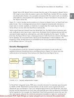
Figure 6 illustrates the use of Microsoft Exchange Server 2007 with a local CCR and remote SCR
implementation. There is one AD site per DC location and since the CCR implementation is local to the
primary site and no longer stretched, there is no need to also stretch the AD site for CCR between
physical DC locations. SCR offers an excellent way to provide mailbox server availability without
requiring alternative AD site designs.
Figure 6 Multiple Active Directory Sites with Local CCR + Remote SCR —Two Data Center
Locations
There are many decisions that need to be made in correct order when a server and/or site failure occurs.
Microsoft has a well documented flowchart that discusses what to do in the event of a resource or site
failure with Exchange Server 2007. The documentation can be found here:
Tested Microsoft Exchange Server 2007 Deployment Models
Microsoft Exchange Server 2007 Layout
There are many possible combinations of Exchange Server 2007 implementations. In this document,
two implementation examples are explored in more depth and have specific Cisco product, feature, and
design elements associated with both implementation examples. The two AD and Exchange Server 2007
implementation examples discussed in this document are:
• Single-Site AD with Stretched CCR—Two active/active data centers
• Multisite Active Directory—Local CCR + Remote SCR— Active/standby data centers
Primary Data Center
Active Directory Site 1
Active Directory Site 2
Internet
Edge
DC/GC
Hub
CAS
CCR Pair
Secondary Data Center
Edge
DC/GC
Hub
CAS
SCR
222770
20
Integrating Microsoft Exchange Server 2007 in a Cisco Multisite Data Center Design
OL-15350-01
Microsoft Exchange Server 2007 Overview
Single-Site AD with Stretched CCR
As discussed earlier, the goal of the single AD site with stretched CCR design is to support an
active/active data center design for Microsoft Exchange Server 2007. Having the Exchange roles in a
single logical AD site eliminates the complexity and delay of having to perform an AD “fix up” on
Exchange roles in the event of a site failure at the primary site. Since each Exchange role is within a
single AD site, nothing within AD has to be done in the event of failure at either site to allow Exchange
to continue operating.
The AD layout of this design is discussed in the previous section and illustrated in Figure 4. The
following section is more focused on the Exchange Server 2007 roles, their locations within the two data
centers, and specific Exchange considerations for supporting the stretched CCR design.
Client Access Server—Active/Active DC
Multiple Microsoft Exchange 2007 servers running the CAS role are used not only to provide fault
tolerance for individual server failures and scalability to support larger volumes of sessions, but also to
provide a means for supporting local site load balancing as well as geographical load balancing between
sites.
In addition to being an ideal candidate for server and site load balancing, the CAS role can additionally
take advantage of network optimization services and SSL-offloading.
In Figure 7, a total of four Exchange are running the CAS role are deployed at the two DC locations. In
this example, the CAS role has been deployed at the Internet DC (IDC) edge in a DMZ context that is
specifically configured for the CAS role and services both internal and external client connections.
Optionally, CAS roles can be deployed within the internal enterprise DC for internal CAS services while
Internet-facing CAS roles service clients that are externally located. Both deployment options are
supported in a Cisco multisite data center solution.
21
Integrating Microsoft Exchange Server 2007 in a Cisco Multisite Data Center Design
OL-15350-01
Microsoft Exchange Server 2007 Overview
Figure 7 CAS Deployment – Active/Active Data Center
The numbered objects in Figure 7 correspond to the areas where the CAS role can interoperate with
networking services.
1. Site selection and load balancing for each of the CAS Web (OWA, Outlook Anywhere,
Autodiscover, etc…) and non-Web (POP3/IMAP4) services via the Cisco Global Site Selector
product or generic DNS round-robin.
2. The Cisco ASA or FWSM can be used to provide firewall services. The Cisco ACE module can be
deployed for Layer 4 through Layer 7 load balancing and can monitor the health of the CAS services
and intelligently balance traffic amongst multiple CAS roles as well as report availability to the
Cisco GSS. Also, at the same location, SSL-offload can be performed on the CAS role to help scale
services such as OWA which uses HTTPS. The SSL-offload features of the Cisco ACE can help
reduce CPU utilization on the CAS role by offloading the encryption/decryption process for each
individual HTTPS session.
3. If branch office users connect to the CAS services located at either of the active data center
locations, the Cisco WAE product can perform WAN optimization on the sessions to reduce
bandwidth utilization, optimize the TCP sessions and reduce or eliminate duplicate data being
transmitted between sites. It is important to note that the Microsoft Exchange and network
administrators work together to understand the PROS and CONS of optimizing CAS services by
Data Center 1
Redundant External Firewalls
Redundant Internal Firewalls
Branch Offices
Redundant Server
Load-Balancers
Internet
IP Network
CAS
Outlook Web Access
Outlook Anywhere
CAS
Active
CCR CMS
Data Center 2
Site
Load-Balancing
222771
CASCAS
1
2
3 3
2
Standby
CCR CMS