Tài liệu Cảm biến trong sản xuất P11 doc
Bạn đang xem bản rút gọn của tài liệu. Xem và tải ngay bản đầy đủ của tài liệu tại đây (2.38 MB, 37 trang )
4.4
Abrasive Processes
I. Inasaki, B. Karpuschewski, Keio University, Yokohama, Japan
4.4.1
Introduction
Abrasive processes, which are mostly applied for achieving high accuracy and
high quality of mechanical, electrical, and optical parts, can be divided into two
categories, fixed abrasive processes and loose abrasive processes. In fixed abrasive
processes, grinding wheels or honing stones are used as tools and the abrasives
are held together with bonding material, also providing sufficient pores for chip
removal. In loose abrasive processes, the individual grains are not fixed and are
usually supplied together with a carrier medium. Among various types of abrasive
processes, grinding is most widely applied in the industry. This is due to the fact
that the modern grinding technology can meet the demands of not only high-pre-
cision machining but also a high material removal rate. In addition, some diffi-
cult to cut materials, such as engineering ceramics, can only be machined with
abrasive processes.
4.4.2
Problems in Abrasive Processes and Need for Monitoring
The behavior of any abrasive process is very dependent on the tool performance.
The grinding wheel should be properly selected and conditioned to meet the re-
quirements on the parts. In addition, its performance may change significantly
during the grinding process, which makes it difficult to predict the process behav-
ior in advance. Conditioning of the grinding wheel is necessary before the grind-
ing process is started. It becomes necessary also after the wheel has finished its
life to restore the wheel configuration and the surface topography to the initial
state. This peripheral process needs sufficient sensor systems to minimize the
auxiliary machining time, to assure the desired topography, and to keep the
amount of wasted abrasive material during conditioning to a minimum.
Sensor systems for a grinding process should also be capable of detecting any
unexpected malfunctions in the process with high reliability so that the produc-
tion of sub-standard parts can be minimized. Some major problems in the grind-
ing process are chatter vibration, grinding burning, and surface roughness dete-
rioration. These problems have to be identified in order to maintain the desired
workpiece quality.
In addition to problem detection, another important task of the monitoring sys-
tem is to provide useful information for optimizing the grinding process in terms
of the total grinding time or the total grinding cost. Optimization of the process
will be achieved if the degradation of the process behavior can be followed with
the monitoring system. The information obtained with any sensor system during
the grinding process can be also used for establishing databases as part of intelli-
gent systems.
4 Sensors for Process Monitoring236
Sensors in Manufacturing. Edited by H.K. Tönshoff, I. Inasaki
Copyright © 2001 Wiley-VCH Verlag GmbH
ISBNs: 3-527-29558-5 (Hardcover); 3-527-60002-7 (Electronic)
4.4.3
Sensors for Process Quantities
As for all manufacturing processes, it is most desirable to measure the quantities
of interest as directly and as close to their origin as possible. Every abrasive pro-
cess is determined by a large number of input quantities, which may all have an
influence on the process quantities and the resulting quantities. Brinksmeier pro-
posed a systematic approach to distinguish between different types of quantities
to describe a manufacturing process precisely [1]. The hardware components used
such as machine tool, workpiece, tools, type of coolant, etc., are described as sys-
tem quantities. The settings are further separated into primary and secondary
quantities; the former comprise all relevant input variables of the control which
describe the movement between tool and workpiece whereas the latter do not
have an influence on the relative motion for material removal, such as dressing
conditions or coolant flow rate. In addition, disturbing quantities also have to be
taken into account, often leading to severe problems concerning the demand for
constant high quality of the manufactured product. All these input quantities
have an effect on the process itself, hence the mechanical and thermal system
transfer behavior is influenced. Owing to the interaction of tool and workpiece,
the material removal is initiated and the zone of contact is generated. Only dur-
ing this interaction process can quantities be detected. The measurement of these
by use of adequate sensors is the subject of this section.
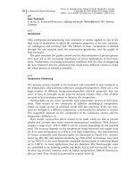
The most common sensors to be used in either industrial or research environ-
ments are force, power, and acoustic emission (AE) sensors [2]. Figure 4.4-1
shows the set-up for the most popular integration of sensor systems in either sur-
face or outer diameter grinding.
4.4 Abrasive Processes 237
Fig. 4.4-1 Possible positions of force, AE, and power sensors in grinding
4.4.3.1 Force Sensors
The first attempts to measure grinding forces go back to the early 1950s and were
based on strain gages. Although the system performed well to achieve substantial
data on grinding, the most important disadvantage of this approach was the sig-
nificant reduction in the total stiffness during grinding. Hence research was done
to develop alternative systems. With the introduction of piezoelectric quartz force
transducers, a satisfactory solution was found. In Figure 4.4-1, different locations
for these platforms in grinding are shown. In surface grinding most often the
platform is mounted on the machine table to carry the workpiece. In inner (ID)
or outer (OD) diameter grinding this solution is not available owing to the rota-
tion of the workpiece. In this case either the whole grinding spindle head is
mounted on a platform or the workpiece spindle head and sometimes also the
tailstock are put on a platform.
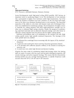
Figure 4.4-2 shows an example of a force measurement with the grinding spin-
dle head on a platform during ID plunge grinding. In this case the results are
used to investigate the influence of different coolant supply systems while grind-
ing case hardened steel. The force measurements make it clear that it is not possi-
ble to grind without coolant using the chosen grinding wheel owing to wheel
loading and high normal and tangential forces. However, it is also seen that there
is a high potential for minimum quantity lubrication (MQL) with very constant
force levels over the registered related material removal [3]. For OD grinding it is
also possible to use ring-type piezoelectric dynamometers. With each ring again
all three perpendicular force components can be measured; they are mounted un-
der preload behind the non-rotating center points. To complete possible mounting
positions of dynamometers in grinding machines, the dressing forces can also be
monitored by the use of piezoelectric dynamometers, eg, the spindle head of rotat-
ing dressers can be mounted on a platform. Besides these general solutions,
many special set-ups have been used for non-conventional grinding processes
4 Sensors for Process Monitoring238
Fig. 4.4-2 Grinding force measurement with platform dynamometer. Source: Brunner [3]
such as ID cut-off grinding of silicon wafers and ID grinding of long small bores
with rod-shaped tools.
As already stated for cutting, also for abrasive processes the application of dy-
namometers can be regarded as state of the art. The problems of high investment
and missing overload protection are also valid.
However, wire strain gages are also still in use. For example, the force measure-
ment in a face grinding process of inserts is not possible with a piezoelectric sys-
tem owing to limited space. In this case an integration of wire strain gages with a
telemetric wireless data exchange was successfully applied [4].
4.4.3.2 Power Measurement
As explained for cutting in Section 4.3.3.3, the measurement of power consump-
tion of a spindle drive can be regarded as technically simple. Also for abrasive pro-
cesses the evidence is definitely limited. The amount of power used for the
material removal process is always only a fraction of the total power consumption.
Nevertheless, power monitoring of the main spindle is widely used in industrial
applications by defining specific thresholds to avoid any overload of the whole ma-
chine tool due to bearing wear or any errors from operators or automatic han-
dling systems. However, there are also attempts to use the power signal of the
main spindle in combination with the power consumption of the workpiece spin-
dle to avoid grinding burn. This approach is further discussed in Section 3.3.
4.4.3.3 Acceleration Sensors
In Section 4.3.3 the difficulty of separating acceleration sensors from AE sensors
has already been mentioned. In abrasive processes the major application for accel-
eration sensors is related to balancing systems for grinding wheels. Especially
large grinding wheels without a metal core may have significant imbalance at the
circumference. With the aid of acceleration sensors the vibrations generated by
this imbalance are monitored during the rotation of the grinding wheel at cutting
speed. Different systems are in use to compensate this imbalance, eg, hydro com-
pensators using coolant to fill different chambers in the flange or mechanical bal-
ancing heads, which move small weights to specific positions. Although these sys-
tems are generally activated at the beginning of a shift, they are able to monitor
the change of the balance state during grinding and can continuously compensate
the imbalance.
4.4.3.4 Acoustic Emission Systems
Systems based on AE must be regarded as very attractive for abrasive processes.
An introduction to the AE technique and a brief explanation of the physical back-
ground is given in Section 3.3.3.4. Figure 4.4-1 shows the possible mounting posi-
tions for AE sensors on different components of a grinding machine. Either the
spindle drive units, the tool and grinding wheel, or the workpiece can be
4.4 Abrasive Processes 239
equipped with a sensor. In addition, fluid-coupled sensors are also in use without
any direct mechanical contact to one of the mentioned components. As pointed
out before, the time domain course of the root mean square value U
AE, RMS
is one
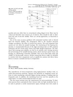
of the most important quantities for characterizing the process state. In Figure
4.4-3 as an example the correlation between the surface roughness of a ground
workpiece and the root mean square value of the AE signal is shown [5].
A three-step OD plunge grinding process with a conventional corundum grind-
ing wheel was monitored. It is obvious that for a dressing overlap of U
d
= 2 the
generated coarse grinding wheel topography is leading to a high initial surface
roughness of R
z
=5 lm. Owing to continuous wear of the grains, the roughness
even increases during the material removal. For the finer dressing overlap of
U
d
= 10 a smaller initial roughness with a significant increase can be seen for the
first parts followed by a decreasing tendency. This tendency of the surface rough-
ness is also represented by the AE signal. Higher dressing overlaps lead to more
cutting edges, thus resulting in a higher AE activity. The sensitivity of the fine
finishing AE signal is higher, because the final roughness is mainly determined
in this process step. Meyen [5] has shown in many other tests that monitoring of
the grinding process with AE is possible.
In recent years, research has been conducted on high-resolution measurement
of single cutting edges in grinding. The root mean square value must be regarded
as an average statistical quantity, usually often low-pass filtered and thus not
really suitable to reveal short transient effects such as single grit contacts. Webster
et al. observed burst-type AE signals of single grits in spark-in and spark-out
stages of different grinding operations by analyzing the raw AE signals with a spe-
cial high-speed massive storage data acquisition system [6].
In addition to these time-domain analyses, the AE signal can also be investi-
gated in the frequency domain. Different effects such as wear or chatter vibration
have different influences on the frequency spectrum, so it should be possible to
4 Sensors for Process Monitoring240
Fig. 4.4-3 Correlation between surface roughness and the AE r.m.s. signal. Source: Meyen [5]
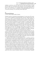
use the frequency analysis to separate these effects. Figure 4.4-4 shows the results
of a frequency analysis of the AE signal in OD plunge grinding with a vitreous
bond CBN grinding wheel [7]. As a special feature the AE-sensor is mounted the
grinding wheel core and transfers the signals via a slip ring to the evaluation com-
puter, so both grinding and dressing operations can be monitored. The results re-
veal that no significant peak can be seen after dressing and first grinding tests.
Only after a long grinding time do specific frequency components emerge from
the spectrum which show a constantly rising power during the continuation of
the test. The detected frequency is identical with the chatter frequency, which
could be determined by additional measurements. The AE-signals were used as
input data for a neural network to identify automatically the occurrence of any
chatter vibrations in grinding [7].
Owing to the general advantages of AE sensors and their variety, almost any
process with bond abrasives has already been investigated with the use of AE. Sur-
face grinding, ID and OD grinding, centerless grinding, flexible disk grinding,
gear profile grinding, ID cut-off grinding of silicon wafers, honing, and grinding
with bond abrasives on tape or film type substrates have all been subjects of AE
research.
4.4.3.5 Temperature Sensors
In any abrasive process, mechanical, thermal, and even chemical effects are usually
superimposed in the zone of contact. Grinding in any variation generates a signifi-
cant amount of heat, which may cause a deterioration of the dimensional accuracy of
the workpiece, an undesirable change in the surface integrity state, or increased
wear of the tool. In Section 3.3.3.3 some sensors for temperature measurement
have already been explained. Figure 4.4-5 shows the most popular temperature mea-
4.4 Abrasive Processes 241
Fig. 4.4-4 Acoustic emission frequency analysis for chatter detection in grinding. Source: Waku-
da et al. [7]
surement devices. The preferred method for temperature measurement in grinding
is the use of thermocouples. The second metal in a thermocouple can be the work-
piece material itself; this set-up is called the single-wire method.
A further distinction is made according to the type of insulation. Permanent in-
sulation of the thin wire or foil against the workpiece by use of sheet mica is
known as open circuit. The insulation is interrupted by the individual abrasive
grains, hence measurements can be repeated or process conditions varied until
the wire is worn or damaged. Many workers (eg, [8]) have used this set-up. Also
the grinding wheel can be equipped with the thin wire or a thermo foil, if the in-
sulation properties of abrasive and bond material are adequate. In the closed-cir-
cuit type, permanent contact of the thermal wire and the workpiece by welding or
brazing is achieved. The most important advantage of this method is the possibili-
ty of measuring temperatures at different distances from the zone of contact until
the thermocouple is finally exposed to the surface. For the single-wire method it
is necessary to calibrate the thermocouple for each different workpiece material.
This disadvantage is overcome by the use of standardized thermocouples, where
the two different materials are assembled in a ready-for-use system with sufficient
protection. A large variety of sizes and material combinations are available for a
wide range of technical purposes. With this two-wire method it is again possible
to measure the temperatures at different distances from the zone of contact. This
approach can be regarded as most popular for temperature measurement in
grinding. A special variation of this two-wire method is the use of thin-film ther-
mocouples [8, 9], (see also Section 3.3.3.3). The advantage of this method is an ex-
tremely small contact point to resolve temperatures in a very small area and the
possibility of measuring a temperature profile for every single test depending on
the number of evaporated thermocouples in simultaneous use.
4 Sensors for Process Monitoring242
Fig. 4.4-5 Temperature measurement systems in grinding
In Figure 4.4-6, temperature measurements during grinding of Al
2
O
3
ceramic
with a resin-bonded diamond grinding wheel using these thin-film thermocouples
are shown [9]. Obviously the setting quantities have a significant influence on the
generation of heat in the zone of contact. Especially the heat penetration time is
of major importance. In deep grinding with a very low tangential feed speed, high
temperatures are registered, whereas higher tangential feed speeds in pendulum
grinding lead to a significant temperature reduction. As expected, the avoidance
of coolant leads to higher temperatures compared with the use of mineral oil.
However, in any case for either single- or two-wire methods the major disad-
vantage is the great effort needed to carry out these measurements. Owing to the
necessity to install the thermocouple as close as possible to the zone of contact, it
is always a technique where either the grinding wheel or workpiece have to be
specially prepared. Hence all these methods are only used in fundamental re-
search; industrial use for monitoring is not possible owing to the partial destruc-
tion of major components.
In addition to these heat conduction-based methods, the second group of usable
techniques is related to heat radiation. Infrared radiation techniques have been
used to investigate the temperature of grinding wheel and chips. By the use of a
special infrared radiation pyrometer, with the radiation transmitted through an op-
tical fiber, it is even possible to measure the temperature of working grains of the
grinding wheel just after cutting [10]. Also the use of coolant was possible and
could be evaluated. In any case, these radiation-based systems need careful cali-
bration, taking into account the properties of the material to be investigated, the
optical fiber characteristics, and the sensitivity of the detector cell. However, again,
for most of the investigations preparation of the workpiece is necessary, as shown
in Figure 4.4-5 (bottom left).
4.4 Abrasive Processes 243
Fig. 4.4-6 Grinding temperature measurement with thin-film thermocouples. Source: Lierse [9]
The second heat radiation-based method is thermography. For this type of mea-
surement, the use of coolants is always a severe problem, because the initial radia-
tion generated in the zone of contact is significantly reduced in the mist or direct
flow of the coolant until it is detected in the camera. Thus the major application
of this technique was limited to dry machining. Brunner was able to use a high-
speed video thermography system for OD grinding of steel to investigate the po-
tential of dry or MQL grinding [3].
All the mentioned temperature sensors can also be distinguished with regard to
their measurement area. Video thermography is a technique to obtain average in-
formation about the conditions in the contact zone. For this reason it might be
called macroscopic temperature measurement. Pyrometers can either give average
information, but as Ueda and others have shown, single-grain measurements can
also be conducted depending on the diameter of the optical fibers. Concerning
the use of thermocouples, the situation is more difficult. Standard thermocouples
and the closed-circuit single-wire method are used to measure at a specific dis-
tance from the zone of contact. Thus the average temperature at this point can be
detected; the measurement spot might be extremely small, especially in the case
of evaporated thin-film thermocouples. This might be called microscopic tempera-
ture measurement, but single-grain contact detection is not possible. The open-cir-
cuit method with the thin thermal wire, which is exposed to the surface, is the
only real microscopic temperature measurement technique, because in this case
single grains generate the signal. However, the response time of this system is
significant, so it must be established critically whether all single contacts can be
registered.
4.4.4
Sensors for the Grinding Wheel
The grinding wheel state is of substantial importance for the achievable result.
The tool condition can be described by the characteristics of the grains. Wear can
lead to flattening, breakage, and even pullout of whole grains. Moreover, the num-
ber of cutting edges and the ratio of active to passive grains are of importance.
Also the bond of the grinding wheel is subject to wear.
Owing to its hardness and composition, it influences significantly the described
variations of the grains. In any case, wheel loading generates negative effects due
to insufficient chip removal and coolant supply. All these effects can be summarized
as grinding wheel topography, which changes during the tool life between two dres-
sing cycles. As a resulting effect, the size of the grinding wheel and its diameter are
reduced. In most cases dressing cycles have to be carried out without any informa-
tion about the actual wheel wear. Commonly, grinding wheels are dressed without
reaching their end of tool life in order to prevent workpiece damage, eg, workpiece
burn. Figure 4.4-7 gives an overview of different geometric quality features concern-
ing the tool life of grinding wheels. As a rule the different types of wheel wear are
divided into macroscopic and microscopic features. Many attempts have been made
to describe the surface topography of a grinding wheel and to correlate the quantities
4 Sensors for Process Monitoring244
with the result on the workpiece. All methods that need a stationary object in a lab-
oratory surrounding, which means that the grinding wheel is not rotating and even
dismounted, will not be discussed. Attention is focused on dynamic methods, which
are capable of being used in the grinding machine during the rotation of the tool. If
only the number of active cutting edges is of interest, some already introduced tech-
niques can be used. Either piezoelectric dynamometers or thermocouple methods
have been used to determine the number of active cutting edges.
In Figure 4.4-8 other methods are introduced that are suitable for dynamic mea-
surement of the grinding wheel. Most of the systems are not able to detect all mi-
cro- and macro-geometric quantities, and can only be used for special purposes.
4.4 Abrasive Processes 245
Fig. 4.4-7 Geometric quantities of a grinding wheel
Fig. 4.4-8 Sensors for grinding wheel topography measurement
4.4.4.1 Sensors for Macro-geometric Quantities
The majority of sensors are capable of measuring the macro-geometric features.
Any kind of mechanical contact of a sensor with the rotating tool causes serious
problems, because the abrasives always tend to grind the material of the touching
element. Only by realizing short touching pulses with small touching forces and
by using a very hard tip material such as tungsten carbide is it possible to achieve
satisfactory results. For instance, such a system with an eccentric drive to realize
the oscillation of the pin to measure the radial wheel wear at cutting speeds of up
to 35 m/s has been used [11]. However, coolant supply and corundum grinding
wheels with a porous vitreous bond caused severe problems. In any case, these
tactile-based methods on rotating tools are only suitable for macro-geometric mea-
surement and are limited to a few studies.
Another group of sensors for the measurement of grinding wheels is based on
pneumatic systems. Although this method is in principle also not able to detect
the micro-geometric features of a grinding wheel owing to the nozzle diameter of
1 mm or more, they are important for determining the macro-geometry. Systems
with compressed air supply and those without have to be distinguished. The latter
are characterized by measurement of the airflow around the rotating grinding
wheel. The results obtained reveal a dependence of the airflow on the distance of
the sensor from the surface, on the circumferential speed, and to a small extent
on the topography of the grinding wheel. The method with a compressed air sup-
ply is based on the nozzle-bounce plate principle, with the grinding wheel being
the bounce plate. These systems are capable of measuring the distance changes
and radial wear with a resolution of 0.2 lm. Especially this feature and the com-
paratively easy set-up and moderate costs are the main reasons why pneumatic
sensors have already found acceptance in industrial application.
Another possibility of registering the macro-geometry of a grinding wheel has
been reported [12]. In high-speed ID grinding with CBN wheels, a spindle with ac-
tive magnetic bearings (AMBs) was used to achieve the necessary circumferential
speed of 200 m/s with small-diameter wheels. These spindles have the opportunity
to shift the rotor from rotation around the geometric center axis to the main axis of
inertia to compensate any imbalance. Especially if electroplated CBN wheels are
used without the possibility of dressing, it is necessary to use balancing planes.
To measure the runout of these grinding wheels on the abrasive layer at very high
circumferential speeds, capacitive sensors have shown the best performance.
The AE signal can also be used to determine the macro-geometry of the grind-
ing wheel. In [13] a system was proposed consisting of a single-point diamond
dresser equipped with an AE sensor to detect exactly the position of the grinding
wheel surface. Because AE signals can be obtained without contact of the dresser
and the wheel due to turbulence, in total three different contact conditions can be
distinguished, non-contact, elastic contact, and brittle contact. It is proposed to
use the AE level of the elastic contact range to monitor the exact position of the
grinding wheel. The only disadvantage is the current limitation to a single-point
dresser. To overcome this demerit, an extension to rotating dressing tools is the
subject of current research [14].
4 Sensors for Process Monitoring246
Another principle used to determine radial wheel wear is based on a miniature
radar sensor [15]. The usual radar technique is known from speed and traffic con-
trol applications with a maximum accuracy in the centimeter range. The sensor
used for grinding works on an interferometric principle. With an emitting fre-
quency of 94 GHz and a wavelength of k =3.18 mm, this sensor has a measuring
range of 1 mm and a resolution of 1 lm. The main advantages are the robustness
against any dust, mist, or coolant particles and the possibility of measuring on
any solid surface. The sensor has been used in surface grinding of turbine blades
with continuous dressing (CD). A control loop was established to detect and con-
trol the radial wear of the grinding wheel taking into account the infeed of the
dressing wheel.
4.4.4.2 Sensors for Micro-geometric Quantities
In addition to these systems for macro-geometric features, other sensors are able
to give information about the micro-geometry. The loading of a grinding wheel
with conductive metallic particles as a special type of micro-geometric wear can be
detected by using sensors based on inductive phenomena. The sensor consists of
a high permeability core and a winding. It is positioned at a short distance from
the surface. The metallic particles generate a change in the impedance, which can
be further processed to determine the state of wheel loading. A conventional mag-
netic tape recorder head may also be used to detect the presence and relative size
of ferrous particles in the surface layer of a grinding wheel. As only this special
type of wear in grinding of metallic materials can be detected, these sensors have
not achieved practical application.
The mentioned limitations of all the so-far introduced techniques turn the at-
tention towards optical methods. These seem to be very promising because of
their frequency range and independence of the surface material. A scattered light
sensor was used to determine the reflected light from the grinding wheel surface
by using charge-coupled device (CCD) arrays. The first attempts at an optical-
based measurement of the topography at cutting speeds were reported in [16]. An
opto-electronic sensor with a fast Si photodiode as receiver and either a xenon va-
por lamp or halogen light source was used to measure the pulses of reflected
light on so-called wear flat areas. Tests have shown that the number of pulses
changes during grinding, hence a possible monitoring of the wear state was pro-
posed. However, hardware limitations, especially problems with the light sources,
did not lead to further success at that time. Gotou and Touge took up the same
principle again [17], keeping the Si photodiode as receiver but this time using a la-
ser source with 670 nm wavelength and a personal computer for control. Grind-
ing wheels in wet-type grinding at 30 m/s could be measured. Again, it was stat-
ed that the wear flat areas are registered by the output signal and that these areas
change during grinding.
The optical method with the highest technical level so far is based on laser tri-
angulation. The measurement principle and results of micro-geometric character-
ization of the grinding wheel surface to determine surface integrity changes are
4.4 Abrasive Processes 247
given in Section 3.3.4. In the following, results of macro-geometric measurements
will be presented.
As mentioned, no practical limitations exist for the determination of macro-geo-
metric quantities such as radial runout, and the maximum surface speed may
even exceed 300 m/s [18]. Figure 4.4-9 shows the result of an investigation of OD
plunge grinding of ball-bearing steel with a corundum grinding wheel. Using
three different material removal rates, the change of the radial runout as a func-
tion of the material removal at 30 m/s was plotted. For the smallest material re-
moval rate no change is detectable from the initial value after dressing. However,
for increasing material removal rates of Q '
w
= 1.0 and 2.0 mm
3
/mm s the radial
runout rises after a specific material removal. In the latter cases the increasing ra-
dial runout leads to chatter vibrations with visible marks on the workpiece sur-
face. Obviously the system is capable of detecting significant macro-geometric
changes due to wear of the grinding wheel. The limitations of the system regard-
ing the micro-geometric characterization have been discussed in Section 3.3.4.
The examples presented of grinding wheel sensors reveal that the majority of
systems are related to macro-geometric features. However, many attempts have
been made to establish especially optical systems for the measurement of micro-
geometric quantities. The overall limitation for these techniques will always be
the rough conditions in the working space of a grinding machine with coolant
and process residues in the direct contact with the object to be measured. In
many cases it is therefore preferable to measure directly the manufactured work-
piece itself.
4 Sensors for Process Monitoring248
Fig. 4.4-9 Optical macro-geometric grinding wheel topography measurement
4.4.5
Workpiece Sensors
Two essential quality aspects determine the result of an abrasive process on the
workpiece. On the one hand the geometric quality demands have to be fulfilled.
These are dimension, shape, and waviness as essential macro-geometric quanti-
ties. The roughness condition is the main micro-geometric quantity. However, in-
creasing attention is also paid to the surface integrity state of a ground workpiece
owing to its significant influence on the functional behavior. The physical proper-
ties are characterized by the change in hardness and residual stresses on the sur-
face and in sub-surface layers, by changes in the structure, and the likely occur-
rence of cracks (see Section 3.3). All geometric quantities can be determined by
using laboratory reference measuring devices. For macro-geometric properties any
kind of contact system can be used, eg, 3D coordinate measuring machines, con-
tour stylus instruments, or gages. Roughness measurement is usually performed
with stylus instruments giving standardized values, but optical systems are also
applied in some cases. Methods to determine physical quality characteristics are
mentioned in Section 3.3.
4.4.5.1 Contact-based Workpiece Sensors for Macro-geometry
The determination of macro-geometric properties of workpieces during manufac-
ture is the most common application of sensors in abrasive processes, especially
grinding. For decades contact sensors have been in use to determine the dimen-
sional changes of workpieces during manufacturing. A wide variety of in-process
gages for all kinds of operation are available. In ID or OD grinding the measur-
ing systems can either be comparator or absolute measuring heads, with the cap-
ability of automatic adjustment to different part diameters. The contact tips are
usually made of tungsten carbide, combining the advantages of wear resistance,
moderate costs, and adequate frictional behavior. The repeatability is in the region
of 0.1 lm [19]. Internal diameters can be gaged starting from 3 mm. If constant ac-
cess to the dimension of interest during grinding is possible, these gages are often
used as signal sources for adaptive control (AC) systems (see also Section 4.4-8). The
conventional technique for measuring round parts rotating around their rotational
axis can be regarded state of the art. The majority of automatically operating
grinding machines are equipped with these systems. In the survey of contact sen-
sors for workpiece macro-geometry in Figure 4.4-10 (top left), a more complex
measurement set-up is shown. Owing to the development of new drives and con-
trol systems for grinding machines, continuous path-controlled grinding of crank-
shafts has now become possible [20]. The crankshaft is clamped only once in the
main axis of the journals. For machining the pins the grinding wheel moves back
and forth during rotation of the crankshaft around the main axis to generate a cy-
lindrical surface on the pin. An in-process measurement device for the pin diame-
ter has to follow this movement. A first prototype system was installed in a crank-
shaft grinding machine. The gage is mounted on the grinding wheel head and
4.4 Abrasive Processes 249
moves back and forth together with the grinding wheel. A swivel joint effects the
height balancing. The same problem of measurement during eccentric movement
of a crankshaft pin occurs in the micro-finishing process (Figure 4.4-10, bottom
left). This last process in the production chain using single-layer abrasives bond
to a thin plastic belt is applied to give the pins and journals the desired final mi-
cro-geometry concerning roughness, bearing ratio, and crowning. The abrasive
film is automatically indexed before each cycle and pressed by hard, non-resilient,
and exactly formed shoes to the workpiece surface at specific controlled pressure.
The crankshaft rotates and oscillates for a specific cycle and drags single arms
with shoes, belt supply, and measuring gage for each pin and journal at the same
time. Size control is realized by a moving gage with contacting pins, which allow
stopping of the micro-finishing process on each bearing individually, when the fi-
nal dimension is reached. A machine tool with this in-process moving size con-
trol sensor system is already available.
The detection of waviness on the circumference of rotating symmetrical parts
during grinding is more complex owing to the demand for a significantly higher
scanning frequency. Foth has developed a system with three contacting pins at
non-constant distances to detect the development of waviness on workpieces dur-
ing grinding as a result of, eg, regenerative chatter [19] (Figure 4.4-10, top right).
Only by using this set-up was it possible to identify the real workpiece shape, tak-
ing into account the vibration of the workpiece center during rotation. The signal
of the waviness sensor was fed back to the control unit of the machine tool. If in-
creasing waviness was determined during grinding, the speed ratio between the
rotating grinding wheel and workpiece was changed to suppress regenerative ef-
fects. Although the system performance was satisfactory and could meet all indus-
trial demands concerning robustness, it was only used to confirm theoretical sim-
ulations. The knowledge gained can be directly applied to grinding machine con-
trols to avoid regenerative chatter, hence waviness sensors are not really needed.
4 Sensors for Process Monitoring250
Fig. 4.4-10 Contact sensor systems for workpiece macro-geometry
The last example of contact-based macro-geometric measurement in a machine
tool is related to gear grinding (Figure 4.4-10, bottom right). Especially for manu-
facturing of small bath sizes or single components of high value, it is essential to
fulfil the ‘first part good part’ philosophy. For these reasons several gear grinding
machine tool builders have decided to integrate an intelligent measuring head in
their machines to be able to measure the characteristic quantities of a gear, eg,
flank modification, pitch, or root fillet. Usually a measurement is done after
rough grinding, before the grinding wheel is changed or redressed for the finish
operation. Sometimes also the initial state before grinding is checked to compen-
sate for large deviations resulting from distortions due to heat treatment. Of
course, the measurement can only be done if the manufacturing process is inter-
rupted. However, the main advantage is still a significant saving of time. Any re-
moval of the part from the grinding machine tool for checking on an additional
gear measuring machine will take a longer time. Also the problem of precision
losses due to rechucking is not valid, because the workpiece is rough machined,
measured, and finished in the same set-up. These arguments are generally true
for any kind of high-value parts with small bath sizes and complex grinding op-
erations. Hence it is not surprising that also in the field of aircraft engine manu-
facturing new radial grinding machines are equipped with the same kind of touch
probe system in the working space. Geometric quality data are acquired on the
machine tool before the next grinding operation in the same chuck position is
started [21]. Nevertheless, the use of a measuring head in a complex gear or tur-
bine blade grinding machine is not a pure sensor application. The measurement
is only possible in auxiliary process time, but between succeeding process steps. It
must be stated as a borderline case, but should be included because of the high
technical level and industrial relevance.
4.4.5.2 Contact-based Workpiece Sensors for Micro-geometry
The determination of micro-geometric quantities on a moving workpiece by using
contact sensor systems is a challenging task. Permanent contact of any stylus with
the surface is not possible, because the dynamic demands are much too high.
Only intermittent contacts can be used to generate a signal, which should be pro-
portional to the roughness. Saljé has introduced a sensor based on a damped
mass spring element [22]. The surface of the fast-moving workpiece stimulates
self-oscillations of the sensing element, which are correlated with the roughness.
The system was improved and modified in the following years, and a set-up
with parallel springs was successfully applied to the honing process [23], (Figure
4.4-11). The sensor was integrated in the honing tool and the pre-amplified signal
was transmitted to the evaluation unit via slip ring contact. Figure 4.4-11 shows
the result of the calibration of this sensor system with conventional stylus rough-
ness measurements. A linear correlation in the range of interest of R
z
= 2–20 lm
was found.
Rotating roughness sensors for OD grinding have also been tested, but differ-
ent limitations concerning diameter and width of the workpiece did not allow
4.4 Abrasive Processes 251
practical application. A second important problem is related to the measuring di-
rection of these in-process sensors. Whether the sensor was combined with the
tool in the case of honing or fed towards the workpiece by auxiliary systems, the
measuring direction was always in the direction of the abrasive process. Any sty-
lus-type reference measurement is usually done perpendicular to the grinding or
honing direction. In the parallel direction the diamond tip is likely to stay in just
one groove and then suddenly jump out to the next one. Hence a parallel mea-
surement does not give substantial information on the roughness state and is
usually avoided. Although attempts have been made with additional axial feed of
the sensor to generate a scroll-type movement on the surface [22], the idea of con-
tacting the surface for roughness measurement did not lead to industrial success.
4.4.5.3 Contact-based Workpiece Sensors for Surface Integrity
The range of contact sensors on workpieces is completed with systems related to
surface integrity measurement. A description of the available techniques is given
in Section 3.3.5.
4.4.5.4 Non-contact-based Workpiece Sensors
All the mentioned restrictions of contact sensor systems on the workpiece surface
gave a significant push to develop non-contact sensors. As for grinding wheels,
again optical systems seem to have a high potential. In Figure 4.4-12 different opti-
cal systems and two other non-contacting sensor principles are introduced.
As a very fast optical system for measuring macro-geometric quantities, a laser-
scanner is shown. The scanner transmitter contains primarily the beam-emitting
He-Ne laser, a rotating polygonal mirror and a collimating lens for paralleling the
diffused laser beam. The set-up of the scanner receiver contains a collective lens
and a photodiode. The electronic evaluation unit counts the time when the photo-
4 Sensors for Process Monitoring252
Fig. 4.4-11 Contact workpiece roughness sensor for ID honing. Source: von See [22]
diode is covered by the shadow of the object. The diameter is a function of the
speed of the polygonal mirror and the time during which the laser beam does not
reach the covered photodiode. Conicity can be evaluated by an axial shifting of the
workpiece. In principle this optical measurement cannot be performed during the
application of coolant. During grinding the system can be protected by air bar-
riers and mechanical shutters. Laser-scanners were first installed in grinding ma-
chines to measure the thermal displacement of machine tool components or to
determine the profile accuracy of the dressed grinding wheel. For a detailed work-
piece characterization, a set-up with a laser-scanner outside of the working space
of the grinding machine was preferred. In [24] the layout and realization of a flex-
ible measurement cell incorporating a laser-scanner for the determination of
macro-geometric properties was introduced. The system is able to measure auto-
matically the desired quantities within the grinding time, and the information can
be fed back to the grinding machine control unit.
For the determination of macro- and micro-geometric quantities a different opti-
cal system has to be applied. The basis of a scattered light sensor for the measure-
ment of both roughness and waviness is the angular deflection of nearly normal
incident rays. The set-up of a scattered light sensor is shown in Figure 4.4-12
(bottom left). A beam-splitting mirror guides the reflected light to an array of
diodes. This array is able to record the distribution only in one optical flat. The
alignment of the sensor is therefore of essential importance. To obtain informa-
tion about the circumferential waviness and roughness, the array has to be per-
pendicular to the rotation axis of the workpiece. The transverse roughness accord-
ing to the stylus testing is measurable with a 908 rotation of the sensor. A com-
mercially available system was introduced in the 1980s [25] and used in a wide
range of tests. The optical roughness measurement quantity of this system is
4.4 Abrasive Processes 253
Fig. 4.4-12 Non-contact sensor systems for workpiece quality characterization
called the scattering value, S
N
, and is deduced from the intensity distribution. In
different tests the scattered light sensor was directly mounted in the working
space of the grinding machine to measure the workpiece roughness [26]. A com-
pressed air barrier protected the optical system. In all investigations it was tried to
establish a correlation between optical and stylus roughness measurements. It is
possible to obtain such a close relationship while grinding or honing with con-
stant process parameters [23, 26, 27] (Figure 4.4-13). This restriction is indispens-
able, because a change of input variables such as dressing conditions or tool speci-
fication may lead to workpieces with the same stylus roughness values R
a
or R
z
but different optical scattering values S
N
. If a quantitative roughness characteriza-
tion referring to stylus values is demanded, a time-consuming calibration will be
always necessary. As shown in Figure 4.4-13, the measuring direction also has to
be clearly defined to achieve the desired correlation. A second limitation is seen
in the sensitivity of the system. The scattered light sensor is able to determine dif-
ferences in high-quality surfaces, but for roughness states of ten-point height
R
z
> 5.0 lm the scattering value S
N
reaches its saturation with decreasing accuracy
already starting at R
z
= 3.0 lm [23]. Hence some relevant grinding or honing op-
erations cannot be supervised by this sensor system.
In addition to the installation in the grinding machine, such a scattered light
sensor was also integrated in the mentioned flexible measurement cell [24]. This
set-up of optical systems outside the grinding machine but integrated in the
close-to-machine control loop seems to be superior to the tests under coolant sup-
ply in the grinding machine. After all the mentioned investigations, no industrial
application of a scattered light sensor in the working space of a grinding machine
tool has been reported.
A different optical sensor is based on a laser diode [28] (Figure 4.4-12, top mid-
dle). The sensor is equipped with a gallium arsenide diode, which is commonly
used in a CD player. With a lens system the beam is focused on the surface and
4 Sensors for Process Monitoring254
Fig. 4.4-13 Different correlation curves for an optical scattered light sensor. Source: König und
Klumpen [27], von See [23], present authors
the reflected light is registered on an array of four photodiodes. This system can
be used as an autofocus system, with the signal from the four diodes, the focus
lens is moved until the best position for minimum diameter is reached. The cor-
relation of the obtained optical average roughness R
a, opt
with the stylus reference
measurement is shown in Figure 4.4-14 (left). An almost linear dependence of the
two different roughness quantities could be found. However, the system is much
too slow to be used for any in-process measurement. By using the focus-error sig-
nal of the four diodes without moving the lens, it is possible to increase the mea-
surement speed significantly. Another optical approach for in-process roughness
measurement is based on the use of optical fiber sensors [29]. The workpiece sur-
face is illuminated through fiber optics and the intensity of the reflected light is
detected and evaluated (Figure 4.4-12, middle bottom).
The latter set-up was chosen to increase the sensitivity of the sensor system. The
photo-sensor in the normal direction will register less intensity, whereas the inclined
photo-sensor will detect more intensity with larger light scattering due to increased
roughness. The ratio of the two photo-sensors is related to roughness changes (Fig-
ure 4.4-14, middle). A second advantage of the set-up with two fiber optics despite
the increased sensitivity is the achieved independence of the workpiece material.
Coolant flows around the whole sensor head to make measurement possible during
grinding. It is essential to keep the coolant as clean as possible during operation,
because the reflection conditions are definitely influenced by the filtering state of
the fluid. This is the major drawback of the sensor system, because the coolant qual-
ity is not likely to be stable in production. In addition to these mentioned systems,
some other optical techniques for on-line measurement of surface topography have
been proposed, eg, speckle patterns. Although the measurement speed may allow
the installation of these systems in a production line operation, their use as sensors
in the machine tool working space is not realistic.
4.4 Abrasive Processes 255
Fig. 4.4-14 Correlation curves for different workpiece roughness sensors. Source: Westkämper
[28], present authors
In summary, owing to all the problems related to coolant supply, it must be
stated that these conditions do not allow the use of optical systems during grind-
ing or honing as reliable and robust industrial sensors. Only optical sensor appli-
cations measuring with interruptions of coolant supply either in the working
space of the machine tool or in the direct surrounding have gained importance in
industrial production.
In addition to optical sensors, two other principles are also used for non-contact
workpiece characterization. A pneumatic sensor as shown in Figure 4.4-12 (top
right) was designed and used for the measurement of honed cylinders [30]. The
measurement is based on the already mentioned nozzle-bounce plate principle. A
correlation with stylus measurements is possible (Figure 4.4-14, right). The main
advantages of this system are the small size, the robustness against impurities
and coolant, and the fact that an area and not a trace is evaluated. Hence in prin-
ciple no movement of the sensor during measurement is necessary.
The last system to be introduced as a non-contact workpiece sensor is based on
an inductive sensor. The sensor is used in gear grinding machines to identify the
exact position of tooth and tooth slot at the circumference of the pre-machined
and usually heat-treated gear (Figure 4.4-12, bottom right). The gear rotates at
high speed and the signal obtained is evaluated in the control unit of the grinding
machine. This signal is used to index the gear in relation to the grinding wheel to
define the precise position to start grinding and to avoid any damage to a single
tooth. It is also possible to detect errors in tooth spacing. Gears with unacceptable
distortions after heat treatment can be identified and rejected to avoid overload of
the grinding wheel, especially when using CBN as abrasive.
4.4.6
Sensors for Peripheral Systems
Primary motion between the tool and workpiece characterizes the grinding pro-
cess, but as already stated at the beginning of Section 4.4 also supporting pro-
cesses and systems are of major importance. In this section basically the monitor-
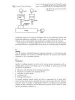
ing of the conditioning process and the coolant supply will be discussed.
4.4.6.1 Sensors for Monitoring of the Conditioning Process
The condition of the tool i.e. the grinding wheel is a very decisive factor for the
achievable result during the process. Hence the grinding wheel has to be pre-
pared for the desired purpose by using a suitable conditioning technology. The
major problem in any conditioning operation is the possible difference between
nominal and real conditioning infeed. There are four main reasons for these de-
viations. The unknown radial grinding wheel wear after removal of a specific
workpiece material volume must be regarded as a significant factor. Also the
changing relative position of grinding wheel and conditioning tool due to thermal
expansion of machine components is relevant. As a third reason, infeed errors re-
lated to friction of the guide-ways or control accuracy have to be considered,
4 Sensors for Process Monitoring256
although their influence is declining in modern grinding machines. The last rea-
son to mention is the wear of the conditioning tool, which of course depends on
the individual type. Especially for rotating dressers only after regular use for sev-
eral weeks can the first wear effects be registered.
Owing to the great importance of the grinding wheel topography, the monitor-
ing of the conditioning operation has been the subject for research for decades.
Already in the early 1980s it was first tried to use an AE-based system for the
monitoring of the dressing operation [31]. At that time the work was concentrated
on the dressing of conventional grinding wheels with a static single-point dia-
mond dresser. The AE sensor was mounted on the dresser and connected to an
evaluation unit. It was possible to detect first contact of the dresser and the grind-
ing wheel and the AE intensity could be used to determine the real dressing in-
feed as a function of dressing feed rate and grinding wheel speed. The dressing
feed speed could also be identified by the AE signal [32]. In addition, it was stated
that the AE signal reacts significantly faster to the first contact of dressing tool
and grinding wheel compared with the monitoring of the spindle power. Further
improvements also allowed information to be obtained about the actual profile of
the single-point diamond dresser. The limitation to straight cylindrical profiles
was overcome by Meyen, who developed a system capable of detecting dressing er-
rors on any complex grinding wheel profile [5] (Figure 4.4-15).
The strategy comprises the determination of a sliding average value with static
and dynamic thresholds for every single dressing stroke. The different geometry
elements are identified and the currently measured AE signal is compared with
the reference curve, which has to be defined in advance. With the calculation of
further statistical quantities such as standard deviation or mean signal inclination,
it is possible to identify the typical dressing errors in the case of the thresholds
being exceeded.
4.4 Abrasive Processes 257
Fig. 4.4-15 Dressing diagnosis for random grinding wheel profiles with AE signals. Source:
Meyen [5]
As a consequent next step, AE systems were tested for conditioning operations
of superabrasives such as CBN (eg, [7, 33]). The high hardness and wear resis-
tance of these grinding wheels require a different conditioning strategy and moni-
toring accuracy compared with conventional abrasives. The conditioning intervals
due to the superior wear resistance can amount to several hours. The dressing in-
feed should be limited to a range between 0.5 and 5 lm instead between 20 and
100 lm for conventional wheels in order to save wheel costs. Especially for vitre-
ous bonded CBN grinding wheels it was proposed to use very small dressing in-
feeds more frequently in order to avoid additional sharpening. This strategy,
known as ‘touch dressing’, revealed the strong demand to establish a reliable con-
tact detection and monitoring system for dressing of superabrasives. In most
cases rotating dressing tools are used. The schematic set-up of a conditioning sys-
tem with a rotary cup wheel, which is often used on internal grinding machines,
is shown in Figure 4.4-16.
The conditioning cycle consists of four stages: fast approach, contact detection,
defined infeed, and new initiation. The setting parameters such as number of
strokes, dressing infeed, and dressing feed rate are stored in the control unit of
the grinding machine. The fast approach is done with the NC axis of the ma-
chine. The dressing tool is moved to the last-stored dressing position with an ad-
ditional safety distance of, eg, 20 lm to avoid any undesired contact. Then the
dressing sub-program is started with the chosen infeed and feed rate of the dress-
ing tool for each stroke. In this state, a reference signal for the chosen contact de-
tection system can be recorded. In addition to AE techniques, other methods have
also been tested. Heuer additionally investigated the possibility of using either the
required power of the dressing tool spindle or a piezoelectric force measurement
for monitoring [33]. The latter technique was possible, because a piezoelectric ac-
tuator was installed as a high-precision positioning system for the infeed of the
dressing tool. With this additional equipment infeed extents of 0.25 lm could be
4 Sensors for Process Monitoring258
Fig. 4.4-16 Dressing monitoring with rotating diamond tools. Source: Heuer [33]
realized. Hence this system may also upgrade older machine tools with less accu-
racy. However, in any modern machine tool the in-built x-axis provides the infeed.
A further technique for contact detection was introduced in [34]. The measure-
ment of the rotational speed change of the high-frequency dressing spindle,
which gives a maximum number of revolutions of 60 000 min
–1
, was used to de-
termine not only the first contact, but also the whole dressing process. After con-
tact detection of any of the mentioned systems, the conditioning program is con-
tinued until the desired number of strokes and infeed are reached. Depending on
the type of system it is possible to monitor the course of the signal on the whole
width of the grinding wheel. Thus uneven macro-geometric wear of the wheel can
be registered, if the measured signal does not exceed the defined threshold refer-
ence level over the whole width. This strategy also assures a perfect macro-geo-
metric shape after conditioning. After finishing the conditioning process the final
position of the machine x-axis is stored to initialize the next operation.
The use of AE sensors for contact detection of the conditioning and dressing
operation can be regarded as state of the art. Many different systems are available.
New grinding machine tools with self-rotating conditioning tools are usually
equipped with an AE system already in the delivery state. Also the system with
dressing spindle rotational speed monitoring has found acceptance in industry,
because this system is regarded as very robust and is not influenced by coolant
supply or bearing noise, which is still regarded as the major limitation for all AE
systems. However, the importance of this last method is declining, because in
modern machine tools the control loops for the main drives are extremely fast
and thus a deviation in rotational speed is no longer a suitable signal source.
Hence the monitoring of the electrical power consumption of the dressing spindle
is becoming more attractive, because it has also reached sufficient sensitivity and
is installable with the least effort.
4.4.6.2 Sensors for Coolant Supply Monitoring
Relatively large contact areas characterize abrasive processes and especially grind-
ing operations. The large number of cutting edges generates a considerable
amount of heat in the zone of contact. Hence the reduction of friction and cool-
ing of the interacting parts is often necessary to avoid thermal damage. Therefore,
in almost all cases coolants are used to reduce heat and to provide sufficient lubri-
cation. These are the main functions of any coolant supply. Furthermore, the re-
moval of chips and process residues from the workspace of the machine tool, the
protection of surfaces, and human compatibility should be provided. Modern cool-
ant compositions also try to fulfil the contradictory demands of long-term stability
and biological recyclability.
At least with the wider use of superabrasives such as CBN, the possibility of high-
speed grinding, and highly efficient deep grinding, a closer view on the coolant sup-
ply began. Coolant pressure and flow rate measured with a simple flowmeter in the
coolant supply tube before the nozzle are now often part of the parameter descrip-
tions. Different authors have also worked on the influence of different nozzle de-
4.4 Abrasive Processes 259
signs (eg, [33]). In most cases the influence of different supply options such as con-
ventional flooding nozzles, shoe, spot jet, or spray nozzles, or even internal supply
through the grinding wheel, is described by using the already-mentioned process
quantities such as forces or temperature [35]. However, in addition to the technolo-
gical demands, environmental aspects of manufacturing have also attracted signifi-
cantly more attention. Especially the last mentioned point has led to a detailed inves-
tigation of coolant supply and the possibility of reducing or avoiding coolants in
grinding completely [36]. Heinzel and co-workers made a very systematic approach
to investigate the coolant-related influences and to optimize the relevant parameters
and designs. For the development of a suitable shoe nozzle design a special flow
visualization technique was used (Figure 4.4-17) [35, 37].
Tracer particles with almost the same density are added to the transparent fluid.
All parts of the nozzle of interest are made from acrylic glass and a CCD camera
records the flow images perpendicular to the light sheet plane. Although only a
qualitative result is available, this technique offers the possibility of systematically
studying and improving the whole design of coolant nozzles. As an example, in
Figure 4.4-17 (right) the flow behavior of a nozzle with straight guiding elements
at two different flow rates is shown. The coolant is mineral oil and the grinding
wheel is rotating at a speed of 100 m/s. For the lower flow rate of 10 L/min inho-
mogeneous flow behavior can be observed. Turbulences, backflow, and foam be-
tween top and center guiding elements and at the entry side of the grinding
wheel are visible. A doubling of the flow rate leads to steady flow behavior. In [35]
it is explained in detail that different flow rates need different adapted guiding
elements to achieve the best result.
In addition to this use of an optical monitoring method to optimize the design of
coolant nozzles, a special sensor installation for pressure and force investigations
was also introduced [35]. The force measurement is done by an already-discussed
4 Sensors for Process Monitoring260
Fig. 4.4-17 Flow behavior monitoring by means of particle image velocimetry. Source: Brinksmei-
er et al. [37]