Advances in Vehicular Networking Technologies Part 8 pptx
Bạn đang xem bản rút gọn của tài liệu. Xem và tải ngay bản đầy đủ của tài liệu tại đây (1.37 MB, 30 trang )
Advances in Vehicular Networking Technologies
202
There are two different approaches of secondary use of spectrum in cognitive radio context.
One is in the form of overlay, opportunistic usage of idle bands in the primary user’s (PU)
spectrum by cognitive radios and another in the form of underlay, using Ultra Wide Band
(UWB) technology ([cabric06]).
The rules in secondary use of frequency spectrum specify that licensed users, known as
Primary Users (PUs), have the rights for interference-free communication in certain bands.
When these bands are not used by the primary users, they can be used by Secondary Users
(SUs). As soon as a primary user starts activity in its channel, the SU has to vacate the
channel to avoid interference ([timmers07]). However, a cognitive radio (using a half duplex
transceiver) cannot scan the spectrum and transmit simultaneously in the same frequency
band. Then, for the protection of primary users, a maximum detection or sensing time must
be established. This detection time represents the maximum time of interference, from
secondary users, that a primary user can tolerate ([jia07]).
2.2 Rendezvous in multi-channel protocols
In multi-channel MAC protocols, Mobile Stations (MSs) exchange control information to
concur on the channel for data transmission in the user plane. Proposed protocols vary in
how MSs negotiate the channel to be used for data transmission and the way to solve
medium contention; these protocols can be divided according to their principle of
operation.
In single rendezvous protocols, the rendezvous between a sender and its receiver can take
place on at most one channel at any time, while in Multiple Rendezvous protocols, several
rendezvous can take place in different channels simultaneously, thereby mitigating the
control channel congestion ([mo07]).
In single rendezvous, three different classes of protocols can be distinguished based on the
mechanism of channel negotiation ([sheung07]). The Dedicated Control Channel approach,
which uses two transceivers (TRx), operates with a single channel only for control packets
exchange. In this approach, the MSs always tune one TRx to the control channel to make
agreements and be aware of neighbours’ negotiations. The other TRx is able to switch
channels and is used for data transmission. The Split Phase protocol uses only one TRx for
control and data packets. In this protocol, time is split into fixed periods of control and data
phases. The control phase is used as common control channel to make rendezvous, when
control phase ends, MSs switch to their selected channels and begin data transmission. The
third class of protocol is named Common Hopping, which also has only one TRx for both
control and data packets, in this protocol there is no CCCH. MSs hop synchronously
through all available channels and pauses hopping when sender and receiver agree on data
transmission using their current channel.
2.3 Hidden terminal problem in a single channel environment
Hidden terminal problem occurs when mobile stations cannot detect signal from other MSs
by carrier sensing because they do not have a physical connection to each other. Figure 2
illustrates this problem: MS “A” sends a message to MS “B”; “C” cannot detect the signal
from “A” since “C” is out of range of “A”. For station “C”, the channel is idle. When MS
“C” sends a message to “B”, this message will collide at “B” with the message sent from
“A”. In this scenario “C” is the hidden node to “A”.
An Overview of DSA via Multi-Channel MAC Protocols
203
Fig. 2. Hidden terminal problem in a single channel environment
2.4 Virtual carrier sensing using RTS/CTS exchange
To deal with the above problem, the IEEE 802.11 MAC layer uses the Distributed
Coordination Function (DCF) mechanism, which employs virtual carrier sensing to solve the
hidden terminal problem by using the RTS/CTS mechanism.
In this mechanism, when a mobile station wants to initiate communication, it first sends a
RTS (Request-To-Send) message and the receiver replies by sending a CTS (Clear-To-Send).
The RTS and the CTS contains the NAV (Network Allocation Vector), which is the expected
duration of time that other mobile stations, around the communication pair, must refrain
from sending data to avoid collisions.
This procedure can solve the hidden terminal problem in a single channel environment,
under the assumption that all mobile stations have the same transmission range. However,
the DCF mechanism cannot work well in a multi-channel environment, the reason is
because MSs may be transmitting or receiving data packets in different channels, missing
the RTS/CTS procedure of the DCF mechanism.
2.5 Multi-channel hidden terminal problem
This problem occurs when mobile stations in the network listen to different channels
missing the RTS/CTS procedure.
The Multi-Channel Hidden Terminal Problem is illustrated in figure 3. Initially, mobile
station “A” wants to communicate with “B”, then “A” sends an A-RTS to “B” on the
Common Control Channel (Channel 1). After receiving the A-RTS, MS B selects the Channel
2 to communicate with “A” and sends back an A-CTS, notifying their neighbours that the
data channel number 2 has been selected. In a single channel environment the RTS/CTS
exchange avoids collisions in the transmission ranges of “A” and “B”. However, in multi-
channel environments other mobile stations could be involved in communication in
different channels when the RTS/CTS procedure took place. That is the case of mobile
stations “C” and “D”, as they were communicating in channel 3 they did not hear the A-CTS
sent by “B”. When they finish their communication on Channel 3, mobile stations “C” and
“D” switch to Channel 1 and now they select Channel 2 to reinitiate communication. When
MS “C” sends the first message to “D”, this message will cause collision to mobile station
“A” and “B” on Channel 2.
Advances in Vehicular Networking Technologies
204
Fig. 3. Hidden terminal problem in Multi-channel protocols (figure inspired from Jungmin
So et al. [so04])
One possible solution would be a unique channel or moment in which every MS in the
network listens to, thereby, ensuring that the RTS/CTS procedure can be heard by all the
MSs, thus avoiding the Multi-Channel Hidden Terminal Problem ([so04]).
3. Multi-channel MAC protocols
3.1 “Comparison of multi channel MAC protocols” [mo07]
[mo07] presents a performance comparison between different multi-channel MAC
protocols, single rendezvous protocols (dedicated control channel, common hopping and
split phase) and multi rendezvous (parallel rendezvous).
Dedicated Control Channel Approach: This protocol uses 2 TRx per Mobile Station (MS),
one is used for control information exchange and the other is able to switch between
channels for data transmission. There is no need for synchronization to make rendezvous
because the control channel is always tuned by all the MSs in the network. However, this
protocol presents two principal problems, the need for 2 TRx and the possibility of control
channel bottleneck.
An Overview of DSA via Multi-Channel MAC Protocols
205
Fig. 4. Dedicated Control Channel Approach (figure inspired from [mo07])
Common Hopping Approach: This protocol uses 1 TRx per Mobile Station (MS); this TRx
is able to switch between channels for control information exchange and data
transmission. To make rendezvous, MSs hop synchronously over all the channels and
pauses its hopping sequence when the agreement between sender and receiver is made.
This protocol uses all the channels for data transmission. However, the synchronization
among MSs is crucial.
Fig. 5. Common Hopping Approach (figure inspired from [mo07])
Split Phase Approach: This protocol uses 1 TRx per Mobile Station (MS), time is divided
into control Phase and Data phase, this division has the objective to ensure that all MSs
listen to the control phase, thus avoiding the Multi-Channel Hidden Terminal problem
(MCHTP). Two important disadvantages of this protocol are the need for global
synchronization and the wasted data channels during the control phase. However, with
only one TRx, this protocol solves the MCHTP.
Fig. 6. Split Phase Approach (figure inspired from [mo07])
3.2 “McMAC: A parallel rendezvous multi-channel MAC protocol” [sheung07]
McMAC protocol uses 1 TRx per Mobile Station (MS). At the beginning, a sender chooses a
hopping pattern in a pseudo-random way using a seed to generate it, neighbours learn its
hopping sequence because is included in all the sender’s packets. To make rendezvous, a
MS can deviate from its default hopping sequence and hops to the receiver’s channel. In this
protocol multiples rendezvous can be made in different channels at the same time, thus
Advances in Vehicular Networking Technologies
206
improving the network throughput and avoiding control channel bottleneck. However, the
synchronization and coordination between MSs are essential.
Fig. 7. McMAC protocol (figure inspired from [mo07])
3.3 “SSCH: Slotted Seeded Channel Hopping for capacity improvement in IEEE 802.11
ad-hoc wireless networks” [bahl04]
SSCH protocol uses 1 TRx per Mobile Station (MS). In this protocol, each sender chooses one
of the possible hopping patterns generated in a pseudo-random way (one hopping pattern
for each available channel). To make rendezvous, a sender must wait until its current
hopping pattern intersects with that of the receiver before it can send data. The principal
disadvantage of this protocol is the time wasted waiting to coincide with the receiver.
However, multiples rendezvous can be made at the same time in different channels and the
control channel bottleneck is avoided.
3.4 “Multi-channel MAC for ad hoc networks: handling multi-channel hidden terminals
using a single transceiver” [so04]
In MMAC protocol, each MS is equipped with 1 TRx. Time is divided into an alternating
periods of control and data phases (split phase). An Ad Hoc Traffic Indication Message
(AR), at the start of each control interval, is used to indicate traffic and negotiate
channels for utilization during the data interval. A similar approach is used in IEEE
802.11's power saving mechanism (PSM). This scheme uses two new packets which are
not used in IEEE 802.11 PSM: the ATIM ACK (AC) and the ATIM-RES (A-RE). These
packets inform the neighbourhood nodes of the Sender (S) and Destination (D), of which
channels are going to be used during the data exchange. During the control period,
named ATIM window, all MSs have to attend the default channel and contend for the
available channels. Once reservation is successful, the MSs switch to the reserved
channel. With only one TRx this protocol solves the Multi-Channel Hidden Terminal
Problem. A Preferred Channel List (PCL) is used to select the best channel based on
traffic conditions. In this list all the channels are classified by the status: HIGH, MID, and
LOW.
The major drawback of the scheme could be the need for synchronizing beacons, which
might be difficult to implement in Ad Hoc networks and the waste of the bandwidth in
other channels during the ATIM window (control period). However, with only one TRx this
protocol solves the MCHTP.
An Overview of DSA via Multi-Channel MAC Protocols
207
Fig. 8. MMAC protocol (figure inspired from [so04])
3.5 “A distributed multichannel MAC protocol for cognitive radio networks with
primary user recognition” [timmers07]
In MMAC-CR protocol, time is split into alternating periods of control and data phase and
each user is equipped with 1 TRx. A similar approach is used in IEEE 802.11's power saving
mechanism (PSM). This protocol has two data structures: the Spectral Image of Primary
users (SIP), which contains the channels used by Primary Users (PUs), and the Secondary
users Channel Load (SCL), which is used to select the communication channel in terms of
traffic.
Fig. 9. MMAC-CR protocol (figure inspired from [timmers07])
Advances in Vehicular Networking Technologies
208
The proposed protocol is divided into four phases: during phase I, the nodes contend to
transmit a beacon and perform a fast scan; this scanning process is used to update the SIP
value of the scanned channel. Phase II is used to determine the spectral opportunities by
listening to C minislots (each minislot correspond a data channel). Each MS informs the
others of the presence of PUs by transmitting a busy signal in the corresponding minislot. In
Phase III, using ATIM packets (AR and AC), the channels are negotiated. Phase IV is used
for data transmission or fine sensing for idle nodes.
MMAC-CR with only one TRx solves the “Multi-Channel Hidden Terminal Problem”.
Alternating periods of control and data phases, this protocol avoids the possibility of control
channel bottleneck. However, the synchronization and coordination between MSs are
essential to make rendezvous which might be difficult to implement in Ad hoc networks.
3.6 “TMMAC: an energy efficient multi-channel MAC protocol for ad hoc networks”
[zhang07]
In TMMAC, each user is equipped with 1 TRx; time is divided into control phase (ATIM
window) and data phase. The ATIM window size is not fixed and can be adapted based on
traffic conditions. The data phase is slotted, only a single data packet can be transmitted or
received during each time-slot. The purpose of the control window is twofold, the channel
negotiation and the slot negotiation. In the data phase, each node switches to the negotiated
channel and uses its respective time slot for packet transmission or reception.
This protocol has the same advantages and disadvantages presented in split phase
protocols: the need for global synchronization and the wasted data channels during the
control phase. However, with only one TRx, this protocol solves the MCHTP.
3.7 “Hardware-constrained multi-channel cognitive MAC” [jia07]
In HC-MAC, each MS is equipped with 1 TRx. In this protocol, there is no need for global
synchronization. To make rendezvous, HC-MAC transfers control packets using a Common
Control Channel (CCCH). Time is divided into Contention phase, Sensing phase and
Transmission phase and each phase has a RTS/CTS exchange:
1. C-RTS/C-CTS: using the RTS/CST mechanism (cf. IEEE 802.11 DCF mode), a pair of
MSs reserves all the channels (CCCH and data channels) for the following two phases
(sensing and transmission).
2. After sensing the different data channels, the pair exchanges a S-RTS/S-CTS on the
CCCH to mutually inform about channel availability. A set of channels (only one in
single Tx case) is then selected.
3. After data transmission on the different selected channels, the communication pair
informs the end of transmission by a T-RTS/T-CTS exchange. This allows neighbouring
MSs to begin the contention phase with a random back off.
Authors outline two constraints for cognitive radios, sensing and transmission, the former
used to optimize the stopping of spectrum sensing and the later used to optimize the
spectrum utilized in transmission by secondary users.
The major drawback of this scheme could be that after one communication pair wins the
CCCH, using the C-RTS/C-CTS exchange, other mobile stations must defer their sensing
and transmission. Then, for a certain time, only one pair uses all available channels and
other users must wait for the T-RTS/T-CTS notification to contend again in the control
channel.
An Overview of DSA via Multi-Channel MAC Protocols
209
Fig. 10. HC-MAC protocol (figure inspired from [jia07])
3.8 “Distributed coordinated spectrum sharing MAC protocol for cognitive radio”
[nan07]
This protocol uses 2 TRx per Mobile Station (MS), one is used for control information
exchange and the other is able to switch between channels for data transmission. There is no
need for synchronization to make rendezvous because the control channel is always tuned
by the MSs. In this protocol, secondary users employ a time slot mechanism for cooperative
detection of primary users around the communication pair by using the CHRPT (channel
report slots). Each node informs the others about the presence of PUs, in the sender and in
the receiver side, by transmitting a busy signal in the corresponding minislot (there is one
minislot for each data channel).
Fig. 11. Procedure of the proposed protocol (figure inspired from [nan07])
The source sends to destination the RTS which includes its available channel list. Neighbour
nodes, which hear the RTS, compare the sender list with their own; if they detect a PU
Advances in Vehicular Networking Technologies
210
occupation in a channel, they reply with a pulse in the specified time slot during CHRPT
(signalling occupied channels seen by the neighbours). If necessary, the source update its
RTS sending a RTSu. The same mechanism occurs in the destination side. After the RTS
reception the destination waits to get the possible RTSu for certain time named UIFS, if the
RTSu does not arrives, the destination will handle the first RTS. After the RTS reception, the
destination sends to its neighbours the Channel Status Request (CHREQ), which includes
the destination available channel list among the listed channels of the source. At the end of
channel verification by the destination neighbours, the receiver sends the CTS with the
chosen channel.
The major drawbacks of the scheme are the time wasted in channel verification by the
neighbours and the need for two TRx. However, this procedure ensures the absence of
primary users in the vicinity of the communication pair.
3.9 “Performance of multi channel MAC incorporating opportunistic cooperative
diversity” [ahmed07]
In CD-MMAC, time is divided into fixed periods (split phase), each user is equipped with 1
TRx. This protocol uses the same mechanism proposed by So et al. in MMAC ([so04]). The
authors of this protocol add the notion of relays between source and destination. Time is
divided into fixed-time intervals (control phase and data phase) using beacons, a small
window, named ATIM, at the start of each interval is used to indicate traffic and negotiate
channels to be used during the data phase. This protocol uses intermediate nodes as relays
to increase the probability of transmission success.
This protocol solves the MCHTP with only one TRx. However, two drawbacks of CD-
MMAC are the need for global synchronization and the wasted data channels during the
control phase.
3.10 “A full duplex multi channel MAC protocol for multi-hop cognitive radio
networks” [choi06]
In this protocol, each secondary user is equipped with 3 TRx named: “Receiver, Transmitter
and Controller”. To communicate, the RECEIVER of the receiving node and the
TRANSMITTER of the sending node must be tuned to the same channel.
There is no need for synchronization because the CCCH is always tuned by the MSs using
the CONTROLLER. A MS selects an unused frequency band as its home channel (HCh), it
tunes its receiver to its HCh and informs the others about its selected channel by
broadcast in the control channel. This protocol uses CSMA/CA scheme of IEEE 802.11
DCF mode. With the use of three TRx, MSs can reduce communication delay by
transmitting packets while they are receiving. However, the need for 3TRx will increase
the overall cost.
3.11 “A multi channel MAC for opportunistic spectrum sharing in cognitive networks”
[mishra06]
In AS-MAC (Ad hoc SEC Medium Access Control) protocol, the primary user is a
TDMA/FDMA (GSM) cellular network and the secondary user is an Ad hoc network that
can decode the control information of GSM system. Sensing the vacant slots, the SU uses the
resources left utilized by the primary user, which could be a Base Station (BS) or a Mobile
Station (MS). To obtain all the parameters like synchronization, frequency correction and
An Overview of DSA via Multi-Channel MAC Protocols
211
cell information, secondary users decode the beacon channel from the BS. To make
rendezvous, this protocol employs RTS/CTS and Reservation (RES) mechanism.
3.12 “Performance evaluation of a medium access control protocol for IEEE 802.11s
mesh networks” [benveniste06]
CCC protocol uses 2 TRx per Mobile Station (MS), one is used for control information
exchange and the other is able to switch between channels for data transmission. There is no
need for global synchronization to make rendezvous because the control channel is always
tuned by the MSs. The CCC protocol defines a Common Control Channel (CCCH), over
which, mesh nodes will exchange control and management frames, the rest of the channels,
called Mesh Traffic (MT) channels, are used to carry the data traffic. Reservations of the
various MT channels are made by exchanging control frames on the CCCH.
This protocol has the same advantages and disadvantages presented by the dedicated
control channel approach: there is no need for synchronization to make rendezvous.
However, this protocol needs two TRx and the possibility of control channel bottleneck
exists.
Fig. 12. CCC MAC protocol (figure inspired from [benveniste06])
4. “Os-MAC: an efficient MAC protocol for spectrum-agile wireless networks”
[hamdaoui08]
In Os-MAC protocol, each secondary user is equipped with 1 TRx; this protocol uses the
IEEE 802.11 DCF mode. This approach seeks to exploit the available spectrum opportunities
using MSs coordination. One entity per channel is a "delegate", the delegates are chosen
among MSs and makes reports about channel quality. A single ACK notion is used in a
"multicast group" named Secondary User Group (SUG).
OS-MAC divides time into periods; each period is named Opportunistic Spectrum Period
(OSP). In each OSP, there exist three consecutive phases: Select, Delegate, and Update Phase.
In the first phase, each SUG selects the “best” Data Channel (DC) based on traffic conditions
Advances in Vehicular Networking Technologies
212
and uses it for communication during the totality of the OSP period. During the second
phase, a Delegate Secondary User (DSU) is chosen to represent the data channel during
the Update Phase, in which, all DSUs switch to the CCCH to update each other about
their channel conditions, mean while, all non-DSUs continue communicating on their
DCs.
An important aspect of this protocol is the notion of groups and the Delegate for each DC.
This mechanism can improve the channel classification necessary to define the best channel,
based in traffic conditions, which could be used for data transmission.
4.1 “Primary Channel Assignment Based MAC (PCAM) a multi channel MAC protocol
for multi-hop wireless networks” [pathma04]
In PCAM protocol, each user is equipped with 3 TRx. This scheme eliminates the need for a
dedicated control channel that arise the possibility of control channel bottleneck when the
traffic increases. In this protocol, a MS selects a frequency band as its primary channel, this
will be used as a receiver channel and a secondary channel is used as transmitter while the
third TRx is used for transmitting and receiving broadcast messages. PCAM protocol
removes the constraints of time synchronization and control channel saturation because the
channels are pre-assigned. However, the need for 3 TRx will increase the overall cost and
the channel assignment procedure, in this protocol, is not specified.
4.2 “Adaptive MAC protocol for throughput enhancement in cognitive radio networks”
[lee08]
In this protocol, each user is equipped with 2 TRx, this protocol proposes two channels, the
first one is a WLAN channel which is always available for data transmission; the second
one, named “Cognitive channel”, is available sporadically. When traffic conditions restrain
the use of the cognitive channel, this channel is used for frame errors recovery by
transmitting the same information in both channels, known as frequency diversity in MIMO
systems; otherwise, the cognitive channel can be used to increase the overall throughput by
sending sequential frames using both channels.
The drawback of this scheme could be the need for two TRx. However, this procedure can
enhance the overall throughput if the “Cognitive channel” is available.
4.3 “CREAM-MAC: An efficient Cognitive Radio-EnAbled Multi-channel MAC protocol
for wireless networks” [su08]
In the Cognitive Radio-EnAbled Multi-channel MAC (CREAM-MAC) protocol, each
secondary user is equipped with 1 TRx that can dynamically utilize one or multiple
channels to communicate and also has multiple sensors that can detect multiple channels
activity simultaneously. This protocol needs neither centralized controllers nor
synchronization.
The CREAM-MAC protocol employs a Common Control Channel (CCCH) as the
“rendezvous channel”. With one TRx, this protocol solves the Multi-Channel Hidden
Terminal Problem employing a four-way handshake. These control packets are RTS/CTS
and CST/CSR, the RTS/CTS exchange prevents the collisions among the secondary users by
reserving the CCCH for channel negotiation. The CST/CSR exchange avoids collisions
between secondary and the primary users by allowing secondary users to share sensing
information about PU’s channel occupation.
An Overview of DSA via Multi-Channel MAC Protocols
213
Fig. 13. CREAM-MAC protocol (figure inspired from [su08])
The merit of the CREAM-MAC protocol is the fact that there is no need for global
synchronization and with the use of only one TRx and multiple sensors, this protocol solves
the MCHTP.
4.4 “Distributed coordination in dynamic spectrum allocation networks” [zhao05]
In this paper, the notion of groups with similar views of spectrum availability is addressed.
Each secondary user is equipped with 1 TRx, this protocol employs a voting scheme for
selection of a “Coordination Channel” (CCH) for a group and this “user group” is
assembled based in similar spectrum channel availabilities.
The CCH is used as the only means to connect secondary users, thus, only members of the
same group can directly communicate with each other. To maintain network connectivity
“bridge” nodes, located on the edge of each group, must manage at least two different CCH
to transfer data packets between groups and connect users with different spectrum
perspective.
The advantage of this approach is its possible application in the case of secondary use of the
spectrum by WLAN devices in TV white spaces, principally, because the interference
condition with primary users is determined by distance.
4.5 “Single-Radio Adaptive Channel Algorithm for spectrum agile wireless ad hoc
networks” [ma07]
In the Single-Radio Adaptive Channel (SRAC) algorithm, each secondary user is equipped
with 1 TRx. This algorithm proposes an adaptive channelization, where a radio combines
multiple fixed channels with minimum bandwidth, named “atomic channels”, based on its
needs to form a new channel with more bandwidth, thus forming a “Composite channel”. In
this algorithm there is no need for global synchronization. SRAC also proposes “Cross-
channel communication”, utilized to enable communications when there are multiple
jamming sources and there is no common idle spectrum between the transmitter and the
receiver. A node always has a pre-assigned channel for reception, which is well known by
its neighbours and will be used to reach that node; this channel can be modified but the
selection must follows strict rules to enable future communications.
The merits of this algorithm are the adaptive channelization and the fact that it does need
neither CCCH nor synchronization because the MSs have a pre-assigned channel for
reception.
Advances in Vehicular Networking Technologies
214
4.6 “Cognitive radio system using IEEE 802.11a over UHF TVWS” [ahuja08]
This paper presents a practical implementation of IEEE 802.22 WLAN/TV with Primary and
Secondary users. The architecture consists of Cognitive Mobile Stations (CMS) and a
Cognitive 802.11 Access Point (CAP), which performs band sensing and available channel
determination. The Cognitive Access Point has 1 TRx and 1 Rx for sensing, the Cognitive
Mobile Stations are equipped with only 1 TRx. There is no CCCH, the CAP sends a
broadcast message to inform all stations about the available channels list and time
synchronization. A Geo-location module is used to guarantees that the cognitive radio units
will never transmit on a channel that is determined to be within a licensed station’s
protected contour.
4.7 “Spectrum sharing radios” [cabric06]
This paper proposes the utilization of overlay, opportunistic usage of idle bands, for data
transmission and underlay, using UWB technology, for control messages exchange. In this
approach, authors propose two different types of control channels. The first one is a low
throughput and wide coverage channel, named “Universal Control Channel (UCC)”, which
is used as a CCCH allowing the co-existence of several Radio Access Technologies (RATs).
The second type of channel, named Group Control Channel (GCC), works as “Group
Coordination Channel”. This channel with high throughput and short coverage allows
sensing information exchange, link maintenance and performs channel allocation.
The advantage of the use of UWB Control Channels is that we could have a realistic and
reliable Cognitive Control Channel, always free of Primary users, which is one of the
principal assumptions in several propositions of Multi-Channel MAC protocols.
5. Conclusions
This chapter presents the main existing multi channel MAC protocols. The merits of several
protocols are discussed with regard to different factors: the number of transceivers, the need
for synchronization, the need for a common control channel (CCCH) and the different ways
to make rendezvous for data transmission. As we showed, each multi-channel MAC
protocol faces and resolves differently the various complications that arise in dynamic
spectrum access.
In short, Cognitive Radio (CR) technology offers the possibility for additional use of radio
spectrum by secondary users. Multiple channel protocols allow dynamic spectrum access
(DSA) due to the fact that different rendezvous and data transmissions can be performed on
different channels. This type of protocols, compared to others that use a single frequency
channel (IEEE 802.11mechanism), may improve spectrum utilization and increase total
network throughput.
6. Acronyms
ATIM: Ad hoc Traffic Indication Message
AC: ATIM ACK
AR: ATIM
A-CTS: ATIM CTS (which includes the data channel selection)
A-RE: ATIM Reservation
A-RTS: ATIM RTS (which includes the data channel selection)
An Overview of DSA via Multi-Channel MAC Protocols
215
CCCH: Common Control Channel
CR: Cognitive Radio
CREAM-MAC: Cognitive Radio-EnAbled Multi-Channel MAC protocol proposed in [su08]
CSR: Channel-State-Receiver
CST: Channel-State-Transmitter
DC: Data Channel
DCF: Distributed Coordination Function {IEEE 802.11}
DSU: Delegate Secondary User
MCHTP: Multi-Channel Hidden Terminal Problem
MC-MAC: Multi-Channel (wireless) MAC
MMAC: Multi-Channel MAC protocol proposed in [so04]
MMAC-CR: Multi-Channel MAC protocol proposed in [timmers07]
MS: Mobile Station
OSMAC: Opportunistic Spectrum Media Access Control proposed in [hamdaoui08]
OSP: Opportunistic Spectrum Period
PN: Primary Network
PSM: Power Saving Mechanism
PCL: Preferred Channel List
PU: Primary User
RAT: Radio Access Technology
SCL: Secondary users Channel Load
SIP: Spectral Image of Primary users
SU: Secondary User
SUG: SU Group
TRx: Transceiver
7. References
[ahmed07] Sabbir Ahmed, Christian Ibars, Aitor del Coso and Abbas Mohammed,
Performance of Multi Channel MAC incorporating Opportunistic Cooperative
Diversity. in IEEE Vehicular Technology Conference, April 2007.
[ahuja08] Ramandeep Ahuja, Robert Corke and Alan Bok, Cognitive Radio System using
IEEE 802.11a over UHF TVWS. New Frontiers in Dynamic Spectrum Access Networks,
2008.
[bahl04] Paramvir Bahl, Ranveer Chandra and John Dunagan, SSCH: Slotted Seeded
Channel Hopping for Capacity improvement in IEEE 802.11 Ad-Hoc Wireless
Networks. in MobiCom 2004.
[benveniste06] Mathilde Benveniste and Zhifeng Tao, Performance Evaluation of a Medium
Access Control Protocol for IEEE 802.11s Mesh Networks, in Sarnoff Symposium,
2006.
[cabric06] Danijela Cabric, Ian D. O’Donnell, Mike Shuo-Wei Chen, and Robert W.
Brodersen, Spectrum Sharing Radios, in IEEE Circuits and Systems Magazine, 2006.
[choi06] Noun Choi, Maulin Patel and S.Venkatesan, A Full Duplex Multi channel MAC
Protocol for Multi Hop Cognitive Radio Networks, in Cognitive Radio Oriented
Wireless Networks and Communications Conference, June 2006.
[hamdaoui08] Bechir Hamdaoui and Kang G. Shin, Os-MAC: An efficient MAC Protocol for
Spectrum-Agile Wireless Network, in IEEE Transactions on Mobile Computing 2008.
Advances in Vehicular Networking Technologies
216
[jia07] Juncheng Jia and Qian Zhang, Hardware-constrained Multi-Channel Cognitive MAC.
in IEEE Global Telecommunications Conference, November 2007.
[lee08] Byungjoo Lee and Seung Hyong Rhee, Adaptive MAC Protocol for Throughput
Enhancement in Cognitive Radio Networks, in: Information Networking, 2008.
[mishra06] Amitabh Mishra, A Multi channel MAC for Opportunistic Spectrum Sharing in
Cognitive Networks, in Military Communications Conference, 2006.
[mitola99] J. Mitola III, Cognitive radio for flexible mobile multimedia communication, in:
Proc. IEEE International Workshop on Mobile Multimedia Communications (MoMuC)
1999, November 1999, pp. 3–10.
[ma07] Liangping Ma, Chien-Chung Shen, and Bo Ryu, Single-Radio Adaptive Channel
Algorithm for Spectrum Agile Wireless Ad Hoc Networks, in: New Frontiers in
Dynamic Spectrum Access Networks, 2007.
[mchenry05] Mark A; McHenry, NSF, Spectrum Occupancy Measurements, Project
Summary, , August 2005
[mo07] Jeonghoon Mo, Hoi-Sheung Wilson So and Jean Walrand, Comparison of Multi
channel MAC protocols, in IEEE Transactions on Mobile Computing 2007.
[nan07] Hao Nan, Tae-In Hyon and Sang-Jo Yoo, Distributed Coordinated Spectrum Sharing
MAC protocol for cognitive radio, 2007.
[pathma04] Jaya Shankar Pathmasuntharam, Amitabha Das and Anil Kumar Gupta,
Primary Channel Assignment Based MAC (PCAM) A Multi Channel MAC Protocol
for Multi-Hop Wireless Networks, in Wireless Communications and Networking
Conference, 2004.
[sahin07] Mustafa E. Sahin, Sadia Ahmed, and Hüseyin Arslan. The Roles of Ultra
Wideband in Cognitive Networks, in IEEE International Conference on Ultra-
Wideband, 2007.
[sheung07] Hoi-Sheung Wilson So, Jean Walrand and Jeonghoon Mo, McMAC: A Parallel
Rendezvous Multi-Channel MAC protocol. in IEEE Wireless Communications and
Networking Conference, March 2007.
[so04] Juming So and Nitin Vaidya, Multi-Channel MAC for Ad Hoc Networks: Handling
Multi-Channel Hidden Terminals Using A Single Transceiver, in Proceedings of
AMC MobiHoc, May 2004.
[su08] Hang Su and Xi Zhang, CREAM-MAC: An efficient Cognitive Radio- EnAbled Multi-
Channel MAC Protocol for Wireless Networks. in: International Symposium on a
World of Wireless, Mobile and Multimedia Networks, 2008.
[timmers07] Michael Timmers, Antoine Dejonghe, Liesbet Van der Perre and Francky
Catthoor, A Distributed Multichannel MAC Protocol for Cognitive Radio Networks
with Primary User Recognition, in Cognitive Radio Oriented Wireless Networks and
Communications, Aug. 2007.
[zhang07] Jingbin Zhang, Gang Zhou, Chengdu Huang, Sang H. Son and John A. Stankovic,
TMMAC: An Energy Efficient Multi-Channel MAC Protocol for Ad Hoc Networks,
in the ICC 2007 proceedings
[zhao05] Jun Zhao, Haito Zheng and Guang-Hua Yang, Distributed Coordination in
Dynamic Spectrum Allocation Networks, in New Frontiers in Dynamic Spectrum
Access Networks, 2005.
Alfonso Bahillo, Patricia Fernández, Javier Prieto, Santiago Mazuelas,
Rubén M. Lorenzo and Evaristo J. Abril
University of Valladolid
Spain
1. Introduction
Intense research work is being carried out to design and build localization schemes that
can operate in indoor environments where satellite signals typically fail. The objective is
to achieve a degree of accuracy, reliability and cost in indoor environments comparable
to the well-known Global Navigation Satellite Systems (GNSS) in open areas. These
challenging problems are being faced today to fulfill commercial, public safety and
military applications (Gustafsson & Gunnarson, 2005; Pahlavan & Krishnamurthy, 2002). In
commercial applications for residential and nursing homes there is an increasing need to track
people with special needs, such as children and elderly people who are out of regular visual
supervision, navigate the blind, and find specific items in warehouses. For public safety and
military applications, indoor localization schemes are needed to track inmates in prisons or
navigate police officers, fire fighters and soldiers to complete their missions inside buildings.
Among the many indoor technological possibilities that have been considered for indoor
localization such as infrared, ultrasonic and artificial vision, radiofrequency based schemes
predominate today due to their availability, low-cost and coverage range. Currently, few
radiofrequency infrastructures that operate inside buildings are as extensively deployed and
used as 802.11. Nowadays, many buildings such as shopping malls, museums, hospitals,
airports, etc. are equipped with 802.11 access points (APs). Therefore, it may be practical to
use these APs to determine user location in these indoor environments.
Whichever indoor wireless technology is involved, the purpose of localization schemes is
to find the unknown position of a mobile station (MS) given a set of measurements called
localization metrics. These metrics could be the measured time-of-arrival (TOA) (Golden &
Bateman, 2007), angle-of-arrival (AOA) (Seow & Tan, 2008) or received-signal-strength (RSS)
(Mazuelas et al., 2009) of the MS’s signal at the reference devices or APs. Techniques based on
RSS require channel modeling and they are not flexible because they present high variability
to environmental changes; even though building and updating a RSS database is much easier
in indoor environments than in wide urban areas. The major drawback of pattern recognition
techniques still lies in substantial efforts needed in generation and maintenance of the RSS
database in view of the fact that the working environment changes constantly. Techniques
based on TOA need time synchronization between wireless nodes; and techniques based
on AOA require specialized antennas. Furthermore, it is important to point out that as the
Distance Estimation based on 802.11 RTS/CTS
Mechanism for Indoor Localization
12
measurements of metrics become less reliable, the complexity of the positioning algorithm
increases.
In this chapter, the performance of the 802.11 wireless networks for indoor localization is
based on the time delay localization metric through round-trip time (RTT) measurements. The
challenge is to develop an infrastructure that is inexpensive to design and deploy, complies
with frequency regulations, and provides a comprehensive coverage for accurate ranging. RTT
is used instead of TOA to avoid the need for time synchronization between wireless nodes.
Furthermore, due to the use of an 802.11 infrastructure, the location capabilities will be an
added value to the existing connectivity ones. The main characteristic that makes the RTT
measurements possible in any 802.11 wireless network is the common protection mechanisms
to fully reserve a shared medium, Request To Send/Clear To Send (RTS/CTS) handshake
(Bahillo et al., 2009). Therefore, the RTT measurements are obtained by measuring the latency
of a series of layer two CTS frames sent by and in response to a corresponding series of RTS
frames initiated by the MS that is going to be located. The measuring system is integrated in a
Printed Circuit Board (PCB), which is used as additional hardware to the 802.11 adapter from
which appropriate signals, such as transmission and receiver pulses of exchange frames, are
extracted to quantify the RTT.
The results of RTT measurements in different scenarios are qualitatively consistent because, as
it was expected, the delay profile observed shifts as the actual distance between wireless nodes
in line-of-sight (LOS) increases following a linear shape. The coefficient of determination is
used to measure how much of the original uncertainty in the RTT measurements is explained
by the linear model.
Unfortunately, the assumption that a direct sight exists between two wireless nodes in an
indoor environment is an oversimplification of reality, where the obstacles usually block the
direct path. Known as non-line-of-sight (NLOS), several techniques have emerge to overcome
this problem. They can be broadly classified in two groups, techniques which attempt to
minimize the contribution of NLOS multipaths (Chen, 1999) or techniques which focus on
the identification of NLOS reference devices and discard them for localization (Cong &
Zhuang, 2005). However, their reliability remains questionable in an indoor environment
with abundant scatterers where almost all reference devices will be in NLOS. In t his chapter
the PNMC (Prior NLOS Measurements Correction) technique is used t o correct the NLOS
effect from distance estimates (Mazuelas et al., 2008). This technique manages to introduce
the information that actually resides in the NLOS measurements in the localization process.
The chapter is organized as follows. Section 2 presents a method to quantify the time delay
between two wireless nodes and proposes a PCB as a measuring system. Section 3 analyzes
the best statistical estimator of the time delay assuming a linear regression model to relate that
estimator with the actual distance between two wireless nodes in LOS. Section 4 describes the
mitigation of the severe NLOS effect on those distance estimates using the PNMC method.
Section 5 evaluates the performance of the distance estimation technique in a rich multipath
indoor environment, and Section 6 summarizes the main achievements.
2. Time delay quantification
The TOA-based systems measure distance based on an estimate of signal propagation delay
between a transmitter and a receiver since, in free space or air, radio signals travel at the
constant speed of light. The TOA can be measured by either measuring the phase of received
narrowband carrier signal or directly measuring the arrival time of a wideband narrow
pulse. However, the challenge for this chapter is to develop a distance estimation system
218
Advances in Vehicular Networking Technologies
that is inexpensive to design and deploy, complies with 802.11 regulations, and provides a
comprehensive coverage for accurate ranging.
That is why in this chapter the performance of the 802.11 wireless networks for indoor
localization is based on the time delay localization metric through RTT measurements. By
using RTT the need for time synchronization between wireless nodes is avoided which would
entail a major increase in the complexity of the location scheme development. Furthermore,
due to the use of an 802.11 infrastructure, the location capabilities will be an added value to
the existing connectivity ones.
The main characteristic that makes the R TT measurements possible in a 802.11 wireless
network is the common protection mechanism to reserve a shared medium, RTS/CTS
handshake (Gast, 2002).
Mobile
Station
RTS
CTS
Frame
ACK
Access
Point
RTT
Fig. 1. RTS/CTS handshake.
In wireless communication networks, medium access control (MAC) schemes are used to
manage all nodes’ access to the shared wireless medium. Due to the randomness of packet
arrivals and local competition, it is difficult to completely eliminate packet collisions. Since
data packet collisions are costly, researchers proposed to use the RTS/CTS dialogue to reserve
the right to channel usage. Assuming a ready node has a frame to send, if it has the RTS/CTS
technique activated (see Fig. 1), it initiates the process by sending an RTS frame. The RTS frame
serves several purposes; in addition to reserving the radio link for transmission, it silences any
station that hear it. If the target station receives an RTS, it responds with a CTS. Like t he RTS
frame, the CTS frame silences stations in the immediate vicinity. Once RTS/CTS exchange is
complete, the mobile station can transmit its frames without worry of interference from any
hidden nodes. Hidden nodes beyond the range of the sending station are silenced by the CTS
from the receiver. With the use of the RTS/CTS dialogue, it is less likely that data packets will
suffer collisions.
Therefore, the RTS/CTS handshake is used to quantify the RTT by measuring the latency of a
series of layer two CTS frames sent by and in response to a corresponding series of RTS frames
initiated by the MS that is going to be located. The same as acknowledgement (ACK), CTS are
considered in the AP the highest priority frames, therefore, the minimum elapsed time in the
AP is guarantee when processing these sort of frames.
219
Distance Estimation based on 802.11 RTS/CTS Mechanism for Indoor Localization
2.1 Printed circuit board design
In order to quantify the RTT of the RTS/CTS two-frame exchange 802.11 mechanism,
appropriate signals from within the WLAN adapter chip set must be selected and accessed
by the measuring system. The aim is to extract both t ransmission pulses and receiver signals
in such a way that the R TS frame can be used as the trigger to start the measuring system that
would be stopped by the corresponding CTS frame.
(a) Tx port timing
(b) Rx port timing
Fig. 2. Timing behavior of TX_RDY and MD_RDY signals.
If we access the physical layer of the WLAN adapter, we lose the control of what instant
corresponds with which frame sent or received. That is way we access the interface between
the physical and MAC layers of the WLAN adapter. This way, it will be easy to associate
transmission times and reception times with sent and received frames, respectively. Among
the commercial chip sets that work as interface between the physical and MAC layers, the
Intersil HFA3861B baseband processor is fully free documented (Intersil, 2002).
MCLK
TX_RDY
MD_RDY
RTT
COUNT
RTS frame
departure
CTS frame
arrival
(a) R TT
MCLK
TX_RDY
MD_RDY
AP processing
time
COUNT
RTS frame
arrival
CTS frame
departure
(b) AP processing time
Fig. 3. Timing diagram to mesure the RTT and the processing time of the AP.
From an inspection of the Intersil HFA3861B component pinout diagram, three appropriate
leads (and common ground) w ere identified, TX_RDY, MD_RDY and MCLK (Intersil, 2002).
220
Advances in Vehicular Networking Technologies
TX_RDY is an output of the external network processor indicating that preamble and header
information has been generated and that the HFA3861B is ready to receive the data packet
from the network processor over the TXD serial bus (see Fig. 2(a)). MD_RDY is an output
signal of the network processor, indicating that header data and a data packet are ready
to be transferred to the processor (see Fig. 2(b)). MCLK is the 44 MHz master clock that
governs MAC layer processing. In Fig. 2(a) and 2(b) TXCLK and RXCLK clocks govern
the signals TX_RDY and MD_RDY, respectively. These signals, TXCLK and RXCLK,are
generated through the master clock MCLK. Therefore, as TX_RDY and MD_RDY signals are
synchronized with TXCLK and RXCLK, respectively, they will be also synchronized with the
master clock, MCLK.
Thus, in case the RTT is measured, the falling edge of the TX_RDY signal is used to start the
counter (RTS frame departure) and the rising edge of the MD_RDY signal is used to stop it
(CTS frame arrival). If the processing time of the AP is wanted to be measured, the rising edge
of the MD_RDY signal is used to start the counter (RTS frame arrival) and the falling edge of
the TX_RDY signal is used to stop it (CTS frame departure).
To quantify the RTT a 16-bit counter is used as measuring system and its input is the
aforementioned MCLK lead, which allows to measure times up to 1.489 ms (2
16
MCLK cycles).
The triggers of the counter will be the TX_RDY and MD_RDY leads. As these triggers are
MCLK synchronized, the count accuracy will not improve although a higher clock frequency
was used.
The counter is integrated in a PCB (see Fig. 4). The PCB is made up of four serial 4-bit counter
resulting in a 16-bit counter; one Flip-Flop and one XOR gate to f orm the RTT signal, managing
the TX_RDY and MD_RDY triggers so that the RTS and CTS frames can be used as triggers
to start and stop the measuring system; three 4-bit multiplexers to read the state of the four
4-bit counters; and the c orresponding bypass capacitors between power supply and common
ground to speed up the PCB c ommutation times, and to form a low pass filter which will
prevent from high frequency disruptions. With the aim of reducing the loop area both for the
supply and the signal tracks, top and bottom planes of the PCB were poured of copper, one
attached to the power supply lead and the other attached to the common ground. This will
minimize the impedance of the return path. In order to control the measuring system, the PCB
is governed by the MS through the universal serial bus (USB) port.
The PCB measures the RTT as follows:
1. The MS enables the counters prior to send the RTS frame.
2. The last bit of the sending RTS frame starts the counters.
3. The first bit of the receiving CTS frame stops the counters.
4. Once the RTS/CTS two-frame exchange is completed the MS disables the counters.
5. The MS saves the state of the four 4-bit counters through the multiplexers.
The measuring system proposed has some limitations. First of all, as the MCLK that governs
the PCB is 44 MHz frequency, the 16-bit counter implemented on the PCB cannot measure
RTTs over 1.489 ms, but this t ime is enough for wireless networks range. Secondly, as a frame
coming from other wireless nodes could activate or deactivate the count within the short
lapse of time in which the measuring system is enabled, a filter that rejects these undesirable
measurements is implemented. Filter limits have been chosen based on previous trials where
there were no other wireless nodes interfering. Finally, according to (Bahillo et al., 2009) the
elapsed time in the AP, between receiving a RTS frame and sending the corresponding CTS
frame, can be assumed to be constant when there are no other processes competing for the AP
221
Distance Estimation based on 802.11 RTS/CTS Mechanism for Indoor Localization
resources. Obviously, although the CTS frame has the highest priority (Gast, 2002), it could be
concurrent RTS frames coming from other MS at the same AP increasing the load of the AP. In
that case, if there are not enough APs in range to apply the localization algorithm, the wireless
localization system delay increases, but the accuracy is not degraded thanks to the previous
filter that rejects the RTT measurements that are out of the expected range.
(a) Top layer (b) Bottom layer
(c) Layer connections
USB INTERFACE
FILP-FLOP and XOR
MULTIPLEXERS
TX_RDY, MD_RDY, MCLK
COUNTERS
CAPACITORS
(d) Printed circuit board
Fig. 4. Printed Circuit Board, 69×74 [mm
2
] size, used to measure the RTS/CTS two-frame
exchange.
Regardless of the PCB size, the core of the measuring system is the counter, because the
other components have to control the measuring system. If the measuring system would be
integrated in the WLAN adapter, only the counter component and the driver to control it
would be needed.
222
Advances in Vehicular Networking Technologies
2.2 Experimental validation
After using the circuit simulation software Pspice to check that the PCB design works as
expected, it is necessary to check that the PCB connected to the WLAN adapter and managed
by the MS is able to measure the time delay when interchanging RTS/CTS frames.
The wireless devices involved in the experimental validation can be found in most wireless
networks. They are:
1. A MS, an 802.11b wireless cardbus adapter, specifically a Cisco Aironet AIR-PCM340
with the HFA3861B baseband processor. The wireless adapter has been connected to the
computer through a cardbus extender to be able to access to the HFA3861B pinout. This
wireless adapter includes two on-board patch antennas with a diversity switch which
toggles to and from, and stops when a significant amount of radio frequency power is
detected.
2. An AP, a Linksys WRT54GL 802.11b/g. This AP includes two rubber duck omnidirectional
antennas in diversity mode that never w ork at the same time, since diversity circuitry
switches to the one with better reception. Rubber duck antennas provide vertical
polarization with 360 degrees of coverage in the horizontal plane and 75 degrees in the
vertical one. The AP was configured to send a beacon frame each 100 ms at constant power
on 802.11 frequency channel 1 (2.412 GHz).
Using these wireless devices, several measurement campaigns were carried out in two
different scenarios: an esplanade with a few streetlamps and trees, in the following exterior;
and the corridor of a building 50
× 4.3 ×3.5 m
3
(length, width and hight) size with wooden
and metal doors and a few people walking around, in the following corridor. In all scenarios,
the two WLAN devices which were involved in the scheme of the experimental setup were
always in line-of-sight on a cardboard box 1.5 m high each, in order to guarantee the first
Fresnel zone clearance.
Mobile
Station
Access
Point
RTS
CTS
RTT
(a) R TT
Flying time
AP
processing
time
Mobile
Station
RTS
CTS
Flying time
Last bit
departure
First bit
arrival
Access
Point
PCB
10 m
(b) AP processing time
Fig. 5. Experimental setup.
223
Distance Estimation based on 802.11 RTS/CTS Mechanism for Indoor Localization
As shown in Fig. 5(a), in case the RT T is measured, the last bit of the RTS frame departure
is used to start the counter and the first bit of the CTS frame arrival is used to stop it. If the
processing time of the AP is wanted to be measured (see Fig. 5(b)), the first bit of the RTS
frame arrival is used to start the counter and the last bit of the CTS frame departure is used to
stop it.
2.2.1 RTT measurements
RTT measurements were performed using one Cisco WLAN adapter acting as a MS and one
Linksys WRT54GL acting as an AP. The PCB was connected to the WLAN adapter of the
MS. Three campaigns of 5000 RTT measurements were conducted at each position for several
distances from 0 to 40 m.
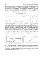
Fig. 6 shows the RTT measurements obtained in terms of the number of MCLK cycles elaps ed
at each distance and environment, exterior and corridor. Each mark in Fig. 6 represents the
mean of each group of 150 RTT measurements. The result is qualitatively consistent because,
as it was expected, the delay profile observed shifts to the right as the actual distance between
the two WLAN nodes increases, and it follows a linear form.
As Fig. 6 shows, although a direct path exists between the MS and the AP in all scenarios and
distances, the delay profile observed is spread around 4 MCLK cycles. Besides the random
behavior of the electronics, there are two main reasons: first of all, the frequency clock that
governs the MS and the AP is 44 MHz and 20 MHz, respectively. Secondly, because of the
multipath and the scatters of the environment, the direct path is not always the one selected by
WLAN adapters. Therefore, to estimate the distance between the MS and the AP, a statistical
estimator of the delay profile observed has to be selected. It will be discussed in the following
section.
6999 6992 6994 6996 6998 7999 7992 7994 7996 7998
9
9
19
19
29
29
39
39
49
Número de ciclos de MCLK
Distancia [m]
Exterior
Number of MCLK cycles
Distance
(a) Exterior
6999 6999 7999 7999 7919 7919
9
9
19
19
29
29
39
39
49
Número de ciclos de MCLK
Distancia [m]
Pasillo
Number of MCLK cycles
Distance
Corridor
(b) Corridor
Fig. 6. RTT measurements between two WLAN nodes in LOS at different distances in two
different scenarios, exterior and corridor.
2.2.2 AP processing time measurements
The AP processing time is measured in the two scenarios described above (exterior and
corridor) in order to check that the AP processing time is constant when the RTS/CTS
two frame exchange is performed. As the WLAN MAC chip set of the Linksys WRT54GL
802.11b/g is not for public access, in this section the Cisco AIR-PCM340 WLAN adapter is
used in AP mode. Therefore, a testing for this AP processing time approach was performed
224
Advances in Vehicular Networking Technologies
using two Cisco WLAN adapters, one acting as a MS and the other acting as an AP. The
PCB was in the AP. By using a driver designed by ourselves, based on the LORCON library,
the MS sends a RTS frame to the AP identified through the MAC address and it waits for the
corresponding CTS frame response. When the AP processing time is measured, the measuring
system was not disabled between two RTS/CTS frames exchange because the AP does not
know, a priori, the time the RTS frames arrival because they are not synchronized. As other
frames coming from other WLANs could start or finish the count, the AP processing time
measurements have to be filtered a posteriori, because the triggers that starts and finishes the
count could not match with our RTS/CTS frames exchange.
As the AP processing time is independent of distance, t he measurements were conducted for
a distance of 10 m between the two WLAN adapters in the two scenarios, exterior and corridor.
Number of MCLK cycles
Number of measurements
Corridor
(a) Zoom out
8489 8499 8999 8919 8929 8939 8949 8999 8969
9
99
199
199
299
299
399
399
Número de ciclos de MCLK
Número de Medidas
Pasillo
Exterior
Number of MCLK cycles
Number of measurements
Corridor
(b) Zoom in
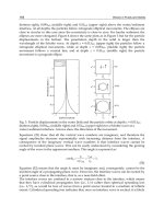
Fig. 7. AP processing time measurements in two different scenarios, exterior and corridor.
As Fig. 7 shows, there are mainly four different behaviors about AP processing time
measurements, which are around 0, 8500, 50000 and 65000 MCLK cycles. The extreme values,
0 and 65535 MCLK cycles, mean that the measuring system has not started the count before
reading the counters state and the count has overflow, respectively. Measurements around
50000 MCLK cycles are not due to the RTS/CTS frame exchange because this behavior does
not appear in the exterior environment, where there were not signals coming from other 802.11
devices. Measurements around 8500 MCLK cycles do not appear when the MS does not send
the RTS frames. Therefore, these measurements, around 8500 MCLK cycles, a re due to the
AP processing time. When a RTS/CTS frame exchange is performed, it is assumed that the
AP processing time is roughly constant because more than 50% of measurements, which are
around 8500 MCLK cycles, were exactly 8494 MCLK cycles, although this actual value of the
AP processing time is not needed to apply the ranging method we propose in next section.
3. Distance estimation in LOS
According to (Chen & Ling, 2002), the range resolution is determined by the bandwidth of the
transmitted signal when RTT measurements are used. High-precision location would require
large transmission bandwidths or the use of multiple frequency channels. Furthermore, when
using a 44 MHz clock as input of the measuring system to quantify the RTT measurements, the
maximum resolution achievable, if only one sample is taken, is hampered by that frequency
clock. Moreover, even in a LOS environment the RTT measurements have a random behavior
225
Distance Estimation based on 802.11 RTS/CTS Mechanism for Indoor Localization