Mass Transfer in Multiphase Systems and its Applications Part 6 pdf
Bạn đang xem bản rút gọn của tài liệu. Xem và tải ngay bản đầy đủ của tài liệu tại đây (1.03 MB, 40 trang )
Laminar Mixed Convection Heat and Mass Transfer with
Phase Change and Flow Reversal in Channels
189
boundary layer. As the air moves downstream, these forces become weak and the effect of
buoyancy forces becomes clear. As both thermal and solutal Grashof numbers are negative,
buoyancy forces act in the opposite direction of the upward flow and decelerate it near the
walls. This deceleration produces a flow reversal close to the channel walls at X = 2.31.
Buoyancy forces introduce a net distortion of the axial velocity profile compared to the case
of forced convection. The flow reversal is clear in Figure 4, which show the evolution of the
axial velocity, near the plates. Three different temperatures at the channel inlet are
represented in this figure: T
0
= 30°C (Gr
T
= -0.88.10
5
and Gr
M
=1.07.10
4
), 41°C (Gr
T
= -1.71.10
5
and Gr
M
= 0) and 50°C (Gr
T
= -2.29.10
5
and Gr
M
=-1.29.10
4
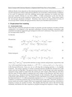
). We notice that the axial velocity
takes negative values for the last two cases over large parts of the channel length. Along
these intervals, air is flowing in the opposite direction of the entering flow. That change in
the flow direction gives rise to a recirculation cell and to the flow reversal phenomenon.
Figure 5 shows the streamlines for the vertical symmetric channel. Two recirculation cells
are present close to the channel entrance. Careful inspection of Fig. 5 show that the
streamlines contours in the recirculation cells are open near the plates. Indeed, these
streamlines are normal to the channel walls. Local velocity is then directed to these walls, as
condensation occurs here (Oualid et al., 2010b).
Fig. 3. Axial velocity profiles in the vertical symmetric channel for T
0
= 50°C and
φ
0
= 30%
(Oulaid et al., 2010b)
Fig. 4. Evolution of the axial velocity near the plates of the vertical symmetric channel for
φ
0
= 30% at Y=1.33 10
-4
(Oulaid et al., 2010b)
Mass Transfer in Multiphase Systems and its Applications
190
Fig. 5. Streamlines in the vertical symmetric channel for T
0
= 41°C and
φ
0
= 43.25% (Gr
T
= -
1.71.10
5
and Gr
M
= -10
4
) (Oulaid et al., 2010b).
For the inclined isothermal asymmetrically wetted channel, the flow structure is represented
in Fig. 6 by the axial velocity profiles for different inclination angles. Remember that for this
case only the lower plate (Y=0) is wet while the upper one is dry. The maximum of
distortion of U is obtained for the vertical channel, for which buoyancy forces takes their
maximum value in the axial direction. Fig. 6 show that flow reversal occurs for φ = 60° and
Fig. 6. Axial velocity profiles in the inclined isothermal asymmetrically wetted channel for
T
0
= 40°C and φ
0
= 45.5% (Gr
T
= -1.64 10
5
and Gr
M
= -10
4
) (Oulaid et al., 2010d).
Laminar Mixed Convection Heat and Mass Transfer with
Phase Change and Flow Reversal in Channels
191
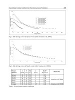
90°. This is clearer from Fig. 9, which presents the friction factor f at the lower wet plate in
the isothermal asymmetrically wetted channel. Negative values of f occur in the flow
reversal region. Streamlines presented in Fig. 8, show the recirculation cells near the lower
wet plate, where the airflow is decelerated due to its cooling. It can be seen clearly from Fig.
8 that the streamlines contours in the flow reversal region are not closed. Indeed, close to the
lower wet plate, airflow velocity is directed towards the channel wall. This velocity, which is
equal to the vapour velocity at the air-liquid interface V
e
, is shown in Fig. 9. It is noted that
V
e
is negative which indicate that water vapour is transferred from airflow towards the wet
plate. Thus, this situation corresponds to the condensation of the water vapour on that plate.
It is interesting to note that close to the channel entrance, (X < 4.37) the magnitude of V
e
for
forced convection (and the horizontal channel too) is larger than for the inclined channel;
while further downstream forced convection results in lower values of V
e
magnitude. This
inversion in V
e
tendency occurs at the end of the flow reversal region (X = 4.37). In this
region, as the channel approaches its vertical position, buoyancy forces slowdown airflow
thus, water vapour condensation diminishes.
Fig. 7. Axial evolution of the friction factor at the lower wet plate in the isothermal
asymmetrically wetted channel for T
0
= 40°C and φ
0
= 45.5% (Gr
T
= -1.64 10
5
and Gr
M
= -10
4
)
and different inclination angles (Oulaid et al., 2010d).
Fig. 8. Streamlines in the isothermal asymmetrically wetted channel for T
0
= 40°C and φ
0
=
45.5% (Gr
T
= -1.64 10
5
and Gr
M
= -10
4
) and different inclination angles (Oulaid et al., 2010d).
Mass Transfer in Multiphase Systems and its Applications
192
Fig. 9. Vapour velocity at the lower plate of the isothermal asymmetrically wetted channel
for T
0
= 40°C and φ
0
= 45.5% (Gr
T
= -1.64 10
5
and Gr
M
= -10
4
) and different inclination angles
(Oulaid et al., 2010d).
4.2 Thermal and mass fraction characteristics
Figure 10 presents the evolution of the latent Nusselt number (Nu
L
) at the wet plate of the
isothermal asymmetrically wetted inclined channel. Nu
L
is positive indicating that latent
heat flux is directed towards the wet plate. Thus, water vapour contained in the air is
condensed on that plate, as shown in Fig. 9. As the air moves downstream, water vapour is
removed from the air; thus, the gradient of mass fraction decreases, and that explains the
decrease in Nu
L
. In the first half of the channel, Nu
L
is less significant as the channel
approaches its vertical position, due to the deceleration of the flow by the opposing
buoyancy forces as depicted above. Close to the channel exit, the buoyancy forces
magnitude diminishes; hence, Nu
L
takes relatively greater values for the vertical channel
(Oulaid et al., 2010a). Figure 11 show the Sensible Nusselt number at the wet plate of the
isothermal asymmetrically wetted channel. It is clear that the buoyancy forces diminish heat
transfer. This diminution is larger in the recirculation zone. Figure 12 presents Sherwood
number at the wet plate of the isothermal asymmetrically wetted channel. The behaviour of
Sh resembles to that of Nu
S
, as Le ≈ 1 here.
Fig. 10. Latent Nusselt number at the wet plate of the isothermal asymmetrically wetted
inclined channel for T
0
= 40°C and φ
0
= 45.5% (Gr
T
= -1.64 10
5
and Gr
M
= -10
4
) and different
inclination angles (Oulaid et al., 2010d).
Laminar Mixed Convection Heat and Mass Transfer with
Phase Change and Flow Reversal in Channels
193
Fig. 11. Sensible Nusselt number Nu
S
at the wet plate of the isothermal asymmetrically
wetted inclined channel for T
0
= 40°C and φ
0
= 45.5% (Gr
T
= -1.64 10
5
and Gr
M
= -10
4
) and
different inclination angles (Oulaid et al., 2010d).
Fig. 12. Sherwood number Sh at the wet plate of the isothermal asymmetrically wetted
inclined channel for T
0
= 40°C and φ
0
= 45.5% (Gr
T
= -1.64 10
5
and Gr
M
= -10
4
) and different
inclination angles (Oulaid et al., 2010d).
4.3 Flow reversal chart
As stated in the introduction, flow reversal in heat-mass transfer problems was not studied
extensively in the literature. This phenomenon is an important facet of the hydrodynamics
of a fluid flow and its presence indicates increased flow irreversibility and may lead to the
onset of turbulence at low Reynolds number. Hanratty et al. (1958) and Scheele & Hanratty
(1962) were pioneers in experimental study of flow reversal in vertical tube mixed
convection. These authors have shown that the non-isothermal flow appears to be highly
unstable and may undergo its transition from a steady laminar state to an unstable one at
rather low Reynolds number. The unstable flow structure has shown, the ‘new equilibrium’
state that consisted of large scale, regular and periodic fluid motions. The condition of the
existence of flow reversal in thermal mixed convection flows were established by many
authors for different conditions (Wang et al. 1994; Nesreddine et al. 1998, Zghal et al. 2001;
Mass Transfer in Multiphase Systems and its Applications
194
Behzadmehr et al. 2003). As heat and mass transfer mixed convection is concerned, such
studies are rare as depicted in the introduction.
Fig. 13. Flow reversal chart for the vertical symmetric channel (a) γ = 1/35, (b) γ = 1/50 and
(c) γ = 1/65. (Oulaid et al. 2010b)
Laminar Mixed Convection Heat and Mass Transfer with
Phase Change and Flow Reversal in Channels
195
The conditions for the existence of flow reversal was established in the symmetric vertical
channel (Oulaid et al., 2010b) and the isothermal asymmetrically wetted inclined channel
(Oulaid et al., 2010d). For a given Re we varied T
0
(i.e. Gr
T
) at fixed Gr
M
(i.e. φ
0
) in asequence
of numerical experiments until detecting a negative axial velocity. All the considered
combinations of temperature and mass fraction satisfy the condition for the application of
the Oberbeck-Boussinesq approximation, as the density variations do not exceed 10%. These
series of numerical experiments enabled us to draw the flow reversal charts for different
aspect ratios of the channel (γ = 1/35, 1/50 and 1/65). These flow reversal charts are
presented in Figs 13-14. These charts would be helpful to avoid the situation of unstable
flow associated with flow reversal. The flow reversal charts are also expected to fix the
validity limits of the mathematical parabolic models frequently used in the heat-mass
transfer literature (Lin et al., 1988; Yan et al., 1991; Yan and Lin, 1991; Debbissi et al., 2001;
Yan, 1993; Yan et al., 1990; Yan and Lin, 1989; Yan, 1995).
Fig. 14. Flow reversal chart in the isothermal asymmetrically wetted inclined channel for
Gr
M
= -10
4
and γ = 1/65 (Oulaid et al. 2010d)
5. Asymmetrically cooled channel
For the asymmetrically cooled parallel-plate channel, the plates are subject to the boundary
condition
BC3 (i.e. one of the plates is wet and maintained at a fixed temperature T
w
= 20°C,
while the other is dry and thermally insulated). The Reynolds number is set at 300 and the
channel's aspect ratio is γ = 1/130 (L =2m).
5.1 Flow structure
The streamlines for the asymmetrically cooled vertical channel is presented in Fig. 15. This
figure shows the recirculation cell, which is induced by buoyancy forces. The dimension of
this recirculation cell is more significant than in the case of the isothermal channel (Figs. 5
and 8). The recirculation cell occupies a larger part of the channel and its eye is closer to the
channel axis. The flow structure is strongly affected by the buoyancy forces. These forces
induce a momentum transfer from the wet plate, where the flow is decelerated, towards the
dry plate, where the flow is accelerated (Kassim et al. 2010a).
Mass Transfer in Multiphase Systems and its Applications
196
0
.
0
1
1
9
7
6
9
0
.
0
0
6
8
6
5
3
2
0
.
0
0
2
6
0
5
6
9
4
.
9
9
0
2
7
E
-
0
5
-
0
.
0
0
1
2
9
0
9
4
-
0
.
0
0
2
1
3
2
4
7
-0.00141932
0 0.005 0.01 0.015
0
0.2
0.4
0.6
0.8
1
1.2
1.4
1.6
1.8
2
x(m)
y(m)
Fig. 15. Streamlines in asymmetrically cooled vertical channel for T
0
=70°C and φ
0
= 70%
(Gr
T
= - 1’208’840 and Gr
M
= -670’789) (Kassim et al. 2010a)
5.2 Thermal and mass fraction characteristics
The vapour mass flux at the liquid-air interface is shown in Figure 16. The represented cases
correspond to vapour condensation (water vapour contained in airflow is condensed at the
isothermal wetted plate in all cases). For
φ
0
= 10%, phase change and mass transfer at the
liquid-air interface is weak, thus condensed mass flux decreases rapidly and stretches to
zero. Considering the other cases (
φ
0
= 30% or 70%) the behaviour of the condensed mass
flux is complex. It exhibits local extrema, which are more pronounced as
φ
0
is increased. Its
local minimum occurs at the same axial location of the recirculation cell eye (Fig. 15). Thus,
it can be deduced that the increase of the vapour mass flux towards its local maximum is
attributed to the recirculation cell. The latter induces a fluid mixing near the isothermal plate
and thus increases condensed mass flux. As the recirculation cell switches off, the
condensed mass flux decreases due to the boundary layer development.
0 0.5 1 1.5 2
-0.001
0
0.001
0.002
0.003
0.004
10%
30%
70%
Forced convection (70%)
2
m"(kg / s.m )
•
x
(
m
)
Fig. 16. Vapour mass flux at the wet plate in asymmetrically cooled vertical channel of T
0
=
70°C and different inlet humidity φ
0
= 10% (Gr
T
= - 1’180’887 and Gr
M
= - 24’359), 30% (Gr
T
= -
1’189’782 and Gr
M
= - 226’095) and 70% (Gr
T
= - 1’208’840 and Gr
M
= - 670’789) (Kassim et al.
2010a)
Laminar Mixed Convection Heat and Mass Transfer with
Phase Change and Flow Reversal in Channels
197
Figure 17 presents axial development of airflow temperature at the channel mid-plane (y=
0.0068m). Airflow is being cooled in all cases as it goes downstream, due to a sensible heat
transfer from hot air towards the isothermally cooled plate. The airflow temperature at the
channel mid-plane exhibits two local extremums near the channel entrance. These
extremums are more pronounced for φ
0
= 70%. In this case the local minimum of air
temperature is 44.24°C which occurs at x = 0.092m and the local maximum is 46.59°C which
occurs at x = 0.208m. These axial locations are closer to that corresponding to local minimum
and maximum of the condensed mass flux (Fig. 16). Once again, it is clear that the
existenceof local extremums of air temperature at the channel mid-plane is related to the
fluid mixing induced by flow reversal near the isothermal wet plate. This fluid mixing
increases the condensed mass flux, thus the airflow temperature increases. Indeed, vapour
condensation releases latent heat, which is partly absorbed by airflow. Moreover, close to
the channel inlet, airflow at the channel mid-plane is cooler as φ
0
is increased. In this region
the buoyancy forces decelerate the upward airflow and induce flow reversal and thus,
increase the air-cooling through sensible heat transfer towards the isothermal plate (Kassim
et al. 2010a).
0 0.5 1 1.5 2
20
30
40
50
60
70
80
10%
30%
70%
Forced convection
y/L = 0.0034
x
(
m
)
T(°C)
Fig. 17. Airflow temperature at the mid-plane (y = 0.0074m) of the asymmetrically cooled
vertical channel for T
0
= 70°C and different inlet humidity φ
0
= 10% (Gr
T
= - 1’180’887; Gr
M
= -
24’359), 30% (Gr
T
= - 1’189’782; Gr
M
= - 226’095) and 70% (Gr
T
= - 1’208’840; Gr
M
= - 670’789)
(Kassim et al. 2010a)
Axial evolution of the local latent Nusselt number Nu
L
at the isothermal plate is represented
in Fig. 18. For
φ
0
= 10%, Nu
L
diminishes and stretches to zero at the channel exit, as phase
change and mass transfer at the liquid-air interface is weak (Fig. 16). The axial evolution of
Nu
L
for
φ
0
= 30% and 70%, is more complex and exhibits local minimum and maximum.
The positions of these extremums, which are the same as for the vapour mass flo rate at the
liquid-air interface (Fig. 16), depend on
φ
0
and are more pronounced for
φ
0
= 70%.
Furthermore, the development of Nu
L
and m
is analogous. Thus, the occurrence of the local
extremums of Nu
L
is due to the interaction between the vapour condensation and flow
reversal as explained above.
Mass Transfer in Multiphase Systems and its Applications
198
0 0.5 1 1.5 2
-5
0
5
10
15
20
25
30
10%
30%
70%
x (m)
Nu
L
Fig. 18. Latent Nusselt number at the wet plate of the asymmetrically cooled vertical channel
for T
0
= 70°C and different inlet humidity φ
0
= 10% (Gr
T
= - 1’180’887; Gr
M
= - 24’359), 30%
(Gr
T
= - 1’189’782; Gr
M
= - 226’095) and 70% (Gr
T
= - 1’208’840; Gr
M
= - 670’789) (Kassim et al.
2010a)
6. Insulated walls
The channel walls are subject to the boundary condition BC4 (i.e., both of the plates are
thermally insulated and wet). In this case, an experimental study was conducted and its resuts
are compared to the numerical one. Detailed description of the experimental setup is given by
Cherif et al. (2010). Only some important aspects of this setup are reported here. The channel is
made of two square stainless steel parallel plates (50cm by 50cm) and two Plexiglas
rectangular parallel plates (50cm by 5cm). Thus, the channel's aspect ratio is γ = 1/10. The
channel is vertical and its steel plates are covered on their internal faces with falling liquid
films. In order to avoid dry zones and wet the plates uniformly, very thin tissues support these
films. Ambient air is heated through electric resistances and upwards the channel, blown by a
centrifugal fan, via an settling box equipped with a honeycomb. Airflow and water film
temperature are measured by means of Chromel-Alumel (K-type) thermocouples. For the
liquid films, ten thermocouples are welded along each of the wetted plates. For the airflow, six
thermocouples are placed on a rod perpendicular to the channel walls. This rod may be moved
vertically in order to obtain the temperature at different locations. The liquid flow rate is low
and a simple method of weighing is sufficient to measure it. The evaporated mass flux was
obtained by the difference between the liquid flow rate with and without evaporation (Cherif
et al, 2010; Kassim et al. 2009; Kassim et al. 2010b). The liquid film flow rate was set between
1.55 10
-4
kg.s
-1
.m
-1
and 19.4 10
-4
kg.s
-1
.m
-1
. These values are very low compared to the
considered mass fluxes in Yan (1992; 1993). Thus, it is expected that the zero film thickness model
will be valid. The comparison of the numerical and experimental results is conducted for
laminar airflow. The Reynolds number is set at 1620 (U
0
= 0.27 m/s).
The airflow temperature is presented in Fig. 19 at three different axial locations. It is clear
that the concordance between the experimental measurements and the numerical results is
satisfactory. This concordance is excellent at the plates and close to it. Nevertheless, the
difference between these results does not exceed 8% elsewhere. It is noted that airflow is
Laminar Mixed Convection Heat and Mass Transfer with
Phase Change and Flow Reversal in Channels
199
cooled as it upwards the channel. This cooling essentially occurs in the vicinity of the wet
plates. The wet plates temperature profile is presented in Fig. 20. It should be noted that, in
the experimental study, T
w
is the water film temperature. The comparison between the
measurements and the numerical results is good, as the difference is less than 1.5%. It can be
deduced that the assumption of extremely thin liquid film, adopted in the numerical model,
is reliable here. On the other hand, it is noted that the liquid film is slightly cooled and then
a bit heated in contact with the hot airflow. It is important to remind that air enters the
channel at x=0m while the water film enters at x=0.5m. However, the water film
temperature remains quasi-constant within 2.5°C. It can be deduced that air is cooled mostly
by latent heat transfer associated to water evaporation. The global evaporated mass flux is
presented in Fig. 21 with respect to the inlet air temperature T
0
. This mass flux is calculated
in the numerical study by the following equation,
0
1
L
ev e
mVdx
L
ρ
•
=
∫
(25)
Experimentations were performed for three inlet air temperature 30, 35 et 45°C. Fig. 21
shows that the evaporated mass flux increases as the inlet air temperature is increased. This
is attributed to the increase of sensible heat transfer from the airflow to the water film,
which results in mass transfer from the film to the airflow associated with water
evaporation. Meticulous examination of Fig. 21 reveals that numerical calculation predicts
well the measured evaporated mass flux for T
0
= 30°C. For larger inlet air temperature, the
mathematical model underestimates the evaporated mass flux. Indeed the discrepancy
between the calculations and the measurements increases with T
0
. It is believed that this is
due to the calculation method. Indeed, in Eq 25 the density is considered constant and
calculated at the reference temperature (obtained by the one third rule). However, global
agreement between the calculations and the measurements is found in Fig. 21 as the
discrepancy does not exceed 10%.
0 0.01 0.02 0.03 0.04 0.05
16
20
24
28
32
36
x=0.05Numérique
x=0.05Experimental
x=0.25Numérique
x=0.25Experimental
x=0.45Numérique
x=0.45Experimental
y
(
m
)
T
g
(°C)
Fig. 19. Airflow temperature profiles at different axial locations for the insulated parallel-
plate vertical channel (Kassim et al., 2010b). Experimental conditions: u
0
= 0.27m/s, Re = 1620,
water flow rate =1.5 l/h, inlet liquid temperature= 17.7°C, ambient air humidity = 41% and
temperature = 18.2 °C, inlet airflow humidity
φ
0
= 16% and temperature T
0
= 45°C.
Mass Transfer in Multiphase Systems and its Applications
200
0 0.1 0.2 0.3 0.4 0.5
17
17.5
18
18.5
19
19.5
20
20.5
Numérique
experimental
x(m)
T
w
(°C)
Fig. 20. Wall temperature for the insulated parallel-plate vertical channel (Kassim et al.,
2009). Experimental conditions: u
0
= 0.27m/s, Re = 1620, water flow rate = l/h, inlet liquid
temperature= 18°C, ambient air humidity = 45% and temperature = 19 °C, inlet airflow
humidity φ
0
= 16 and temperature T
0
= 45°C.
20 25 30 35 40 45 50
6
6.5
7
7.5
8
8.5
9
9.5
10
10.5
Calculations
Experimental
T
0
(°C)
m
ev
x10
-5
(kg/m
2
S)
Fig. 21. Evaporated mass flux at the liquid-air interface (Kassim et al., 2009). Experimental
conditions: u
0
= 0.27m/s, Re = 1620, water flow rate =1 l/h, inlet liquid temperature= 18°C,
ambient air humidity = 45% and temperature = 19 °C.
7. Conclusion
Heat and mass transfer mixed convection in channels, with special emphasis on phase
change and flow reversal, is considered. The literature review reveals that the flow reversal
phenomenon in such problems was not extensively studied. Some recent numerical and
experimental work of the authors are reported. The chanel is a parallel-plate one, which may
be isothermally cooled or thermally insulated. Water liquid films stream along one or both
of the plates. The effects of buoyancy forces on the flow structure as well as on heat and
mass transfer characteristics are analysed. The conditions of the occurrence of flow reversal
are particularly addressed. Flow reversal charts, which specify these conditions, are given.
The comparison between the numerical and experimental results is satisfactory. However,
Laminar Mixed Convection Heat and Mass Transfer with
Phase Change and Flow Reversal in Channels
201
the numerical study is limited by its hypotheses. Future research may concern more
elaborated mathematical models taking into account the variability of the thermo-physical
properties and the thickness of the liquid film. On the other hand, as flow reversal may
induce flow instability, a transient mathematical model, such as the low Reynolds number
turbulence model may be more appropriate. Finally, more experimental investigations of
the considered problem is needed.
8. Acknowledgements
The experimental study was conducted at the Laboratoire d'Energétique et des Transferts
Thermiques et Massiques, Faculty of Sciences, Bizerte (Tunisa) . The financial support of the
Morocco-Tunisian Cooperation Program (Grant no MT/06/41) is acknowledged.
9. Nomenclature
b half width of the channel (m)
C dimensionless mass fraction, = (ω – ω
0
) . ( ω
w
– ω
0
)
-1
D mass diffusion coefficient [m².s
-1
]
D
h
hydraulic diameter, = 4b [m]
f friction factor
g gravitational acceleration [m.s
-2
]
Gr
M
mass diffusion Grashof number, = g.β
*
.
D
h
3
.(ω
w
– ω
0
).ν
-2
Gr
T
thermal Grashof number, = g.β.D
h
3
.
(T
w
– T
0
).ν
-2
h local heat transfer coefficient [W.m
-2
.K
-1
]
h
m
local mass transfer coefficient [m.s
-1
]
h
fg
latent heat of vaporization [J.kg
-1
]
k thermal conductivity [W m
-1
K
-1
]
L channel height [m]
m
vapour mass flux at the liquid-gas interface [kg.s
-1
.m
-2
]
M
a
molecular mass of air [kg.kmol
-1
]
M
v
molecular mass of water vapour [kg.kmol
-1
]
N buoyancy ratio, = Gr
M
/Gr
T
Nu
S
local Nusselt number for sensible heat transfer
Nu
L
local Nusselt number for latent heat transfer
p pressure
P
m
modified dimensionless pressure, = (p + ρ
0
g x).(ρ
0
u
0
2
)
-1
Pr Prandtl number, = ν/α
q" heat flux [W.m
-2
]
Re Reynolds number, = u
0
.D
h
.ν
-1
R
Nu
ratio of latent to sensible Nusselt numbers, = Nu
L
/Nu
S
Sc Schmidt number, = ν/D
Sh Sherwood number
T temperature [K]
u, v velocity components [m.s
-1
]
U, V dimensionless velocity components, = u/u
0
, v/u
0
V
e
dimensionless transverse vapour velocity at the air-liquid interface.
Mass Transfer in Multiphase Systems and its Applications
202
x, y axial and transverse co-ordinates [m]
X, Y dimensionless axial and transverse co-ordinates, = x/D
h
, y/D
h
Greek symbols
α thermal diffusivity [m² s
-1
]
β coefficient of thermal expansion,
β
*
coefficient of mass fraction expansion,
γ aspect ratio of the channel, = 2b/L
Θ dimensionless temperature, = (T - T
0
)/(T
w
- T
0
)
ν kinematic viscosity [m
2
.s
-1
]
ρ density [kg.m
-3
]
φ relative humidity (%)
φ inclination angle of the channel
ω mass fraction [kg of vapour/ kg of mixture]
Subscripts
a relative to the gas phase (air)
L relative to latent heat transfer
ℓ relative to the liquid phase
m mean value
0 at the inlet
S relative to sensible heat transfer
sat at saturation conditions
v relative to the vapour phase
w at the wall
10. References
Agunaoun A., A. Daif, R. Barriol, & M. Daguenet (1994), Evaporation en convection forcée
d’un film mince s´écoulant en régime permanent, laminaire et sans ondes, sur une
surface plane inclinée, Int. J. Heat Mass Transfer, 37, 2947–2956.
Agunaoun A., A. IL Idrissi, A. Daıf, & R. Barriol (1998) Etude de l’évaporation en convection
mixte d’un film liquide d’un mélange binaire s’écoulant sur une plaque inclinée
soumise à un flux de chaleur constant, Int. J. Heat Mass Transfer, 41, 2197–2210.
Ait Hammou Z., B. Benhamou, N. Galanis & J. Orfi (2004), Laminar mixed convection of
humid air in a vertical channel with evaporation or condensation at the wall, Int. J.
Thermal Sciences, 43, 531-539.
Azizi Y., B. Benhamou, N. Galanis & M. El Ganaoui (2007), Buoyancy effects on upward and
downward laminar mixed convection heat and mass transfer in a vertical channel»,
Int. J. Num. Meth. Heat Fluid Flow, 17, 333-353.
Baumann W.W. & Thiele F., (1990) Heat and mass transfer in evaporating two-component
liquid film flow, Int. J. Heat Mass Transfer, 33, 273–367.
Behzadmehr A., Galanis N., Laneville A., (2003) Low Reynolds number mixed convection in
vertical tubes with uniform wall heat flux, Int. J. Heat Mass Transfer 46, 4823–4835.
Ben Nasrallah S. & Arnaud G. (1985) Évaporation en convection naturelle sur une
plaque verticale chauffée à flux variable. Journal of Applied Mathematics and Physics,
36, 105-119.
Laminar Mixed Convection Heat and Mass Transfer with
Phase Change and Flow Reversal in Channels
203
Boulama, K., Galanis, N., (2004) Analytical solution for fully developed mixed convection
between parallel vertical plates with heat and mass transfer, J. Heat Transfer, 126,
381–388.
Burmeister, L.C., (1993) Convective Heat Transfer, J. Wiley, New York.
Chang C. J., Lin T. F. & Yan W. M., (1986) Natural convection flows in a vertical open tube
resulting from combined buoyancy effects of thermal and mass diffusion, Int. J.
Heat Mass Transfer, 29, 1453-1552.
Chow, L.C., & Chung, J.N. (1983), Evaporation of water into laminar stream of air and
superheated steam, Int. J. Heat Mass Transfer, 26, 373-380.
A. S. Cherif, M. A. Kassim, B. Benhamou, S. Ben Jabrallah, S. Harmand, J.P. Courriou
"Experimental Study of Mixed Convection Heat and Mass Transfer in a Vertical
Channel with Film Evaporation", Int. Journal Thermal Science, Submitted June 2010.
Fedorov A. G., R. Viskanta & A. A. Mohamad (1997) Turbulent heat and mass transfer in
assymetrically heated, vertical parallel plate channel, Int. J. Heat and Fluid Flow, 18,
307–315.
Feddaoui M., Mir A. & Belahmidi E. (2003) Cocurrent turbulent mixed convection heat and
mass transfer in falling film of water inside a vertical heated tube, Int. J. Heat Mass
Transfer, 46, 3497–3509.
Fuji, T., Kato, Y. & Bihara, K. (1977), Expressions of transport and thermodynamic properties of
air, steam and water, Sei San Ka Gaku Ken Kuu Jo, Report no 66, Kyu Shu
University, Kyu Shu, Japan.
Gebhart B. & Pera L. (1971), The nature of vertical natural convection flows resulting from
the combined buoyancy effects of thermal and mass diffusion, Int. J. Heat Mass
Transfer, 14, 2025-2050.
Gebhart B., Jaluria Y., Mahajan R. L. & Sammakia B. (1988), Buoyancy-induced flows and
transport, Hemisphere Pub. Co., New York.
Hanratty T. J., Rosen E. M., Kabel R. L. (1958), Effect of heat transfer on flow field at low
Reynolds numbers in vertical tubes, Indust. Engrg. Chem., 50, 815-820.
He S., An P., Li J. & Jackson J.D. (1998) Combined heat and mass transfer in a uniformly
heated vertical tube with water film cooling, Int. J. Heat Fluid Flow, 19, 401-417.
Hubbard G.L., Denny, V.E. & Mills, A.F. (1975), Droplet evaporation: effects of transients
and variable properties, Int. J. Heat Mass Transfer, 18, 1003-1008.
Huang, C.C. Yan, W.M. and Jang, J.H. (2005), Laminar mixed convection heat and mass
transfer in a vertical rectangular duct with film evaporation and condensation, Int.
J. Heat Mass Transfer, 48, 1772-1784.
Kassim M. A., Benhamou B. & Harmand S. (2010a) Combined heat and mass transfer with
phase change in a vertical channel, Computational Thermal Science, 2, 299-310.
Kassim M. A., Cherif A. S., Benhamou B., Harmand S. et Ben Jabrallah S. (2010b) étude
numérique et expérimentale de la convection mixte thermosolutale accompagnant
un écoulement d’air laminaire ascendant dans un canal vertical adiabatique. 1er
Colloque International Francophone d’Energétique et Mécanique (CIFEM’2010), Saly,
17-19 mai 2010, Senegal.
Kassim M. A., Benhamou B., Harmand S., Cherif A. S., Ben Jabrallah S. (2009) " Etude
numérique et expérimentale sur les transferts couplés de chaleur et de masse avec
changement de phase dans un canal vertical adiabatique " IXème Colloque Inter-
universitaire Franco–Québécois Thermique des systèmes CIFQ2009, 18-20 mai 2009,
Lille, France
Mass Transfer in Multiphase Systems and its Applications
204
Laaroussi N., Lauriat G. & Desrayaud G. (2009), Effects of variable density for film
evaporation on laminar mixed convection in a vertical channel, Int. J. Heat Mass
Transfer, 52, 151-164.
Lin T.F., Chang C.J., & Yan W.M. (1988), Analysis of combined buoyancy effects of thermal
and mass diffusion on laminar forced convection heat transfer in a vertical tube,
ASME J. Heat Transfer 110, 337–344.
Lin, J. N., Tzeng, P. Y., Chou, F. C., Yan, W. M. (1992), Convective instability of heat and
mass transfer for laminar forced convection in the thermal entrance region of
horizontal rectangular channels, Int. J. Heat Fluid Flow, 13, 250-258.
Maurya R. S., Diwakar S. V., Sundararajan T., & Das Sarit K. (2010), Numerical investigation
of evaporation in the developing region of laminar falling film flow under constant
wall heat flux conditions, Numerical Heat Transfer, Part A, 58: 41–64
Maré, T., Galanis, N., Voicu, I., Miriel, J., Sow, O., (2008) Experimental and numerical study
of mixed convection with flow reversal in coaxial double-duct heat exchangers,
Exp. Therm. Fluid Sci., 32, 1096–1104.
Mezaache H. & Daguenet M. (2000) Etude numérique de l’évaporation dans un courant
d’air humide laminaire d’un film d’eau ruisselant sur une plaque inclinée, Int. J.
Thermal Sci., 39, 117–129.
Minkowycz, W.J. & Sparrow E.M. (1966), Condensation heat transfer in the presence of non-
condensable, interfacial resistance, superheating, variable properties, and diffusion,
Int. J. Heat Mass Transfer, 9, 1125–1144
Nesreddine, H., Galanis, N. & Nguyen, C.T., (1998) Effects of axial diffusion on laminar heat
transfer with low Péclet numbers in the entrance region of thin vertical tubes.
Numer. Heat Transfer Part A, 33, 247–266.
Nelson D. J. & Wood B. D. (1989) Combined heat and mass transfer natural convection
between vertical parallel plates, Int. J. Heat Mass Transfer, 328, 1779–1789.
Nguyen, C.T., Maiga, S.E., Landry, M., Galanis, N., Roy, G. (2004) Numerical investigation
of flow reversal and instability in mixed laminar vertical tube flow, Int. J. Therm.
Sci., 43, 797–808.
Nusselt, W. (1916) Die Oberflchenkondensation des Wasserdampfes, Z. Ver. Deutch. Ing.
60 541–546. 569–575.
Oulaid O., B. Benhamou, N. Galanis (2010a), Combined buoyancy effects of thermal and
mass diffusion on laminar forced convection in a vertical isothermal channel,
Computational Thermal Science, 2, 125-138.
Oulaid O., Benhamou B., Galanis N. (2010b), Mixed Convection Heat and Mass Transfer
with Phase Change and Flow Reversal in Channels, Int. J. Heat Fluid Flow, 31,
711-721 (doi:10.1016/j.ijheatfluidflow.2010.04.007).
Oulaid O., Benhamou B., Galanis N. (2010c), Simultaneous heat and mass transfer in
inclined channel with asymmetric conditions, 14
th
Int. Heat Transfer Conference
IHTC14, Washigton USA, 8-13 August 2010
Oulaid O., Benhamou B., Galanis N. (2010d), Simultaneous heat and mass transfer in
inclined channel with asymmetric conditions, Journal of Applied Fluid Mechanics, in
press.
Oulaid Othmane (2010), Transferts couplés de chaleur et de masse par convection mixte avec
changement de phase dans un canal, Ph. D. Thesis, Jointly presented at Cadi Ayyad
Univesity Marrakech (Morocco) and University of Sherbrooke (Canada).
Laminar Mixed Convection Heat and Mass Transfer with
Phase Change and Flow Reversal in Channels
205
Oulaid O., B. Benhamou, N. Galanis (2009), "Effet de l’inclinaison sur les transferts couplés
de chaleur et de masse dans un canal" IXème Colloque Inter-Universitaire Franco–
Québécois Thermique des systèmes CIFQ2009, 18-20 mai 2009, Lille, France
Oulaid O., B. Benhamou (2007), Effets du rapport de forme sur les transferts couples de
chaleur et de masse dans un canal vertical, Actes des 13èmes Journées Internationales
de Thermique - JITH07, pp. 76-80, Albi, France, 28-30 Aout 2007.
(
Patankar, S. V. (1980), Numerical Heat Transfer and Fluid Flow, Hemisphere/McGraw-Hill.
Patankar, S. V. (1981), A calculation procedure for two-dimensional elliptic situations,
Numerical Heat Transfer, 4, 409-425.
Salah El-Din, M.M., (1992) Fully developed forced convection in vertical channel with
combined buoyancy forces, Int. Comm. Heat Mass Transfer, 19, 239–248.
Scheele G. F., Hanratty T. J. (1962), Effect of natural convection on stability of flow in a
vertical pipe, J. Fluid Mech., 14, 244-256.
Siow, E. C., Ormiston, S. J., Soliman, H. M. (2007), Two-phase modelling of laminar film
condensation from vapour-gas mixtures in declining parallel-plate channels, Int. J.
Thermal Sciences, 46, 458-466.
Suzuki K., Y. Hagiwara & T. Sato (1983), Heat transfer and flow characteristics of two-
component annular flow, Int. J. Heat Mass Transfer, 26, 597-605.
Shembharkar T. R. & Pai B. R., (1986) Prediction of film cooling with a liquid coolant, Int. J.
Heat Mass Transfer, 29, 899-908.
Tsay Y. L., Li T. F. et Yan W. M. (1990) Cooling of falling liquid film through interfacial heat
and mass transfer. Int. J. Multiphase Flow, 16, 853-865.
Vachon M. (1979) Étude de l’évaporation en convection naturelle. Thèse de Doctorat,
Université de Poitiers, Poitiers, France.
Volchkov E. P., Terekhov V. V., Terekhov V. I. (2004), A numerical study of boundary layer
heat and mass transfer in a forced convection of humid air with surface steam
condensation, Int. J. Heat Mass Transfer, 47, 1473-1481.
Wang, M., Tsuji, T., Nagano, Y., (1994) Mixed convection with flow reversal in the thermal
entrance region of horizontal and vertical pipes, Int. J. Heat Mass Transfer, 37,
2305–2319. 656
Yan W.M., Y.L. Tsay & T.F. Lin (1989), Simultaneous heat and mass transfer in laminar
mixed convection flows between vertical parallel plate with asymmetric heating,
Int. J. Heat Fluid Flow 10, 262–269.
Yan W.M. & Lin T.F. (1989), Effects of wetted wall on laminar mixed convection heat
transfer in a vertical channel, J. Thermophys. Heat Transfer, 3, 94–96.
Yan W. M., Y. L. Tsay & T. F. Lin (1990), Effects of wetted walls on laminar natural
convection between vertical parallel plate with asymmetric heating, Applied
Scientific Research, 47, 45-64.
Yan W.M. (1991), Mixed convection heat transfer enhancement through latent heat transport
in vertical parallel plate channel flows, Can J. Chem. Eng., 69, 1277–1282.
Yan W. M., T. F. Lin & Y. L. Tsay (1991), Evaporative cooling of liquid film through
interfacial heat and mass transfer in a vertical channel - I. Experimental study, Int. J.
Heat Mass Transfer, 34, 1105-1111.
Yan W. M. & Lin T. F. (1991), Evaporative cooling of liquid film through interfacial heat and
mass transfer in a vertical channel - II. Numerical study, Int. J. Heat Mass Transfer
34, 1113-1124.
Mass Transfer in Multiphase Systems and its Applications
206
Yan W. M. (1992), Effect of film evaporation laminar mixed convection heat and mass
transfer in a vertical channel, Int. J. Heat Mass Transfer, 35, 3419–3429.
Yan, W.M. (1993), Mixed convection heat transfer in a vertical channel with film
evaporation, Canadian J. Chemical Engineering, 71, 54-62.
Yan W.M. (1995a), Turbulent mixed convection heat and mass transfer in a wetted channel,
ASME J. Heat Transfer 117, 229–233.
Yan W. M. (1995b), Effects of film vaporization on turbulent mixed convection heat and
mass transfer in a vertical channel, Int. J. Heat Mass Transfer, 38, 713-722.
Yan W. M. & Soong C. Y. (1995) Convective heat and mass transfer along an inclined heated
plate with film evaporation, Int. J. Heat Mass Transfer, 38, 1261-1269.
10
Liquid-Liquid Extraction With and
Without a Chemical Reaction
Claudia Irina Koncsag
1
and Alina Barbulescu
2
1
University of Warwick
2
“Ovidius” University of Constanta
1
United Kingdom
2
Romania
1. Introduction
The extraction of mercaptans with alkaline solution is accompanied by a second- order
instantaneous reaction. As explained in Section 2.2, in this case, the mass transfer
coefficients can be calculated as for the physical extraction, since the mass transfer is much
slower than the reaction rate.The liquid-liquid extraction is a mass transfer process between
two phases. One liquid phase is the feed consisting of a solute and a carrier. The other phase is
the solvent. The extraction is understood to be a transfer of the solute from the feed to the
solvent. During and at the end of the extraction process, the feed deprived of solute becomes
a raffinate and the solvent turns into extract. Extraction is a separation process aiming to
purify the feed or to recover one or more compounds from it.
The mass transfer mechanism can be described by the well known double film theory, the
penetration theory or the surface renewal theory. Especially the stationary double film
theory describes most accurately the liquid-liquid extraction. With the means of this theory,
the dimensioning of the extraction equipment can be done.
Sometimes, over the physical extraction process, a chemical reaction is superposed.
Depending on the reaction rate compared with the mass transfer rate, the process can be
considered driven by the mass transfer or by the chemical reaction. Also, in some cases, the
chemical reaction has an effect of enhancement for the extraction, contributing to speed up
the process. As a consequence, the dimensioning of the equipment is different.
Many studies have been performed in the last decades for the mathematical modelling of
the processes. Accurate correlations between physical properties (densities, density
difference, interfacial tension), and dimensions involved in the extraction equipment
dimensioning: the drop size diameter, the characteristic velocity of the drop and the slip
velocity of the phases were worked out. A smaller number of correlations are available for
the calculation of the mass transfer coefficients. Some of the elements needed for the
dimensioning of the extractors would be determined experimentally, if a certain accuracy is
expected. The experiment is compulsory for the mass transfer coefficients when a new type
of equipment is used.
The present work exemplifies the theoretical aspects of the liquid-liquid extraction with and
without a chemical reaction and the dimensioning of the extractors with original
Mass Transfer in Multiphase Systems and its Applications
208
experimental work and interpretations. The experiment involved extraction of acid
compounds from sour petroleum fractions with alkaline solutions in structured packing
columns. Such an example is useful for understanding the principles of dimensioning the
extraction equipment but also offers a set of experimental data for people developing
processes in petroleum processing industry. A simple, easy to handle model composed by
two equations was developed for the mercaptans (thiols) extraction.
2. Theoretical aspects
The immiscible liquid phases put in contact (the feed and the solvent) form a closed system
evolving towards the thermodynamic equilibrium. According to the Gibbs law:
23223lc f
=
+−=+−=, (1)
the system can be defined by three parameters (l=3), the number of components being c=3
(solvent, solute and carrier), and the phases number f=2. Usually, the parameters taken into
account are the temperature (T), the concentration of the solute in the raffinate (x) and the
concentration in the extract (y). So, the equilibrium general equation in this case is:
()
tconst
yfx
=
=
(2)
The equilibrium equation can have different forms, but most frequently, if the liquid phases
are completely immiscible and the solute concentration is low, the Nernst law describes
accurately the thermodynamic equilibrium:
y
mx
=
⋅ , (3)
where m is the repartition coefficient of the solute between the two phases. The Nernst law
can be applied also at higher concentration of the solute but in a narrow range of
concentrations.
y
A
y
Ai
x
Ai
x
A
y
A
y
Ai
x
Ai
x
A
y
Ai
x
Ai
a) b) c)
Fig. 1. The evolution of the solute concentration in the vicinity of the interface in a closed
system
The double stationary film theory of Whitman leads to very good practical results for the
determination of mass transfer coefficients. According to this theory, the phases are
separated by an interface and a double film (one of each phase) adheres to this interface. The
Liquid-Liquid Extraction With and Without a Chemical Reaction
209
mass transfer takes place exclusively in this double stationary film by the molecular
diffusion mechanism. In the bulk of both phases, the concentration of the solute is
considered uniform as a consequence of perfect mixing.
In Fig.1, the evolution in time is presented for a closed system approaching the equilibrium,
in the light of double film theory. Notations x
Ai
and y
Ai
are for the concentration at the
interface in raffinate and extract respectively; x
A
and y
A
denote the concentration of the
solute A in the bulk of the raffinate and of the extract respectively. In Fig.1, the mass transfer
is presented in a closed system in evolution from the initial state a to the final equilibrium
state c. The concentrations at the interface are constant and linked by the equilibrium
equation since the concentration of the solute in the bulk feed /raffinate decreases and the
concentration of the solute in the bulk solvent/ extract increases in time until equalling the
equilibrium concentrations. If the system is open, y
A
and x
A
are constant in time (the regime
becomes stationary) and the system is maintained in the state a.
2.1 Mass transfer coefficients in physical extraction
In liquid-liquid extraction, the best mechanism describing the mass transfer is the
unicomponent diffusion (the solute A diffusing in one direction without a counter diffusion).
According to Maxwell- Stefan model, the mass transfer rate in the raffinate film is:
()
(1 )
RAR
A
AAi
RAml
cD
Nxx
lx
=−
−
⋅
(4)
In the Eq.4, N
A
is the flow of component A transferred from the raffinate through the film to
the interface; D
AR
is the diffusion coefficient of the solute in the raffinate phase; c
R
is the
total concentration of components in the raffinate, usually expressed as kmol/m
3
; l
R
is the
thickness of the raffinate film;
(1 )
RAR
RAml
cD
lx−
⋅
denoted with k
R
is the partial mass transfer
coefficient in the raffinate phase and 1/k
R
is the resistance to the transfer.
Similarly, Eq.5 describes the mass transfer rate in the extract film, E being the notation for
“extract”:
()
(1 )
EAE
A
Ai A
EAml
cD
Nyy
ly
=−
−
⋅
(5)
During a stationary regime, the component A doesn’t accumulate in the raffinate film as
well as in the extract film; this means that the flux transferred in the raffinate film to the
interface equals the flux transferred from the interface into the extract phase:
(
)
()
A
EAi A RA Ai
Nk
yy
kx x=−=− (6)
In Eq.6, (y
Ai
-y
A
) and (x
A
-x
Ai
) are the driving forces of the mass transfer in the extract film and
in the raffinate film respectively (related to the partial mass transfer coefficients). These
partial driving forces can be read on the axes in the Fig. 2, where the system state is
represented by the point A and the equilibrium concentrations at the interface are
represented by the point A
i
. The arrow AA
i
denotes the distance from the actual state of the
system to the equilibrium state. But the overall driving force is (x
A
-x
Ae
), related to the
raffinate phase and (y
Ae
- y
A
), related to the extract respectively. The overall driving forces
Mass Transfer in Multiphase Systems and its Applications
210
refer to the distance from the actual state of the system to an hypothetical state when the
actual concentration of the raffinate (x
A
) would be in equilibrium with the extract (y
Ae
), or
the actual concentration of the extract (y
A
) would be in equilibrium with the raffinate (x
Ae
).
Fig. 2. The representation of the driving forces for the mass transfer (immiscible liquid
phases; equilibrium described by Nernst law)
In connection with the overall driving forces, the overall mass transfer coefficients are
defined in the equations (7) and (8):
()
A
RAAe
NKxx
−
⋅
=
(7)
()
AEAeA
NKy y−⋅= (8)
As seen in Fig.2, the slope of the equilibrium curve (m) can be calculated from geometrical
dimensions (Eq.9):
A
iA AEA AEAi
A
iAe AAe AAi
yyyyyy
m
xx xx xx
−−−
===
−− −
(9)
By manipulating the Eq.6-9 and Fig.2, the Eq.(10) and (11) are obtained and would be used
for the calculation of the overall mass transfer coefficients K
R
and K
E
[m
.
s
-1
] when the partial
coefficients k
R
and k
E
are known:
11 1
RR E
Kkmk
=+
⋅
(10)
11
EER
m
Kkk
=+ (11)
More often, the mass transfer coefficients are not related to the raffinate/ extract phases but
more important, to the continuous and the dispersed phase. The extraction system is in fact
an emulsion: one of the phases is in form of droplets and the other one is continuous. Which
A
i
A
y
=m x
x
Ae
x
Ai
x
A
x
y
y
Ae
y
Ai
y
A
0
Liquid-Liquid Extraction With and Without a Chemical Reaction
211
one is discontinuous, depends on the volume ratio of the phases and on the interfacial
phenomena. Sometimes, the raffinate is the dispersed phase, at other times it is the
continuous phase. This is why, the equations (10) and (11) are re-written in terms of overall
volumetric mass transfer coefficients for the dispersed phase (d) and for the continuous phase
(c), K
d
.
a and K
c
.
a [s
-1
], as the interfacial area a [m
2
/m
3
] is included in their value:
11
d
ddcc
Ka ka mka
ρ
ρ
=+
⋅
⋅
⋅⋅⋅
(12)
11
c
cc dc
m
Ka ka ka
ρ
ρ
=+
⋅
⋅
⋅⋅⋅
(13)
Eq. (12) and (13) are written for the raffinate as dispersed phase. The partial coefficients in
Eq. (12) and (13) can be calculated from the diffusivity coefficients D
AR
, D
AE
and the
thickness of the double film: l
R
and l
E
(Eq.4 and 5). Since for the diffusivity, there are a few
accurate correlations (the most used is the correlation Wilke & Chang, 1955) or simple
experiments to perform, measuring the double film thickness is more complicated.
Alternatively, the partial coefficients can be calculated with criterial equations; for example,
the most used correlation for the calculation of the partial coefficient for the continuous
phase is Eq.14 (Treybal, 2007):
0.42 0.57
0.725 (1 )
ccc
Sh Sc Re
ϕ
⋅⋅
=
⋅− , (14)
where:
-
the partial mass transfer coefficient in the continuous phase film is included in the
Sherwood criterion (Sh
c
= k
d
d
32
/D
c
, d
32
being the medium Sauter diameter of the drops
and D
c
- diffusivity of the reactant A
in the continuous phase);
-
Sc
c
is the Schmidt criterion for the continuous phase, Sc
c
=µ
c
/D
c
;
-
Re
c
is Reynolds number for continuous phase, Re
c
= ρ
c
d
32
V
slip
/µ
c
(V
s
- slip velocity of
phases);
-
ϕ
is the dispersed phase hold-up.
-
The following notions: Sauter mean diameter (d
32
), slip velocity(V
slip
) and dispersed
phase hold up (
ϕ
), will be explained in section 2.3.
The correlation recommended by Laddha and Degaleesan (1974) for the partial coefficient
for the discontinuous phase is Eq.15:
0.5
0.023
d slip c
kVSc
−
⋅=⋅ (15)
In practice, the calculations are done in reverse order: the overall coefficients are determined
in experimental studies, as explained in Section 2.3, then the partial coefficients are
calculated from Eq.(10) and (11). From these partial coefficients one can calculate the
thickness of the double film. In the extreme case when the solvent has a high affinity for the
solute A, much higher than the raffinate, it is accepted that K
E
≈k
E
.
Knowing the overall global coefficients for a certain system is crucial, because they can’t be
avoided at the equipment dimensioning.
Mass Transfer in Multiphase Systems and its Applications
212
2.2 Mass transfer coefficients in chemical extraction
Let’s consider a reaction in the liquid-liquid system:
A+q
.
B→ Products
The first phase contains the component A which diffuses from the first phase into the
second one containing B, reacting with B in that phase. Then, products diffuse in the same
phase 2. Reactions in liquid-liquid systems can be classified from kinetically point of view as
slow, fast and instant (Sarkar et al, 1980).
The equation describing the diffusion of the reactant A simultaneously with the chemical
reaction is (Astarita, 1967):
2
A
ARA
c
uc v
t
AA
Dc
∂
∇=⋅∇+ +⋅
∂
(16)
The term on the left hand side of the Eq.16 represents the molecular diffusion of the
component A through the film of phase 1, The terms on the right hand sides have the
following meaning: the first one describes the transport by convection through the same
film, the second one is the accumulation of A in the film and the third represents the
reaction rate. The Eq. 16 can be simplified in the conditions of the double film theory, where
the diffusion direction of A is perpendicular to the interface (direction x), eddies are
inexistent in the film and component A doesn’t accumulate in the film:
2
2
A
A
RA
dc
Dv
dx
=⋅ (17)
The Eq.17 can be detailed for both reactants:
2
2
A
A
A
dc dc
D
dt
dx
=⋅ (18)
2
2
BB
B
dc dc
D
dt
dx
=⋅ (19)
Fast and instant reactions
In case of fast and instant reactions, the reaction takes place in the plane located in the film
of phase 2 (phase containing the component B). The component A diffuses through the film
1 to the interface then from interface to the reaction plane (see Fig. 3 a). In Fig.3 a, a
particular case of fast reaction: the irreversible instantaneous reaction is illustrated; in this
case, both reactants diffuse to the reaction plane, where their concentrations equals to zero.
The term “instantaneous” is idealised since the reaction rate is always finite, but in this case,
the mass transfer rate is much lower than the reaction rate, so the process is entirely
controlled by the diffusion mechanism.
Taking into account the position of the reaction plane (at the distance λ from the interface)
and the stoechiometric coefficient of the reaction q, the Eq.18 and 19 considering their
equality, and integrating, the Eq. 20 is obtained:
1
AB
AB
xx
dc dc
DD
dx q dx
λ
λ
=
=
⎛⎞ ⎛⎞
=⋅
⎜⎟ ⎜⎟
⎝⎝⎠
⋅⋅
⎠
. (20)
Liquid-Liquid Extraction With and Without a Chemical Reaction
213
Phase 1 Phase 2
δ
1
0
δ
2
c
A0
c
B0
c
A1i
c
A2i
λ
Phase 1
Phase 2
δ
1
0
δ
2
c
A0
c
B0
c
A
*
c
A1i
c
A2i
(a) (b)
Fig. 3. Profiles of reactants concentration at the extraction with a chemical reaction:
a - instantaneous irreversible reaction taking place in phase film 2; b - slow reaction taking
place in the film phase 2
By integrating Eq.20 between the limits x=λ and x=l, (l- the film thickness), it results:
20Ai B
AB
cc
qD D
l
λ
λ
⋅=⋅
−
⋅
(21)
In Eq.21, c
A2i
is the concentration of A at the interface on the film’s 2 side and c
B0
is the
concentration of B in bulk of the phase 2. The Eq. 21 can be re- written in another form:
2
20
AAi
A
Ai B B
qD c
l
q
Dc Dc
λ
⋅
=⋅
⋅
⋅
+
⋅
⋅
(22)
l
λ
is in fact the ratio between the the overall mass transfer coefficient with a chemical
reaction K
.
a, and the overall mass transfer coefficient at the physical extraction (without a
chemical reaction), K
0.
a:
0
0
2
1
B
B
A
Ai
c
Ka l D
Dqc
Ka
λ
=+⋅
⋅
⋅
⋅
= , (23)
So, the overall mass transfer coefficient in the case of instant reaction is proportional to the
coefficient for the physical extraction. It means that the coefficient at the extraction with
instant chemical reaction depends on hydrodynamics in the same extent as that for physical
extraction.
For instantaneous irreversible reactions, the enhancement factor E
i
is defined (Pohorecki,
2007) by Eq.24:
( )
()
i
Q instantaneousreaction
E
Q physical
= (24)