Parallel Manipulators Towards New Applications Part 11 potx
Bạn đang xem bản rút gọn của tài liệu. Xem và tải ngay bản đầy đủ của tài liệu tại đây (1001.58 KB, 30 trang )
Cartesian Parallel Manipulator Modeling, Control and Simulation
293
Fang, Y. and Tsai, L. W., 2002, “Enumeration of 3-DOF Translational Parallel Manipulators
Using the Theory of Reciprocal Screws”, accepted for publication in ASME Journal
of Mechanical Design.
Gosselin, C. and Angeles, J., 1989, “The Optimum Kinematic Design of a Spherical Three-
Degree-of-Freedom Parallel Manipulator”, ASME Journal of Mechanisms,
Transmissions, and Automation in Design, Vol. 111, No. 2, pp. 202-7.
Griffiths, J.D., An. C.H., Atkeson, C.G. and Hollerbach, J.M., 1989, “Experimental evaluation
of feedback and computed torque control”, International Journal of Robotics and
Automation, 5(3):368–373, June.
Gullayanon R., 2005, “Motion Control of 3 Degree-of-Freedom Direct-Drive Robot.", A
master thesis presented to the School of Electrical and Computer Engineering,
Georgia Institute of Technology.
Karouia, M., and Herve, J. M., 2000, “A Three-DOF Tripod for Generating Spherical
Rotation”, in Advances in Robot Kinematics, Edited by J. Lenarcic and V. Parenti-
Castelli, Kluwer Academic Publishers, pp. 395-402.
Kim H.S., and Tsai L.W., 2002, “Design optimization of a Cartesian parallel manipulator”,
Department of Mechanical Engineering, Bourns College of Engineering, University
of California.
Lewis, F., Abdallah, C. and Dawson, D., 1993, “Control of Robot Manipulators”, MacMillan
Publishing Company.
Pierrot, F., Reynaud, C. and Fournier, A., 1990, “Delta: A Simple and Efficient Parallel
Robot”, Robotica, Vol. 6, pp. 105-109.
Sciavicco, L., Chiacchio, P. and Siciliano, B., 1990, “The potential of model-based control
algorithms for improving industrial robot tracking performance”, IEEE
International Workshop on Intelligent Motion Control, pp. 831–836, August.
Spong, M. W., 1996, “Motion Control of Robot Manipulators”, University of Illinois at
Urbana-Champaign.
Spong, M.W. and Vidyasagar, M., 1989, “Robot dynamics and control”, John Wiley & Sons.
Stewart, D., 1965, “A Platform with Six Degrees of Freedom”, Proceedings Institute of
Mechanical Engineering, Vol. 180, pp. 371-386.
Tsai, L. W., and Joshi, S., 2002, “Kinematic Analysis of 3-DOF Position Mechanism for Use in
Hybrid Kinematic Machines", ASME Journal of Mechanical Design, Vol. 124, No. 2,
pp. 245-253.
Tsai, L. W., 1999, “Robot Analysis: the mechanics of serial and parallel manipulators”, John
Wiley & Sons.
Tsai, L. W., 1996, “Kinematics of a Three-DOF Platform Manipulator with Three Extensible
Limbs”, in Advances in Robot Kinematics, Edited by J. Lenarcic and V. Parenti-
Castelli, Kluwer Academic Publishers, pp. 401-410.
Tsai, L. W., Walsh, G. C. and Stamper, R., 1996, “Kinematics of a Novel Three DOF
Translational Platform”, IEEE International Conference on Robotics and
Automation, Minneapolis, MN, pp. 3446-3451.
Parallel Manipulators, Towards New Applications
294
Vischer, P. and Clavel, R., 2000, “Argos: a Novel 3-DOF Parallel Wrist Mechanism”, The
International Journal of Robotics Research, Vol. 19, No. 1, pp. 5-11.
14
Optimal Design of Parallel Kinematics
Machines with 2 Degrees of Freedom
Sergiu-Dan Stan, Vistrian Mătieş and Radu Bălan
Technical University of Cluj-Napoca
Romania
1. Introduction
The mechanical structure of today’s machine tools is based on serial kinematics in the
overwhelming majority of cases. Parallel kinematics with closed kinematics chains offer
many potential benefits for machine tools but they also cause many drawbacks in the design
process and higher efforts for numerical control and calibration.
The Parallel Kinematics Machine (PKM) is a new type of machine tool which was firstly
showed at the 1994 International Manufacturing Technology in Chicago by two American
machine tool companies, Giddings & Lewis and Ingersoll.
Parallel Kinematics Machines seem capable of answering the increase needs of industry in
terms of automation. The nature of their architecture tends to reduce absolute positioning
and orienting errors (Stan et al., 2006). Their closed kinematics structure allows them
obtaining high structural stiffness and performing high-speed motions. The inertia of its
mobile parts is reduced, since the actuators of a parallel robot are often fixed to its base and
the end-effector can perform movements with higher accelerations. One drawback with
respect to open-chain manipulators, though, is a typically reduced workspace and a poor
ratio of working envelope to robot size.
In theory, parallel kinematics offer for example higher stiffness and at the same time higher
acceleration performance than serial structures. In reality, these and other properties are
highly dependent on the chosen structure, the chosen configuration for a structure and the
position of the tool centre point (TCP) within the workspace. There is a strong and complex
link between the type of robot’s geometrical parameters and its performance. It’s very
difficult to choose the geometrical parameters intuitively in such a way as to optimize the
performance. The configuration of parallel kinematics is more complex due to the high
sensitivity to variations of design parameters. For this reason the design process is of key
importance to the overall performance of a Parallel Kinematics Machines. For the
optimization of Parallel Kinematics Machines an application-oriented approach is necessary.
In this chapter an approach is presented that includes the definition of specific objective
functions as well as an optimization algorithm. The presented algorithm provides the basis
for an overall multiobjective optimization of several kinematics structures.
An important objective of this chapter is also to propose an optimization method for planar
Parallel Kinematics Machines that combines performance evaluation criteria related to the
following robot characteristics: workspace, design space and transmission quality index.
Parallel Manipulators, Towards New Applications
296
Furthermore, a genetic algorithm is proposed as the principle optimization tool. The success
of this type of algorithm for parallel robots optimization has been demonstrated in various
papers (Stan et al., 2006).
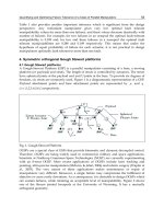
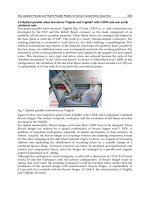
Fig. 1. Parallel kinematics for milling machines
For parallel kinematics machines with reduced number of degrees of freedom kinematics
and singularity analyses can be solved to obtain algebraic expressions, which are well suited
for an implementation in optimum design problems.
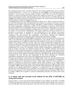
Fig. 2. Benefits of Parallel Kinematics Machines
High dynamical performance is achieved due to the low moved masses. Due to the closed
kinematics the movements of parallel kinematics machines are vibration free for which the
accuracy is improved. Finally, the modular concept allows a cost-effective production of the
mechanical parts.
In this chapter, the optimization workspace index is defined as the measure to evaluate the
performance of two degree of freedom Parallel Kinematics Machines. Another important
contribution is the optimal dimensioning of the two degree-of-freedom Parallel Kinematics
Machines of type Bipod and Biglide for the largest workspace using optimization based on
Genetic Algorithms.
Optimal Design of Parallel Kinematics Machines with 2 Degrees of Freedom
297
2. Objective functions used for optimization of machine tools with parallel
kinematics
One of the main influential factors on the performance of a machine tool with parallel
kinematics is its structural configuration. The performance of a machine tool with parallel
kinematics can be evaluated by its kinematic, static and dynamic properties. Optimal design
is one of the most important issues in the development of a parallel machine tool. Two
issues are involved in the optimal design: performance evaluation and dimensional
synthesis. The latter one is one of the most difficult issues in this field. In the optimum
design process, several criteria could be involved for a design purpose, such as workspace,
singularity, dexterity, accuracy, stiffness, and conditioning index.
After its choice, the next step on the machine tool with parallel kinematics design should be
to establish its dimensions. Usually this dimensioning task involves the choice of a set of
parameters that define the mechanical structure of the machine tool. The parameter values
should be chosen in a way to optimize some performance criteria, dependent upon the
foreseen application.
The optimization of machine tools with parallel kinematics can be based on the following
objectives functions:
• workspace,
• the overall size of the machine tool,
• kinematic transmission of forces and velocities,
• stiffness,
• acceleration capabilities,
• dexterity,
• accuracy,
• the singular configurations,
• isotropy.
In the design process we want to determine the design parameters so that the parallel
kinematics machine fulfills a set of constraints. These constraints may be extremely different
but we can mention:
• workspace requirement,
• maximum accuracy over the workspace for a given accuracy of the sensors,
• maximal stiffness of the Parallel Kinematics Machines in some direction,
• minimum articular forces for a given load,
• maximum velocities or accelerations for given actuator velocities and accelerations.
Determination of the architecture and size of a mechanism is an important issue in the
mechanism design. Several objectives are contradictory to each other. An optimization with
only one objective runs into unusable solutions for all other objectives. Unfortunately, any
change that improves one performance will usually deteriorate the other. This trade-off
occurs with almost every design and this inevitable generates the problem of design
optimization. Only a multiobjective approach will result in practical solutions for machine
tool applications.
The classical methods of design optimization, such as iterative methods, suffer from
difficulties in dealing with this problem. Firstly, optimization problems can take many
iterations to converge and can be sensitive to numerical problems such as truncation and
round-off error in the calculation. Secondly, most optimization problems depend on initial
Parallel Manipulators, Towards New Applications
298
guesses, and identification of the global minimum is not guaranteed. Therefore, the relation
between the design parameters and objective function is difficult to know, thus making it
hard to obtain the most optimal design parameters of the mechanism. Also, it’s rather
difficult to investigate the relations between performance criteria and link lengths of all
mechanisms. So, it’s important to develop a useful optimization approach that can express
the relations between performance criteria and link lengths.
2.1 Workspace
The workspace of a robot is defined as the set of all end-effector configurations which can be
reached by some choice of joint coordinates. As the reachable locations of an end-effector are
dependent on its orientation, a complete representation of the workspace should be
embedded in a 6-dimensional workspace for which there is no possible graphical
illustration; only subsets of the workspace may therefore be represented.
There are different types of workspaces namely constant orientation workspace, maximal
workspace or reachable workspace, inclusive orientation workspace, total orientation
workspace, and dextrous workspace. The constant orientation workspace is the set of
locations of the moving platform that may be reached when the orientation is fixed. The
maximal workspace or reachable workspace is defined as the set of locations of the end-
effector that may be reached with at least one orientation of the platform. The inclusive
orientation workspace is the set of locations that may be reached with at least one
orientation among a set defined by ranges on the orientation parameters. The set of locations
of the end-effector that may be reached with all the orientations among a set defined by
ranges on the orientations on the orientation parameters constitute the total orientation
workspace. The dextrous workspace is defined as the set of locations for which all
orientations are possible. The dextrous workspace is a special case of the total orientation
workspace, the ranges for the rotation angles (the three angles that define the orientation of
the end-effector) being [0,2π].
In the literature, various methods to determine workspace of a parallel robot have been
proposed using geometric or numerical approaches. Early investigations of robot workspace
were reported by (Gosselin, 1990), (Merlet, 1005), (Kumar & Waldron, 1981), (Tsai and Soni,
1981), (Gupta & Roth, 1982), (Sugimoto & Duffy, 1982), (Gupta, 1986), and (Davidson &
Hunt, 1987). The consideration of joint limits in the study of the robot workspaces was
presented by (Delmas & Bidard, 1995). Other works that have dealt with robot workspace
are reported by (Agrawal, 1990), (Gosselin & Angeles, 1990), (Cecarelli, 1995). (Agrawal,
1991) determined the workspace of in-parallel manipulator system using a different concept
namely, when a point is at its workspace boundary, it does not have a velocity component
along the outward normal to the boundary. Configurations are determined in which the
velocity of the end-effector satisfies this property. (Pernkopf & Husty, 2005) presented an
algorithm to compute the reachable workspace of a spatial Stewart Gough-Platform with
planar base and platform (SGPP) taking into account active and passive joint limits. Stan
(Stan, 2003) presented a genetic algorithm approach for multi-criteria optimization of PKM
(Parallel Kinematics Machines). Most of the numerical methods to determine workspace of
parallel manipulators rest on the discretization of the pose parameters in order to determine
the workspace boundary (Cleary & Arai, 1991), (Ferraresi et al., 1995). In the discretization
approach, the workspace is covered by a regularly arranged grid in either Cartesian or polar
form of nodes. Each node is then examined to see whether it belongs to the workspace. The
accuracy of the boundary depends upon the sampling step that is used to create the grid.
Optimal Design of Parallel Kinematics Machines with 2 Degrees of Freedom
299
The computation time grows exponentially with the sampling step. Hence it puts a limit on
the accuracy. Moreover, problems may occur when the workspace possesses singular
configurations. Other authors proposed to determine the workspace by using optimization
methods (Stan, 2003). Numerical methods for determining the workspace of the parallel
robots have been developed in the recent years. Exact computation of the workspace and its
boundary is of significant importance because of its impact on robot design, robot placement
in an environment, and robot dexterity.
Masory, who used the discretisation method (Masory & Wang, 1995), presented interesting
results for the Stewart-Gough type parallel manipulator:
• The mechanical limits on the passive joints play an important role on the volume of
the workspace. For ball and socket joints with given rotation ability, the volume of
the workspace is maximal if the main axes of the joints have the same directions as
the links when the robot is in its nominal position.
• The workspace volume is roughly proportional to the cube of the stroke of the
actuators.
• The workspace volume is not very sensitive to the layout of the joints on the
platforms, even though it is maximal when the two platforms have the same
dimension (in this case, the robot is in a singular configuration in its nominal
position).
Even though powerful three-dimensional Computer Aided Design and Dynamic Analysis
software packages such as Pro/ENGINEER, IDEAS, ADAMS and Working Model 3-D are
now being used, they cannot provide important visual and realistic workspace information
for the proposed design of a parallel robot. In addition, there is a great need for developing
methodologies and techniques that will allow fast determination of workspace of a parallel
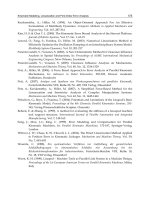
robot. A general numerical evaluation of the workspace can be deduced by formulating a
suitable binary representation of a cross-section in the taskspace. A cross-section can be
obtained with a suitable scan of the computed reachable positions and orientations p, once
the forward kinematic problem has been solved to give p as function of the kinematic input
joint variables q. A binary matrix P
ij
can be defined in the cross-section plane for a
crosssection of the workspace as follows: if the (i, j) grid pixel includes a reachable point,
then P
ij
= 1; otherwise P
ij
= 0, as shown in Fig. 3. Equations (1)-(4) for determining the
workspace of a robot by discretization method can be found in Ref. (Ottaviano et al., 2002).
Then is computed i and j:
⎥
⎦
⎤
⎢
⎣
⎡
Δ+
=
x
xx
i
⎥
⎦
⎤
⎢
⎣
⎡
Δ+
=
y
yy
j
(1)
where i and j are computed as integer numbers. Therefore, the binary mapping for a
workspace cross-section can be given as:
⎩
⎨
⎧
∈
∉
=
)(1
)(0
HWPif
HWPif
P
ij
ij
ij
(2)
where W(H) indicates workspace region;
∈
stands for “belonging to” and ∉is for “not
belonging to”.
Parallel Manipulators, Towards New Applications
300
Fig. 3. The general scheme for binary representation and evaluation of robot workspace
In addition, the proposed binary representation is useful for a numerical evaluation of the
position workspace by computing the sections areas A as:
()
∑∑
==
ΔΔ=
max max
11
i
i
j
j
ij
yxPA
(3)
This numerical approximation of the workspace area has been used for the optimum design
purposes.
2.2 Kinematics accuracy
The kinematics accuracy is a key factor for the design and application of the machine tools
with parallel kinematics. But the research of the accuracy is still in initial stage because of
the various structures and the nonlinear errors of the parallel kinematics machine tools.
To analyze the sensitiveness of the structural error is one of the directions for the research of
structural accuracy. An approach was introducing a dimensionless factor of sensitiveness
for every leg of the structure. Other approach includes the use of the value of Jacobian
matrix as sensitivity index for the whole legs or the use of condition number of Jacobian
matrix as a quantity index to describe the error sensitivity of the whole system.
2.3 Stiffness
Stiffness describes the ratio “deformation displacement to deformation force” (static
stiffness). In case of dynamic loads this ratio (dynamic stiffness) depends on the exciting
frequencies and comes to its most unfavorable (smallest) value at resonance (Hesselbach et
al., 2003). In structural mechanics deformation displacement and deformation force are
represented by vectors and the stiffness is expressed by the stiffness matrix K.
2.4 Singular configurations
Because singularity leads to a loss of the controllability and degradation of the natural
stiffness of manipulators, the analysis of Parallel Kinematics Machines has drawn
considerable attention. This property has attracted the attention of several researchers
because it represents a crucial issue in the context of analysis and design. Most Parallel
Kinematics Machines suffer from the presence of singular configurations in their workspace
Optimal Design of Parallel Kinematics Machines with 2 Degrees of Freedom
301
that limit the machine performances. The singular configurations (also called singularities)
of a Parallel Kinematics Machine may appear inside the workspace or at its boundaries.
There are two main types of singularities (Gosselin & Angeles, 1990). A configuration where
a finite tool velocity requires infinite joint rates is called a serial singularity or a type 1
singularity. A configuration where the tool cannot resist any effort and in turn, becomes
uncontrollable is called a parallel singularity or type 2 singularity. Parallel singularities are
particularly undesirable because they cause the following problems:
• a high increase of forces in joints and links, that may damage the structure,
• a decrease of the mechanism stiffness that can lead to uncontrolled motions of the
tool though actuated joints are locked.
Thus, kinematics singularities have been considered for the formulated optimum design of
the Parallel Kinematics Machines.
2.5 Dexterity
Dexterity has been considered important because it is a measure of a manipulator’s ability to
arbitrarily change its position and orientation or to apply forces and torques in arbitrary
direction. Many researchers have performed design optimization focusing on the dexterity
of parallel kinematics by minimization of the condition number of the Jacobian matrix. In
regards to the PKM’s dexterity, the condition number ρ, given by ρ=σ
max
/σ
min
where σ
max
and σ
min
are the largest and smallest singular values of the Jacobian matrix J.
2.6 Manipulability
The determinant of the Jacobian matrix J, det(J), is proportional to the volume of the hyper
ellipsoid. The condition number represents the sphericity of the hyper ellipsoid. The
manipulability measure w, given by
()
T
JJdetw =
was defined to describe the ability of
machine tool with parallel structure to change its position and direction in its workspace.
3. Two DOF Parallel Kinematics Machines
3.1 Geometrical description of the Parallel Kinematics Machines
A planar Parallel Kinematics Machines is formed when two or more planar kinematic chains
act together on a common rigid platform. The most common planar parallel architecture is
composed of two RP
R chains (Fig. 4), where the notation RPR denotes the planar chain
made up of a revolute joint, a prismatic joint, and a second revolute joint in series. Another
common architecture is P
RRRP (Fig. 5). Two general planar Parallel Kinematics Machines
with two degrees of freedom activated by prismatic joints are shown in Fig. 4 and Fig. 5.
There are a wide range of parallel robots that have been developed but they can be divided
into two main groups:
• Type 1) Parallel Kinematics Machine with variable length struts,
• Type 2) Parallel Kinematics Machine with constant length struts.
Since mobility of these Parallel Kinematics Machines is two, two actuators are required to
control these Parallel Kinematics Machines. For simplicity, the origin of the fixed base frame
{B} is located at base joint A with its x-axis towards base joint B, and the origin of the
moving frame {M} is located in TCP, as shown in Fig. 7. The distance between two base
joints is b. The position of the moving frame {M} in the base frame {B} is x=(x
P
, y
P
)
T
and the
actuated joint variables are represented by q=(q
1
, q
2
)
T
.
Parallel Manipulators, Towards New Applications
302
Fig. 4. Variable length struts Parallel Kinematics Machine
Fig. 5. Constant length struts Parallel Kinematics Machine
3.2 Kinematic analysis of the Parallel Kinematics Machines
PKM kinematics deal with the study of the PKM motion as constrained by the geometry of
the links. Typically, the study of the PKMs kinematics is divided into two parts, inverse
kinematics and forward (or direct) kinematics. The inverse kinematics problem involves a
known pose (position and orientation) of the output platform of the PKM to a set of input
joint variables that will achieve that pose. The forward kinematics problem involves the
mapping from a known set of input joint variables to a pose of the moving platform that
results from those given inputs. However, the inverse and forward kinematics problems of
our PKMs can be described in closed form.
Optimal Design of Parallel Kinematics Machines with 2 Degrees of Freedom
303
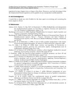
Fig. 6. The general kinematic scheme of a PRRRP Parallel Kinematics Machine
Fig. 7. The general kinematic scheme of a RPRPR Parallel Kinematics Machine
The kinematics relation between x and q of these 2 DOF Parallel Kinematics Machines can
be expressed solving the following equation:
f(x, q)=0 (4)
Then the inverse kinematics problem of the PKM from Fig. 6 can be solved by writing the
following equations:
2
1
2
21
)Lx(Lyq
pP
−−±=
(5)
2
1
2
22
)( LxLyq
pP
+−±=
Parallel Manipulators, Towards New Applications
304
Then the inverse kinematics problem of the PKM from Fig. 7 can be solved by writing the
following equations:
22
1 PP
yxq +=
(6)
22
2
)(
PP
yxbq +−=
The TCP position can be calculated by using inverted transformation, from (6), thus the
direct kinematics of the PKM can be described as:
b
qbq
x
P
⋅
−+
=
2
2
2
22
1
(7)
22
1 PP
xqy −=
where the values of the x
p
, y
P
can be easily determined.
The forward and the inverse kinematics problems were solved under the MATLAB
environment and it contains a user friendly graphical interface. The user can visualize the
different solutions and the different geometric parameters of the PKM can be modified to
investigate their effect on the kinematics of the PKM. This graphical user interface can be a
valuable and effective tool for the workspace analysis and the kinematics of the PKM. The
designer can enhance the performance of his design using the results given by the presented
graphical user interface.
The Matlab-based program is written to compute the forward and inverse kinematics of the
PKM with 2 degrees of freedom. It consists of several MATLAB scripts and functions used
for workspace analysis and kinematics of the PKM. A friendly user interface was developed
using the MATLAB-GUI (graphical user interface). Several dialog boxes guide the user
through the complete process.
Fig. 8. Graphical User Interface (GUI) for solving inverse kinematics of the 2 DOF planar
Parallel Kinematics Machine of type Bipod in MATLAB environment.
Optimal Design of Parallel Kinematics Machines with 2 Degrees of Freedom
305
The user can modify the geometry of the 2 DOF PKM. The program visualizes the
corresponding kinematics results with the new inputs.
Fig. 9. Parallel Kinematics Machine configuration for X
P
=25 mm Y
P
=60 mm
Fig. 10. Parallel Kinematics Machine configuration for X
P
=35 mm Y
P
=60 mm
4. Performance evaluation of Parallel Kinematics Machines
4.1 Workspace determination and optimization of the Parallel Kinematics Machines
The workspace is one of the most important kinematics properties of manipulators, even by
practical viewpoint because of its impact on manipulator design and location in a workcell
(Ceccarelli et al., 2005). Workspace is a significant design criterion for describing the
kinematics performance of parallel robots. The planar parallel robots use area to evaluate
the workspace ability. However, is hard to find a general approach for identification of the
Parallel Manipulators, Towards New Applications
306
workspace boundaries of the parallel robots. This is due to the fact that there is not a closed
form solution for the direct kinematics of these parallel robots. That’s why instead of
developing a complex algorithm for identification of the boundaries of the workspace, it’s
developed a general visualization method of the workspace for its analysis and its design.
A general numerical evaluation of the workspace can be deduced by formulating a suitable
binary representation of a cross-section in the taskspace. Other authors proposed to
determine the workspace by using optimization (Stan, 2003). A fundamental characteristic
that must be taken into account in the dimensional design of robot manipulators is the area
of their workspace. It is crucial to calculate the workspace and its boundaries with perfect
precision, because they influence the dimensional design, the manipulator’s positioning in
the work environment, and its dexterity to execute tasks. Because of this, applications
involving these Parallel Kinematics Machines require a detailed analysis and visualization
of the workspace of these PKMs. The algorithm for visualization of workspace needs to be
adaptable in nature, to configure with different dimensions of the parallel robot’s links. The
workspace is discretized into square and equal area sectors. A multi-task search is
performed to determine the exact workspace boundary. Any singular configuration inside
the workspace is found along with its position and dimensions. The area of the workspace is
also computed.
The workspace is the area in the plane case where the tool centre point (TCP) can be
controlled and moved continuously and unobstructed. The workspace is limited by
singularities. At singularity poses it is not possible to establish definite relations between
input and output coordinates. Such poses must be avoided by the control.
The robotics literature contains various indices of performance (Du Plessis & Snyman, 2001)
(Schoenherr & Bemessen, 1998), such as the workspace index W and the general equation is
given in (8). Workspace for this kind of robot may be easily generated by intersection of the
enveloping surfaces and the area can be also computed.
∫
=
W
dWW
(8)
The workspace of the 2 DOF planar PKM of type Bipod is often represented as a region of
the plane, which can be obtained by the reacheable points of the TCP.
Fig. 11. The workspace is the intersection of two enveloping surface of two legs.
The following presents the main factors affecting workspace. For ease of comparison a cubic
working envelope with a common contour length is used together with a machine size that
Optimal Design of Parallel Kinematics Machines with 2 Degrees of Freedom
307
is calculated from the maximum required strut length. Other design specific factors such as
the end-effector size, drive volumes have been neglected for simplification.
The working envelope to machine size using variable length struts is dependent on the
following factors:
1. The length of the extended and retracted actuator (Lmin, Lmax);
2. Limitations due to the joint angle range.
The limiting effect of the joint limits is clearly illustrated in Fig. 12-13.
Fig. 12. Workspace of the Parallel Kinematics Machine with variable length struts
Fig. 13. Workspace of the Parallel Kinematics Machine with constant length struts
In this section, the workspace of the proposed Parallel Kinematics Machines will be
discussed systematically. It’s very important to analyze the area and the shape of workspace
Parallel Manipulators, Towards New Applications
308
for parameters given robot in the context of industrial application. The workspace is
primarily limited by the boundary of solvability of inverse kinematics. Then the workspace
is limited by the reachable extent of drives and joints, occurrence of singularities and by the
link and platform collisions. The PKM mechanisms P
RRRP and RPRPR realize a wide
workspace as well as high-speed. Analysis, visualization of workspace is an important
aspect of performance analysis. A numerical algorithm to generate reachable workspace of
parallel manipulators is introduced.
Fig. 14. The GUI for calculus of workspace for the planar 2 DOF Parallel Kinematics
Machine with variable length struts
Fig. 15. The GUI for calculus of workspace for the planar 2 DOF Parallel Kinematics
Machine with constant length struts
In the followings is presented the workspace analysis of 2 DOF Bipod PKM.
Case I:
Conditions:
bqq
minmin
>+
21
, bq
max
>
1
, bq
max
>
2
a) for y>0
Optimal Design of Parallel Kinematics Machines with 2 Degrees of Freedom
309
Fig. 16. The workspace of the planar 2 DOF Parallel Kinematics Machine is shown as the
shading region.
b) for
+
∞<<∞− y , there exist two regions of the workspace
Fig. 17. The workspace of the planar 2 DOF Parallel Kinematics Machine is shown as the
shading region.
Case II:
Conditions:
bqq
minmin
>+
21
, bq
max
<
1
, bq
max
<
2
a) for y>0
Fig. 18. The workspace of the planar 2 DOF Parallel Kinematics Machine is shown as the
shading region.
Parallel Manipulators, Towards New Applications
310
b) for
+
∞<<∞− y , there exist two regions of the workspace
Fig. 19. The workspace of the planar 2 DOF Parallel Kinematics Machine is shown as the
shading region.
Case III:
Conditions:
bqq
minmin
<
+
21
, bq
max
>
1
, bq
max
>
2
Fig. 20. The workspace of the planar 2 DOF Parallel Kinematics Machine is shown as the
shading region.
Case IV:
Conditions:
bqq
minmin
<
+
21
, bq
max
<
1
, bq
max
<
2
Fig. 21. The workspace of the planar 2 DOF Parallel Kinematics Machine is shown as the
shading region.
Optimal Design of Parallel Kinematics Machines with 2 Degrees of Freedom
311
Case V:
Conditions:
bqq
minmin
<
+
21
,
minmax
qbq
21
+
> ,
minmax
qbq
12
+
>
Fig. 22. The workspace of the planar 2 DOF Parallel Kinematics Machine is shown as the
shading region.
Case VI:
Conditions:
bqq
minmin
>
+
21
,
minmax
qbq
21
+
> ,
minmax
qbq
12
+
>
Fig. 23. The workspace of the planar 2 DOF Parallel Kinematics Machine is shown as the
shading region.
Case VII:
Conditions:
bq
min
<
1
, bq
max
<
1
, bq
min
<
2
, bq
max
<
2
, bqq
minmin
<+
21
,
bqq
maxmax
>+
21
Fig. 24. The workspace of the planar 2 DOF Parallel Kinematics Machine is shown as the
shading region.
Parallel Manipulators, Towards New Applications
312
In the followings is presented the workspace analysis of 2 DOF Biglide Parallel Kinematics
Machine.
a) Workspace for the planar 2 DOF Parallel Kinematics Machine, case
mmqq
maxmax
100
21
==
b) Workspace for the planar 2 DOF Parallel Kinematics Machine, case
mmqq
maxmax
200
21
==
c) Workspace for the planar 2 DOF Parallel Kinematics Machine, case
mmqq
maxmax
400
21
==
Fig. 25. Different regions of workspace for Biglide PKM for different lengths of stroke of
actuators
Optimal Design of Parallel Kinematics Machines with 2 Degrees of Freedom
313
4.2 Singularity analysis of the Biglide Parallel Kinematics Machine
Because singularity leads to a loss of the controllability and degradation of the natural
stiffness of manipulators, the analysis of parallel manipulators has drawn considerable
attention. Most parallel robots suffer from the presence of singular configurations in their
workspace that limit the machine performances. Based on the forward and inverse Jacobian
matrix, three cases of singularities of parallel manipulators can be obtained. Singular
configurations should be avoided.
In the followings are presented the singular configurations of 2 DOF Biglide Parallel
Kinematic Machine.
Fig. 26. Singular configuration for the planar 2 DOF Biglide Parallel Kinematic Machine
Fig. 27. Singular configuration for the planar 2 DOF Biglide Parallel Kinematic Machine
Parallel Manipulators, Towards New Applications
314
Fig. 28. Singular configuration for the planar 2 DOF Biglide Parallel Kinematic Machine
4.2 Performance evaluation
Beside workspace which is an important design criterion, transmission quality index is
another important criterion. The transmission quality index couples velocity and force
transmission properties of a parallel robot, i.e. power features (Hesselbach et al., 2004). Its
definition runs:
1
2
−
⋅
=
JJ
I
T (9)
where I is the unity matrix. T is between 0<T<1; T=0 characterizes a singular pose, the
optimal value is T=1 which at the same time stands for isotropy (Stan, 2003).
0
50
100
150
0
50
100
150
0.4
0.5
0.6
0.7
0.8
Übertragungsgüte
MA X=
0.658553
MIN=
0.427955
MWT=
0.503084
0.44
0.46
0.48
0.5
0.52
0.54
0.56
0.58
0.6
0.62
0.64
Fig. 29. Transmission quality index for RPRPR Bipod Parallel Kinematic Machine
Optimal Design of Parallel Kinematics Machines with 2 Degrees of Freedom
315
Fig. 30. Transmission quality index for PRRRP Biglide Parallel Kinematic Machine
As it can be seen from the Fig. 30, the performances of the P
RRRP Biglide Parallel Kinematic
Machine are constant along y-axis. On every y section of such workspace, the performance
of the robot can be the same.
5. Optimal design of 2 DOF Parallel Kinematics Machines
5.1 Optimization results for RPRPR Parallel Kinematic Machine
The design of the PKM can be made based on any particular criterion. The chapter presents
a genetic algorithm approach for workspace optimization of Bipod Parallel Kinematic
Machine. For simplicity of the optimization calculus a symmetric design of the structure was
chosen.
In order to choose the PKM’s dimensions b, q
1min
, q
1max
, q
2min
, q
2max
, we need to define a
performance index to be maximized. The chosen performance index is W (workspace) and T
(transmission quality index).
An objective function is defined and used in optimization. It is noted as in Eq. (8), and
corresponds to the optimal workspace and transmission quality index. We can formalize our
design optimization problem as the following:
ObjFun=W+T (10)
Optimization problem is formulated as follows: the objective is to evaluate optimal link
lengths which maximize Eq. (10). The design variables or the optimization factor is the ratios
of the minimum link lengths to the base link length b, and they are defined by:
q
1min
/b (11)
Parallel Manipulators, Towards New Applications
316
Constraints to the design variables are:
0,52<q
1min
/b<1,35 (12)
q
1min
=q
2min
, q
1max
=q
2max
, q
1max
=1,6q
1min
, q
2max
=1,6q
2min
(13)
Fig. 31. Flowchart of the optimization Algorithm with GAOT (Genetic Algorithm
Optimization Toolbox)
For this example the lower limit of the constraint was chosen to fulfill the condition q
1min
≥b/2
that means the minimum stroke of the actuators to have a value greater than the half of the
distance between them in order to have a workspace only in the upper region. For simplicity
of the optimization calculus the upper bound was chosen q
1min
≤1,35b.
During optimization process using genetic algorithm it was used the following GA
parameters, presented in Table 1.
Generations 100
Crossover rate 0.08
Mutation rate 0.005
Population 50
Table 1. GA Parameters
Researchers have used genetic algorithms, based on the evolutionary principle of natural
chromosomes, in attempting to optimize the design parallel kinematics. Kirchner and
Neugebaur (Kirchner & Neugebaur, 2000), emphasize that a parallel manipulator machine
tool cannot be optimized by considering a single performance criterion. Also, using a
Optimal Design of Parallel Kinematics Machines with 2 Degrees of Freedom
317
genetic algorithm, they consider a multiple design criteria, such as the “velocity
relationship” between the moving platform and the actuator legs, the influence of actuator
leg errors on the accuracy of the moving platform, actuator forces, stiffness, as well as a
singularity-free workspace.
A genetic algorithm (GA) is used because its robustness and good convergence properties.
The genetic algorithms optimization approach has the clear advantage over conventional
optimization approaches in that it allows a number of solutions to be examined in a single
design cycle.
The traditional methods searches optimal points from point to point, and are easy to fall into
local optimal point. Using a population size of 50, the GA was run for 100 generations. A list
of the best 50 individuals was continually maintained during the execution of the GA,
allowing the final selection of solution to be made from the best structures found by the GA
over all generations.
We performed a kinematic optimization in such a way to maximize the objective function. It
is noticed that optimization result for Bipod when the maximum workspace of the 2 DOF
planar PKM is obtained for
b/q
min
1
=1,35. The used dimensions for the 2 DOF parallel
PKM were: q
1min
=80 mm, q
1max
=130 mm, q
2min
=80 mm, q
2max
=130 mm, b=60 mm. Maximum
workspace of the Parallel Kinematics Machine with 2 degrees of freedom was found to be
W= 4693,33 mm
2
.
If an elitist GA is used, the best individual of the previous generation is kept and compared
to the best individual of the new one. If the performance of the previous generation’s best
individual is found to be superior, it is passed on to the next generation instead of the
current best individual.
There have been obtained different values of the parameter optimization (q
1
/b) for different
objective functions. The following table presents the results of optimization for different
goal functions. W
1
and W
2
are the weight factors.
Method GAOT Toolbox MATLAB
Z=W
1
·T+W
2
·W, W
1
=0,7
and W
2
=0,3
q
1
/b = 0.92
Z=W1·T+W2·W, W
1
=0,3
and W
2
=0,7
q
1
/b= 1.13
Z= W
1
·T,
W
1
=1 and W
2
=0
q
1
/b=0.71
Goal functions
Z=W
2
·W,
W
1
=0 and W
2
=1
q
1
/b=1.3
Table 2. Results of Optimization for Different Goal Functions
The results show that GA can determine the architectural parameters of the robot that
provide an optimized workspace. Since the workspace of a parallel robot is far from being
intuitive, the method developed should be very useful as a design tool.
However, in practice, optimization of the robot geometrical parameters should not be
performed only in terms of workspace maximization. Some parts of the workspace are more
useful considering a specific application. Indeed, the advantage of a bigger workspace can