Autodesk Revit Architecture 2011 No Experience Required - part 4 pdf
Bạn đang xem bản rút gọn của tài liệu. Xem và tải ngay bản đầy đủ của tài liệu tại đây (749.73 KB, 10 trang )
Chapter 1 • The Revit World
4
4. In the upper-left corner of the Revit window, you will see a big purple
R. Click the purple R and choose New
➢ Project.
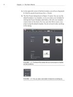
5. The New Project dialog shown in Figure 1.5 opens. You can use the
default template or no template, or you can create a new template by
clicking the Project Template radio button. (We will cover template
creation later in the book.) For now, just click OK to create a new
project using the default template. You do not need to alter anything
in this dialog.
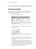
FIGURE 1.3 The Recent Files window lists any recent projects or families
you have worked on.
FIGURE 1.4 You can create a new model or browse for an existing one.
The Revit Architecture Interface
5
FIGURE 1.5 The New Project dialog allows you to start a new project using
a preexisting template file, or you can create a new template file.
Now that the task of physically opening the application is out of the way, we can
delve into Revit. At first, you will notice many differences between Revit and CAD.
Some of these differences may be off-putting, while others will make you say “I
wish AutoCAD did that.” Either way, you will have to adjust to a new workflow.
The Revit Workflow
Revit has a certain feel that you AutoCAD converts will need to get a grasp on.
This new workflow may be easy for some to adapt to, whereas others will find it
excruciatingly foreign. (To be honest, I found the latter to be the case at first.)
Either way, it is a simple concept. You just need to slow down a bit from your
AutoCAD habits.
Executing a command in Revit is a three-step process:
1. At the top of the Revit window is the Ribbon, and built into the Ribbon
is a series of tabs. Each tab contains a panel. This Ribbon will be your
Revit launch pad! Speaking of launch pad, click the Wall button on the
Home tab, as shown in Figure 1.6.
2. After you click the Wall button, notice that Revit adds an additional tab
to the Ribbon, with options specific to the command you are running,
as shown in Figure 1.7. This tab allows you to make different choices
based on the placement of a wall. You may also notice that Revit places
an additional Options bar below the Ribbon for more choices.
FIGURE 1.6 The Ribbon is the backbone of Revit Architecture.
Chapter 1 • The Revit World
6
FIGURE 1.7 The Options bar replaces the command prompt from AutoCAD.
Microstation users will be more familiar with this method.
3. After you make your choices from the Ribbon and the Options bar,
you can place the object into the view window. This is the large draw-
ing area that takes up two thirds of the Revit interface. To place the
wall, simply pick a point in the window and move your pointer. The
wall starts to form. You can press the Esc key to exit the command.
Using Revit is not generally as easy as this, but keep in mind this basic three-
step process:
1. Start a command.
2. Choose an option from the temporary tab that appears.
3. Place the item in the view window.
Revit appears to offer a fraction of the choices and functionality that AutoCAD or
any drafting program offers. This is true in a way. Revit does offer fewer choices to
start a command, but how many choices does an architect or architectural designer
need? Revit keeps its functionality focused on architecture and construction. Revit
gets its robust performance from the dynamic capabilities of the application during
the placement of the items and the functionality of the objects after you place them
in the model. Never judge a book by its cover — unless, of course, it is the book you
are reading right now.
Let’s keep going with the main focus of the Revit interface: the Ribbon.
You will be using the Ribbon exclusively within Revit.
Using the Ribbon
You will use the Ribbon for the majority of the commands you execute in Revit.
As you can see, you don’t have much choice to do otherwise. However, this is good
because it narrows your attention to what is right in front of you. When you click
You will hear this
throughout the book:
always remember to
look at your options.
With no command
prompt, the Options
bar will be one of
your few guides.
The Revit Architecture Interface
7
an icon on the Ribbon, Revit will react to that icon with a new tab, giving you the
specific additional commands and options you need. Revit also keeps the existing
tabs that can help you in the current command, as shown in Figure 1.8. Again, the
focus here is to keep your eyes in one place.
In this book, I will throw a few new terms at you, but you will get familiar
with them quickly. We just discussed the Ribbon, but mostly you will be directed
to choose a tab, and to find a panel on that tab.
To keep the example familiar, when you selected the Wall button, your instruc-
tions will read: “On the Build panel of the Home tab, click the Wall button.”
FIGURE 1.8 The Ribbon breakdown
Wh a t ’s th a t to o l b a r a b o v e t h e ri b b o n ?
This toolbar is called the Quick Access toolbar. It is filled with some popular
commands. One special function of this toolbar is the cursor icon. You use
this icon when you wish to terminate a command. If you want to add to this
toolbar, simply right-click any icon and select Add To Quick Access Toolbar.
To the left of this toolbar is the Revit Home button. Clicking this button gives
you access to more Revit functions that will be covered later in the book.
Chapter 1 • The Revit World
8
Now that you can see how the ribbons and the tabs flow together, let’s take a
look at another feature within the Ribbon panels that allows you to reach beyond
the immediate Revit interface.
The Properties Interface
When you click the Wall button, an entirely new set of commands appears. This
new set of commands combines your basic Modify commands with an additional
tab specific to your immediate process. In this case that process is adding a wall.
You will also notice that a Properties dialog appears to the left of the screen. If
you do not see the Properties dialog, click the Properties icon that is displayed in
Figure 1.9. In the Properties dialog is a picture of the wall you are about to place.
If you click on this picture, Revit will display all the walls that are available within
the model. This display is called the Change Element Type menu (see Figure 1.10).
FIGURE 1.9 Click the Properties button to display the Properties dialog. Typically the
dialog is shown by default.
FIGURE 1.10 The Properties button gives you access to many variables associated with
the item you are adding to the model.
The objective of the next exercise is to start placing walls into the model:
1. Open Revit Architecture using the default template.
The Revit Architecture Interface
9
2. On the Home tab, click the Wall button.
3. In the Properties dialog, select Exterior - Brick and CMU on MTL.Stud.
Element Properties
Hidden within the Options bar is a single button. There are two different sets of
properties you will deal with in Revit: Instance Properties and Type Properties.
Instance Properties will be available immediately in the Properties dialog when
you place, or select, an item. If you make a change to an element property, the
only items that are affected in the model are the items you have selected.
The Properties Dialog
The Properties dialog is new to Revit Architecture 2011. As just mentioned, the
Properties dialog will display the Instance Properties of the item you have selected.
If no item is selected, this dialog will display the View Properties.
In addition to accessing the Instance Properties, you can click the Edit Type
button to open a dialog displaying the Type Properties of the selected item (see
Figure 1.11). By making a modification here, you will change every occurrence
of that item in the entire model.
FIGURE 1.11 The Type Properties dialog gives you access to the parameters associated
with the element you have selected.
Let’s take a closer look at the two categories of Element Properties in Revit.
Chapter 1 • The Revit World
10
Instance Properties
The items that you can edit immediately are called parameters, or Instance
Properties. These parameters will change only the object being added to the
model at this time. Also, if you select an item that has already been placed in the
model, the parameters you see immediately in the Instance Properties dialog will
change only that item you have selected. This makes sense — not all items are
built equally in the real world. Figure 1.12 illustrates the Instance Properties of a
typical wall.
Type Properties
The Type Properties (see Figure 1.13), when edited, will alter every item of that
type in the entire model. To access the Type Properties, click the Edit Type but-
ton in the Properties dialog, as Figure 1.14 shows.
FIGURE 1.12 The Instance Properties will change only the currently placed item or the
currently selected item.
At this point, you have two choices. You can either make a new wall type
(leaving this specific wall unmodified) by clicking the Duplicate button, or you
can start editing the wall’s Type Properties, as shown in Figure 1.15.
WARNING
I cannot stress enough that if you start modifying Type
Properties without duplicating the type, you need to do so in a very deliberate
manner. You can easily affect the model in unintended ways. We will discuss the
specics of all the wall’s Type Properties in Chapter 16, “Advanced Wall Topics.”
The Revit Architecture Interface
11
FIGURE 1.13 The Type Properties, when modified, will alter every occurrence of this
specific wall in the entire model.
FIGURE 1.14 The Edit Type button allows you to access the Type Properties.
Chapter 1 • The Revit World
12
FIGURE 1.15 The Type Properties are used to modify the wall system’s global settings.
Click the Preview button at the bottom of the dialog to see the image that is displayed.
Now that you have gained experience with the Type Properties dialog, it is
time to go back and study the Options bar as it pertains to placing a wall:
1. Since we are only exploring the Element Properties, click the Cancel
button to return to the model.
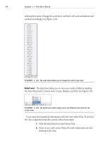
2. Back in the Options bar, find the Location Line menu. Through this
menu you can set the wall justification. Select Finish Face: Exterior
(see Figure 1.16).
3. On the Options bar, be sure the Chain checkbox is selected, as
Figure 1.16 shows. This will allow you to draw the walls continuously.
4. In the Draw panel, there is a series of sketch options. Because this
specific wall is straight, make sure the Line button is selected, as
shown in Figure 1.17.
Get used to studying the Ribbon and the Options bars — they will be your
crutch as you start using Revit Architecture! Of course, at some point you need
to physically start placing items in the model. This is where the view window
comes into play.
The Revit Architecture Interface
13
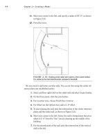
FIGURE 1.16 By selecting Finish Face: Exterior, you know the wall will be dimensioned
from the outside finish.
FIGURE 1.17 You can draw any shape you need.
The View Window
To put it simply, “the big white area where the objects go” is the view window. As
a result of your actions, this area will become populated with your model. Notice
the background is white — this is because the sheets you plot on are white. In
Revit, what you see is what you get … literally. In Revit, you aren’t counting on
color #5, which is blue, for example, to be a specific line width when you plot.
You can immediately see the thickness that all your “lines” will be before you
plot (see Figure 1.18). What a novel idea.