Autodesk Revit Architecture 2011 No Experience Required - part 5 docx
Bạn đang xem bản rút gọn của tài liệu. Xem và tải ngay bản đầy đủ của tài liệu tại đây (453.74 KB, 10 trang )
Chapter 1 • The Revit World
14
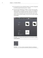
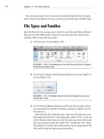
FIGURE 1.18 The view window collects the results of your actions.
To continue placing some walls in the model, keep going with the exercise.
(If you have not been following along, you can start by clicking the Wall button
on the Home tab. In the Properties dialog box, select Exterior - Brick and CMU
on MTL.Stud. Make sure that the wall is justified to the finish face exterior.) You
may now proceed:
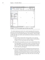
1. With the Wall command still running and the correct wall type
selected, position your cursor in a similar location to the illustration
in Figure 1.19. Now, pick a point in the view window.
2. With the first point picked, move your cursor to the left. Notice that a
two things happen: the wall seems to snap in a horizontal plane, and
a blue dashed line apparently locks the horizontal position. In Revit,
there is no “Ortho.” Revit will align the typical compass increments
to 0, 90, 180, 270, and 45 degrees.
3. Also notice the blue dimension extending from the first point to the
last point. Although dimensions cannot be typed over, this type of
dimension is a temporary dimension for you to use as you place items.
Type 100, and press the Enter key. (Notice you did not need to type the
foot mark (
′). Revit thinks in terms of feet. The wall is now 100′ long
(see Figure 1.19).
The Revit Architecture Interface
15
FIGURE 1.19 The procedure for drawing a wall in Revit Architecture
4. With the Wall command still running, move your cursor straight up
from the endpoint of your 100
′-long wall. Look at Figure 1.20.
5. Type 80 and hit Enter. You now have two walls.
6. Move your cursor to the right until you “run into” another blue
alignment line. Notice that your temporary dimension says 100′–0″.
Revit understands symmetry. After you see this alignment line, and
the temporary dimension says 100
′–0″, pick this point.
7. Move your cursor straight down and type 16, and hit Enter.
8. Move your cursor to the right and type 16, and hit Enter.
9. Press the Esc key.
Do your walls look like Figure 1.21? If not, try it again. You need to be com-
fortable with this procedure (as much as possible).
Chapter 1 • The Revit World
16
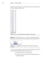
FIGURE 1.20 How Revit Architecture works is evident in this procedure.
FIGURE 1.21 Working with Revit starts with the ability to work with the view window,
and learning the quirks and feel of the interface.
To get used to the Revit flow, always remember these three steps:
1. Start a command.
2. Focus on your options.
3. Move to the view window, and add the elements to the model.
The Revit Architecture Interface
17
If you start a command, then focus immediately on the view, you will be sit-
ting there wondering what to do next. Do not forget to check your Options bar
and the appropriate ribbon tab.
Let’s keep going and close this building by using a few familiar commands. If
you have never drafted on a computer before, don’t worry. These commands are
simple. The easiest but most important topic is simply how to select an object.
Object Selection
Revit has a few similarities to AutoCAD and MicroStation. One of those similarities
is the ability to perform simple object selection and to execute common modify
commands. For this example, we will mirror the two 16
′
–0
″
L-shaped walls to the
bottom of the building:
1. Type ZA (zoom all).
2. Near the two 16
′–0″ L-shaped walls, pick (left-click) and hold down
the left mouse button when the cursor is at a point to the left of the
walls but above the long, 100
′–0″ horizontal wall.
3. You will see a window start to form. Run that selection window past the
two walls. After you highlight the walls, as illustrated in Figure 1.22, let
go of the mouse button, and you have selected the walls.
FIGURE 1.22 Using a crossing window to select two walls
There are two ways to select an object: by using a crossing window or by using
a box. Each approach plays an important role in how you select items in a model.
Crossing Windows
A crossing window describes an object selection method in which the window
being placed only needs to cross through the objects in order to select them. A
crossing window will always start from the right and end to the left. The cross-
ing window, when being placed, is represented by a dashed-line composition (see
Figure 1.22).
Chapter 1 • The Revit World
18
Boxes
A box is an object selection method that will only select the items that are 100
percent inside the window being placed. This method is useful when you want
to select only specific items while passing through larger objects that you may
not want in the selection set. A box always starts from the left and works to the
right. The line type for a selection window is a continuous line (see Figure 1.23).
FIGURE 1.23 To select only objects that are surrounded by the window, select a box.
This will leave out any item that may only be partially within the box.
Now that you have experience selecting items, you can execute some basic modify
commands. Let’s begin with mirroring, one of the most popular modify commands.
Modifying and Mirroring
You will find that Revit Architecture requires that you select items first and then
execute a command. This is true for most action items, and is certainly true for
every command on the Modify toolbar.
1. Make sure only the two 16
′–0″ walls are selected.
2. Once the walls are selected, you will see the Modify Walls tab appear.
On the Modify panel, click the Mirror Draw Axis button, as shown in
Figure 1.24.
FIGURE 1.24 The Ribbon adds the appropriate commands.
The Revit Architecture Interface
19
3. Your cursor will change to a crosshair with the mirror icon illustrating
that you are ready to draw a mirror plane, as shown in Figure 1.25.
FIGURE 1.25
There are options you must choose for every command in Revit.
4. Make sure the Copy checkbox is selected (see Figure 1.25).
5. Hover your cursor over the inside face of the 80
′
–0
″
-long vertical wall
until you get reach the midpoint. Revit will display a triangular icon,
indicating that you have found the midpoint of the wall (see Figure 1.26).
FIGURE 1.26
Revit has snaps similar to most CAD applications. In Revit, you
will only get snaps if you choose the draw icon from the Options bar during a command.
6. When the triangular midpoint snap appears, pick this point. After you
pick the point where the triangle appears, you can move your cursor
directly to the right of the wall. You will see an alignment line appear,
Chapter 1 • The Revit World
20
as illustrated in Figure 1.27. When the alignment line appears, you can
pick another point along the path. When you pick the second point, the
walls are mirrored and joined with the south wall (see Figure 1.27).
FIGURE 1.27 Mirroring these walls will involve first, picking the midpoint
of the vertical wall, then second, picking a horizontal point along the plane.
Now that you have some experience mirroring items, it is time to start adding
components to your model by utilizing the items that you placed earlier. If you
having trouble following the process, retry these first few procedures. Rome was
not built in a day. (Well, perhaps if they had Revit, it would have sped things up!)
You want your first few walls to look like Figure 1.28.
FIGURE 1.28 Your building should look like this illustration.
Building on Existing Geometry
Now that you have some geometry to work with and you have some objects placed
in your model, Revit starts to come alive. The benefits of using building information
The Revit Architecture Interface
21
modeling (BIM) will become apparent quickly, as explained later in this chapter. For
example, because Revit knows that walls are walls, you can add identical geometry
to the model by simply selecting an item and telling Revit to create a similar item.
Suppose you want a radial wall of the same exact type as the other walls in the
model. Perform the following steps:
1. Type ZA to zoom the entire screen.
2. Press the Esc key.
3. Select one of the walls in the model — it does not matter which one.
4. Right-click on the wall.
5. Select Create Similar, as shown in Figure 1.29.
NOTE
New to Revit 2011, when you right-click on an item, you can
choose to repeat the last command. You can now also select all items that
are only in the current view.
6. On the Modify | Place Wall tab, click the Start-End-Radius Arc but-
ton, as shown in Figure 1.30.
FIGURE 1.29 You can select any item in Revit and create a similar object
by right-clicking and selecting Create Similar.
7. Again with the Options? Yes. Make sure your Location Line is set to
Finish Face: Exterior.
Chapter 1 • The Revit World
22
FIGURE 1.30 Just because you started the command from the view
window does not mean you do not have to look at your options.
8. With the wheel button on your mouse, zoom into the upper corner
of the building and select the top endpoint of the wall, as shown in
Figure 1.31. The point you are picking is the corner of the heavy lines.
The topmost, thinner line represents a concrete belt course below. If
you are having trouble picking the correct point, don’t be afraid to
zoom into the area by scrolling the mouse wheel.
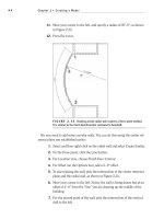
FIGURE 1.31 Select the top corner of the wall to start your new radial wall.
9. Select the opposite, outside corner of the bottom wall. Again, to be
more accurate, you will probably have to zoom into each point as you
are making your picks.
10. Move your cursor to the right until you see the curved wall pause.
You will also see an alignment line and a tangent snap icon appear as
The Revit Architecture Interface
23
well. Revit understands that perhaps you want an arc tangent upon
the two lines you have already placed in your model.
11. Press Esc to terminate the command.
12. When you see the tangent snap icon, choose the third point. Your walls
should look like Figure 1.32.
FIGURE 1.32 The completed exterior walls should look like this illustration.
Just because you have placed a wall in the model does not mean the wall looks
the way you would like. In Revit Architecture, you can do a lot with view control
and how objects are displayed.
View Control and Object Display
Although the earlier procedures are a nice way to add walls to a drawing, they
do not reflect the detail you will need to produce construction documents. Well,
the great thing about Revit is that you have already done everything you need to
do. You can now tell Revit to display the graphics the way you want to see them.
The View Control Bar
At the bottom of the view window, you will see a skinny toolbar (as illustrated in
Figure 1.33). This is the View Control bar. It contains the functions outlined in
the following list:
FIGURE 1.33 The View Control bar controls the graphical view of your model.
Scale The first item on the View Control bar is the scale function. It gets small
mention here, but it is a huge deal. In Revit, you change the scale of a view by