Autodesk Revit Architecture 2011 No Experience Required - part 12 pdf
Bạn đang xem bản rút gọn của tài liệu. Xem và tải ngay bản đầy đủ của tài liệu tại đây (540.61 KB, 10 trang )
Chapter 2 • Creating a Model
84
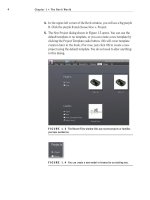
FIGURE 2.65 Adding a door
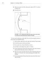
4. Move your cursor over to the south wall near the elevator shaft, as
shown in Figure 2.66. Notice that if your cursor is not within a wall,
you get the “NO” sign. Revit will not allow you to just place a door
into space. A door is considered a hosted family.
5. After you get your cursor positioned approximately where Figure 2.66
shows, move your pointer up and down. Notice the door’s direction
will change. This is typical behavior for a door.
6. Press the spacebar. Notice the door swing will flip direction.
7. Make the door face outward and to the left, as shown in Figure 2.66.
Then pick (left-click) a point on the wall. If you accidentally put it in
wrong, don’t worry—we can fix it. Press Esc.
FIGURE 2.66 Placing a door will always require a host. Remember, you
can press the spacebar to change the orientation, and move your cursor up and
down to flip the direction.
Placing Doors and Windows
85
Notice that when the door is placed, a tag shows up with an automatic num-
ber. In Revit, after you place a door you should go right back and select it. This
will highlight the door and activate a few different options. Follow these steps:
1. Click the Modify button on the left of the Ribbon. This will disengage
you from the Door command.
2. Pick the door you just added to the model. Notice there are blue
temporary dimensions. Let’s make sure these dimensions are going
where we want them.
a. On the Settings panel of the Manage tab, click Additional
Settings
➢ Temporary Dimensions, as shown in Figure 2.67.
FIGURE 2.67 Select Additional Settings ➢ Temporary Dimensions.
b. Make sure that Wall Dimensions are going to Faces and that
Door Dimensions are going to Openings.
c. Click OK.
Chapter 2 • Creating a Model
86
yi k e s, lo o k a t My Wa l l s !
When you place a door or any opening into a compound wall, you need to tell
Revit specifically how to wrap the materials. By default, Revit will stop the brick
and any other finish right at the opening. Obviously this is usually not the case.
The following steps will guide you through wrapping materials at an insert:
1. Select the exterior wall.
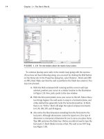
2. In the Properties dialog, click the Edit Type button, as shown here:
3. In the drop-down menu that specifies wrapping at inserts, select Both.
4. Click OK.
Now that we have configured the temporary dimensions the way we need
them, we can start using them to manipulate the placement of our doors:
1. Select the door again.
2. Move the left witness line to the outside face of the CMU wall, as
shown in Figure 2.68.
Placing Doors and Windows
87
3. As you know, in Revit Architecture anything that turns blue can be
edited. Click on the blue dimension that extends from the CMU wall,
drag it to the right of the elevator shaft, and change it to 1
′–0″ (see
Figure 2.69).
FIGURE 2.68 Moving the witness line to a more appropriate location
FIGURE 2.69 Changing the temporary dimension
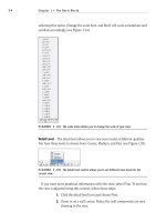
Placing Wall Tags
Notice the tag that shows up? This is an automatic feature of Revit, as is the
tag’s number. Under normal circumstances, Revit will number it incorrectly.
Luckily you can renumber it:
1. Select the door.
2. Pick (left-click) the number in the door tag.
3. Change the number to 101.
4. With the door still selected, notice you have flip arrows as well. If the
door is not in the orientation you see in the previous figures, click
these arrows to flip the door.
5. Mirror this door and its tag about the building’s centerline.
Most items that
are added to the
Revit model can be
selected and flipped
in the same method.
Also, if you select
the items to be
flipped and press the
spacebar, it will have
the same effect.
O
Chapter 2 • Creating a Model
88
Loading Families
It would be nice if the seven doors available in the Revit model were all you
needed. They, of course, are not. Revit, like most other CAD and applications
that use building information modeling, does not load every single component
into the drawing or model. File size is just as much of a concern in Revit as it is
in AutoCAD. If you need a different door, you have to go get it:
1. On the Home tab, click the Door button.
2. On the Modify | Place Door tab, click the Load Family button, as
shown in Figure 2.70.
FIGURE 2.70 Click Load Family on the Mode Panel.
3. Find the Doors directory; navigate to Double-Flush.rfa and click Open.
4. Select Double-Flush: 72″ × 84″ from the Properties panel.
5. Place the double doors in the wall, as shown in Figure 2.71.
FIGURE 2.71 Placing the double doors
6. Mirror the door and tag using the center reference plane.
Normally the doors
will automatically
“nd” the center
of the wall. But to
make sure, you can
type SM. This will
tell Revit that you
want to snap to the
middle.
Placing Doors and Windows
89
7. Add bathroom doors, as shown in Figure 2.72. Use Single-Flush:
36
″ × 84″?
8. Label them accordingly.
9. In the exterior wall that divides the east building from the corridor,
add a Single Raised Panel with Side Lights: 36″ × 84″ door centered
upon the opening.
10. Change the tag to read 100B, as shown in Figure 2.73.
FIGURE 2.72 Adding lavatory doors. You will have to renumber the tags.
FIGURE 2.73 Adding a new corridor door. If this door is not loaded into
your model, you have to click the Load Family button on the Mode panel of the
Modify | Place Door tab.
Chapter 2 • Creating a Model
90
We need to add more doors and interior partitions, but they will be best suited
for Chapter 4 where we can be more accurate. In the meantime, however, let’s
add some simple openings.
Placing Openings in Your Walls
Openings are categorized with doors but need to be added to the model using
the Component command. No, really. It’s true. Follow along:
1. On the Home tab, click Component, as shown in Figure 2.74.
FIGURE 2.74 Clicking Component on the Home tab
2. On the Modify | Place Component tab, click the Load Family button.
3. Browse to the
Doors directory.
4. Find the file called
Opening-Cased.rfa and click Open.
5. Click the Edit Type button in the Properties panel.
6. Click Duplicate in the Type Properties dialog.
7. In the Name dialog, name the opening 84”
×84” then click OK.
8. Under Dimensions, change Width to 7
′–0″.
9. Click OK. Then hit Esc to clear the command.
10. Zoom into the area shown in Figure 2.75, and place an Interior - 6 1/8″
Partition (2-hr) wall as shown. This is the wall you will place the
opening into.
Placing Doors and Windows
91
11. Click Component, and place the opening into the wall as shown in
Figure 2.75.
Figure 2.75 The new opening
Add two more doors, and we are finished with this section:
1. On the Home tab, click Door.
2. In the Properties dialog, pick Double-Flush: 72
″ × 84″.
3. Add the double doors to the ends of the vertical corridor, as shown in
Figure 2.76.
4. Label them as 100C and 100D.
Figure 2.76 Two new corridor doors
Chapter 2 • Creating a Model
92
Again, there are plenty more doors and partitions that we can add to the model,
but they will be added in Chapter 4. Let’s move on to adding some windows!
Adding Windows
Doors, windows, openings… it’s all the same really. Once you have experience
adding one, the other is just as easy!
The objective of the next procedure is to add some windows to the model.
1. On the Home tab, click the Window button, as shown in Figure 2.77.
FIGURE 2.77 Adding a window is the same as adding a door.
2. Select the Fixed: 36″ × 72″ window from the Properties panel.
3. Add the window to the corner of the building, as shown in Figure 2.78.
Be careful with the placement. If your cursor is toward the exterior of
the wall, the window will be orientated correctly.
FIGURE 2.78 Depending on the side of the wall your cursor is on, you can
add a window to the correct orientation.
Placing Doors and Windows
93
4. Add two more windows to the west wall adjacent to the wall you just
put the first window in. Use your temporary dimensions to ensure
you are placing the windows 1
′–0″ from the opening to the wall.
5. Mirror the windows and tags (see Figure 2.79).
FIGURE 2.79 Placing the windows to the corner of the building and
mirroring them
6. Select one of the placed windows. Notice the temporary dimensions
and the flip arrows.
7. Change the tag to read A. (All of the windows are type A.)
8. You will get a warning stating that you are changing a type parameter.
Click OK.
Now that the windows are in place, it is time to investigate how they are built
by taking a look at their properties.
Window Properties
Again, just as with doors and openings, you can check the Element Properties to
tweak the unit even further:
1. Select one of the windows.