Autodesk Revit Architecture 2011 No Experience Required - part 15 ppt
Bạn đang xem bản rút gọn của tài liệu. Xem và tải ngay bản đầy đủ của tài liệu tại đây (508.62 KB, 10 trang )
Chapter 3 • Creating Views
114
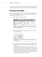
FIGURE 3.30 The final look of the building
Creating Building Sections
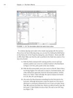
As your model starts to develop, you will begin to see areas that need further
attention. (Certainly the area where the corridor hits the west building needs to
be fixed.) This brings us to a good point. Sections in Revit Architecture, when
placed into the model, not only help us build a set of construction documents,
but also help us to physically work on the model. For example, we need to fix the
east wall of the west wing. We don’t have any good views established that focus
directly on this area. This is the perfect place to add a section!
To begin, open your model, or go to www.sybex.com/go/revit2011ner and
browse to Chapter 3. Open the file called
NER-06.rvt. If you wish, you can use a
project you are working on. You will just need to replace any names and specific
dimensions with ones that are applicable to your project. To add a section and
some cool wall modify commands, follow along:
1. Go to Level 1 and zoom in on the area where the corridor meets the
west wing of the building.
2. On the Create panel of the View tab, select Section, as shown in
Figure 3.31.
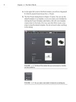
3. A section takes two picks to place into the model. You must first pick
the point for the head; then you must pick a point for the tail. To place
the section as shown in Figure 3.32, first pick a point above the corri-
dor and to the right of the vertical wall.
4. After you pick the first point, move your cursor straight down the view.
When you are positioned directly below the bottom corridor wall, pick
the second point (see Figure 3.32). If the section is facing the wrong
way, that’s fine. We will fix that in a moment.
5. Now that you placed the section, it looks like we need to flip it to face
the wall we intended to modify. Pick the section. You will see a few
blue icons appear. We are interested in the icon that looks like two
Creating Building Sections
115
arrows. This is a flip grip. It is the same thing we saw in the doors and
windows (see Figure 3.33).
FIGURE 3.31 The Section command is found on the Create panel of the
View tab.
FIGURE 3.32 Placing the section into the model
Chapter 3 • Creating Views
116
FIGURE 3.33 After you select the section, you will see the flip grip.
6. When you see the flip grip, pick it. It will flip the section into the cor-
rect direction.
WARNING
We may be jumping ahead here, but here’s a word of
caution: if you cut a section in Revit Architecture, then place detail compo-
nents and draft over the top of that section, you are stuck. Do not flip or move
the section after you have drafted over the top of a section. The results will be
bad. The walls will move, not your linework, leaving you with a mess.
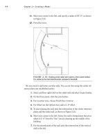
With the section flipped in the correct direction, you will see a
dashed line that forms a box around part of the model, as shown in
Figure 3.34. This forms the view extents of the section. Anything
outside of this box will not be shown.
7. The vertical dashed line (to the left) will have a move arrow. Pick
the move arrow and drag the crop region into an area as shown in
Figure 3.34.
NOTE
If you don’t have the section selected, you need to select it.
You must pick the line of the section, not the bubble. When you pick the
line, the section is selected.
8. With the section still selected, notice you have a small, blue break icon
in the middle of the section (see Figure 3.35). Pick the break line (it is
called the Gaps In Segments icon). The section is now broken, and you
will have grips controlling the ends of the break lines (see Figure 3.35).
Creating Building Sections
117
FIGURE 3.34 You can control how deep into the building you want the section to look.
FIGURE 3.35 Adding a gap in the section. You can move your grips to be
the same as the figure.
9. At each end of the section you will see a blue icon that resembles a
recycle figure. This controls what the section head will display. By
Chapter 3 • Creating Views
118
selecting this “recycle” icon, you can choose to have a section head, a
tail, or nothing. At the tail of the section, cycle through until you get
a section head (see Figure 3.36).
FIGURE 3.36 Cycling through the display choices
With the section cut, it is time to open the view we have created. In the Project
Browser, you will now see a new category called Sections (Building Section). In
this Sections category, you will have a view called Section 1. When you cut the
section, you added a view to the project. This view will carry its own properties
and can be drafted over (see Figure 3.37).
FIGURE 3.37 The Project Browser with the new section
TIP
Be organized. Just because you are using BIM, that does not
negate the need for basic organization. The first thing you should do when
creating a section (or any new view for that matter) is give it a name. If you
don’t, and leave it Section 1, Section 2, Section 3…, you find yourself wast-
ing a lot of time looking for the right view.
Creating Building Sections
119
At this point, you need to name the section and open the view. We can also fix
the gap in the wall while we are at it. Just perform the following steps:
1. In the Project Browser, right-click on Section 1.
2. Choose Rename from the context menu (see Figure 3.38).
3. Change the name of Section 1 to West Corridor Section.
FIGURE 3.38
You can rename the view by right-clicking in the Project Browser.
4. Click OK.
5. Double-click on the West Corridor Section in the Project Browser.
This will open the section. You can see the two corridor walls and the
west wing beyond.
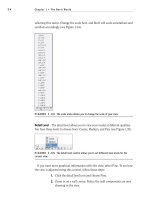
6. You will notice immediately that the level information is running into
the walls. To fix this, simply select the West Parapet level. (Remember:
select the actual line, not the datum head.)
7. Slide the elevation markers to the right, out of the way of the walls
(see Figure 3.39).
8. Repeat the process for Level 1 and Level 2 if necessary. Notice that
when you slide these levels to the right, they will snap into place and
align themselves to the rest of the levels.
Chapter 3 • Creating Views
120
9. Pick the left end of the level lines, and move them to the right as well.
This will get all of the lines out of the way so that you can work on the
section (see Figure 3.40).
FIGURE 3.39 You can adjust the levels by picking and dragging the blue
grip at the intersection of the level line and the datum bubble.
NOTE
Notice that when you are adjusting the levels in the section the
2D icon appears. This means that any adjustments made here will not affect any
other views. In a sectional view, Revit will automatically make the levels 2D. In
an elevation view, however, Revit will make the levels 3D. If you want to make
adjustments in an elevation, it is a good idea to turn these to 2D extents.
10. Also, add some elbows to the elevation markers. There are so many
that the text elements collide with one another.
11. On the View Control bar, select Fine for the detail level, as shown in
Figure 3.40. (Making adjustments like this to a view will become sec-
ond nature to you very soon.)
Creating Building Sections
121
FIGURE 3.40 On the View Control bar, set Fine as the detail level.
Cutting a section is immensely helpful in terms of viewing the model from
any perspective you want. To go even further, when you cut a section you can
also work on your model by modifying any item the section.
Making Building Modifications in a Section
Now that you have a good look at this side of the west wing, it is obvious that
this wall needs to be repaired. In Revit Architecture, you can make a modifica-
tion to a building in any view. This is good and bad. Just remember that every-
thing you do has a downstream effect on the entire model.
To follow along, open your model, or go to www.sybex.com/go/revit2011ner
and browse to Chapter 3. Open the file called
NER-06.rvt if it is not open already.
If you wish, you can use a project you are working on and replace any names and
specific dimensions with ones that are applicable to your project.
The following procedure will guide you through making a modification to a
wall’s profile while in a section view:
1. In the Project Browser, find the West Corridor Section and open it by
double-clicking on the name West Corridor Section (if it is not open
already).
2. In this section, select the east wall of the west wing, as shown in
Figure 3.41.
3. After you select the wall, look to your Modify | Walls tab. There you
will see a button that says Edit Profile, as shown in Figure 3.41. Click
that button.
O
In Revit Architecture,
you can also double-
click on the actual
annotation that refers
to the view you wish
to open. For example,
if you want to open
the West Corridor
Section, and you are
in a plan, all you have
to do is double-click
on the section bubble,
and it will open the
view. If you are in the
section and you want
to go back to a floor
plan, you can double-
click on a datum
bubble, and Revit will
open that view.
Chapter 3 • Creating Views
122
FIGURE 3.41 Clicking Edit Profile on the Modify | Walls tab
You will now be presented with a magenta outline of the wall. This
magenta outline can be modified to alter the wall’s profile. If you look
at your Ribbon, you will notice that Edit Profile has been added to the
Modify | Walls tab. This allows you to focus on the modification at hand
(see Figure 3.42).
4. On the Draw panel of the Modify | Walls ➢ Edit Profile tab, select the
Line button, as shown in Figure 3.42.
FIGURE 3.42 Adding additional lines to alter the wall’s profile
5. With the Line command running, move your pointer to the right ver-
tical magenta line.
6. Move your pointer up or down until you are aligned with Level 3, as
shown in Figure 3.43.
When you select a
wall, you will get
options to modify
that wall. Edit
Profile is one of
those options.
Creating Building Sections
123
FIGURE 3.43 Revit will align your cursor to levels, allowing you to
accurately sketch a new profile.
7. When you see that you are snapped and aligned with the magenta
line and Level 3, pick this point. Your line will start.
8. Draw the line to the right until you intersect with the side of the wall
to the right, as shown in Figure 3.44.
9. When you see the intersection snap show up, pick this point (see
Figure 3.44).
FIGURE 3.44 Drawing the line from the left wall to the right