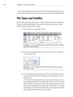
Autodesk Revit Architecture 2011 No Experience Required - part 18 ppsx
Bạn đang xem bản rút gọn của tài liệu. Xem và tải ngay bản đầy đủ của tài liệu tại đây (516.08 KB, 10 trang )
Chapter 3 • Creating Views
144
Creating an Elevation
I saved the best view for last… or at least the most popular. Elevations are essen-
tial for any project—so essential, in fact, that Revit provides four of them before
you place a single wall into the model. The four shapes that represent houses that
were in the model at the beginning of the book are elevation markers, as shown
in Figure 3.72. These markers are typically handy but are most certainly in the
way now. The first thing we need to do is to move one of them out of the way. The
second thing we need to do is to create a few new ones!
To start manipulating elevations, follow along:
1. Go to the Level 1 floor plan. In the eastern part of the corridor, there
is an elevation. Yours may be in a slightly different location than the
book’s example, but it needs to be moved nonetheless (see Figure 3.72).
FIGURE 3.72 The elevation marker is right in the way!
The action we are about to perform is moving the elevation marker.
To move an elevation marker, however, we need to break down what
an elevation marker is composed of. It is actually two separate items.
The square box is the elevation. The triangle is the part of the marker
that activates the view, as shown in Figure 3.73. To move this eleva-
tion marker, you must pick a window around both items and move
Creating an Elevation
145
them together. If you do not, the actual view will stay in its original
location, leaving you wondering what is wrong with your elevation.
FIGURE 3.73 The elevation marker is broken down into two pieces. Both
need to be moved together by picking a window around the entire symbol.
2. Pick a window around the elevation marker. Make sure you are not
picking any other items along with it.
3. Move your mouse over the selection. Your cursor will turn into a move
icon with four move arrows, as shown in Figure 3.74.
4. Drag the elevation marker to the west side of the building, as shown in
Figure 3.74.
FIGURE 3.74 You can drag the elevation marker after the entire item is
selected.
Chapter 3 • Creating Views
146
Now that the elevation marker is out of the corridor, it is time to make a new
one. To do so, make sure you are in the Level 1 floor plan and follow along:
1. On the View tab, click the Elevation button, as shown in Figure 3.75.
2. After you click the Elevation button, move your cursor around the
perimeter of the building. Notice that the elevation marker will follow
the profile of the exterior walls. This is a great thing!
WARNING
When you are choosing to create an elevation of a
radial wall, or nonlinear item, be sure you know exactly at which angle you
are placing the elevation marker. When you are in the elevation view, you may
get a false sense of the true dimensions based on the view’s perspective. Draw
a reference plane if you need to, and then place the elevation on that plane.
FIGURE 3.75 The Elevation button on the View tab
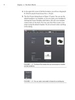
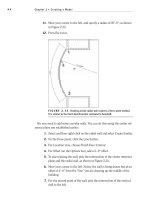
3. Pick a place for the elevation, as shown in Figure 3.76, and press Esc
to terminate the command.
4. When the elevation is placed, select the triangle. You will see the same
extents window as you saw in the previous section (see Figure 3.76).
This controls how deep into the model you are viewing, and it also
shows you the length of the section. Because you placed this elevation
up against a wall, Revit will stop the elevation at that wall.
5. Pick the top grip and stretch the elevation past the wall, as shown in
Figure 3.76.
Creating an Elevation
147
FIGURE 3.76 The elevation is placed. You can select the view arrow and
move the extents of the elevation into the building.
6. In the Project Browser under Elevations (Building Elevation), you
will see a new elevation. Right-click on it and rename it to West Wing
Southeast Elevation.
7. Open the elevation.
8. On the View Control bar, change the scale to 1/4” = 1’–0”.
9. On the View Control bar, set the detail level to Fine.
10. Save the model.
You have added a new exterior elevation. You can add an interior elevation as
well. It is just as easy and much more fun!
Interior Elevations
The difference between an exterior elevation and an interior elevation is the
same as the difference between a building section and a wall section. Both inte-
rior and exterior elevations are executed the same way: by selecting the View tab
on the Design bar. The only difference is that you can make a choice between
the two in the Type Selector in the Options bar. To add an interior elevation,
perform these steps:
1. Go to the Level 1 floor plan.
Chapter 3 • Creating Views
148
2. On the View tab, select the Elevation button.
3. In the Properties dialog box, choose Elevation : Interior Elevation, as
shown at the top of Figure 3.77.
4. Hover your cursor in the corridor near a point shown in the middle
of Figure 3.77. Notice that when you move your cursor up, the arrow
flips up. When you move your pointer down, the arrow flips down.
5. Make sure the arrow in the elevation target is pointing up and
pick a point along the horizontal corridor, as shown at the right of
Figure 3.77, to place the elevation. Once it’s placed, press Esc to ter-
minate the command.
6. After you place the elevation, you will notice that the extents will be
outside the building (in most cases this occurs; if it does not, you are
good to go). Select the elevation again, and on the right side, pick the
blue grip and drag the right extent to the point shown at the right in
Figure 3.77.
7. In the Project Browser, you will see that you have a new elevation
under the Elevations (Interior Elevation) category. Right-click the
new elevation (Revit will call it Elevation 1 - a, or something similar)
and call it East Wing Corridor Elevation.
FIGURE 3.77 Adding an interior elevation and making the adjustments
Creating an Elevation
149
8. Open the new view called East Wing Corridor Elevation.
9. Notice the crop region extends all the way up to the parapet. Select the
crop region and drag the top down to Level 2, as shown in Figure 3.78.
FIGURE 3.78 Stretching the grip down to crop the view
NOTE
If you had floors already placed in the model, Revit would cre-
ate the interior elevation to only extend to this geometry. Since we do not have
floors, Revit does not know where to stop. If you happen to place an elevation
without floors, and then you put them in later, Revit will not make the adjust-
ment. You still have to create the interior elevation manually for the new floors.
Let’s create some more elevations, shall we?
1. Go to Floor Level 1. Zoom into the east wing entry area, as shown in
Figure 3.79.
2. On the View tab, select the Elevation button.
3. Place an elevation marker in an area similar to the one shown in
Figure 3.79, and then move it to the center of the lobby.
TIP
Notice that when you are trying to place the elevation in the entry
area, it seems to be wandering all over the place. This is because the eleva-
tion is trying to locate the radial geometry. The safest bet in this situation is
to find a straight wall and “aim” the elevation at that wall. In this case, you
should aim the elevation at the bottom of the elevator shaft. When the eleva-
tion marker is in place, you can then move it to where you need it to be.
O
In the elevation’s
view, you can drag
the crop region
down to show only
that floor. If you
would rather see all
of the floors, per-
haps you should use
a section rather than
an elevation.
Chapter 3 • Creating Views
150
FIGURE 3.79 Add the elevation marker as shown here, and then move it to
a new location.
4. With the elevation marker centered in the lobby, select the round
bubble. Notice that four blue boxes appear, as shown in Figure 3.80.
These boxes let you turn on multiple views. Turn on all four views, as
shown in Figure 3.80.
FIGURE 3.80 Turn on all four views in the lobby.
With the four elevations turned on, you have some naming to do! Up to this
point, you have been going to the Project Browser to rename the elevations. Let’s
explore another way to rename an elevation and to view its properties as well.
Creating an Elevation
151
Elevation Properties
With each view comes a new set of properties. For example, when you made the
perspective view of the corridor you set Visual Style to Shaded With Edges, and
you turned the shadows on. Normally, in an interior elevation you do not want to
do this. Revit allows you to have separate view properties on a view-by-view basis.
To access the View Properties dialog, follow these steps:
1. On the interior elevation with the four arrows, select only the arrow
facing up (north).
2. In the Properties dialog, notice you have a wealth of information about
that view. You also have a multitude of options as well. The option we
are going to change is View Name, as shown in Figure 3.81. Find View
Name under the Identity Data heading, and change it to East Wing
Entry North Elevation, as shown in Figure 3.81.
FIGURE 3.81: Changing the View Name setting to East Wing Entry North
Elevation
3. Select the East Wing Entry North Elevation again. Notice the view’s
extents are stretching past the entry atrium. Pick the blue grips
By changing
the value in the
Properties dialog,
you are, in effect,
changing the name in
the Project Browser.
Again, change some-
thing in one place,
and it will change in
another.
O
Chapter 3 • Creating Views
152
at the end of the elevations and bring them into the atrium area, as
shown in Figure 3.82. Also, drag the view limit up to show the radial
exterior wall (see Figure 3.82).
FIGURE 3.82 Making the adjustments to bring the view back into a
reasonable range
4. Right-click on the elevation arrow facing left (west).
5. Change View Name to East Wing Entry West Elevation.
6. Right-click on the arrow facing down (south).
7. Change View Name to East Wing Entry South Elevation.
8. Right-click on the arrow facing right (east).
9. Change View Name to East Wing Entry East Elevation.
10. Select each elevation, and adjust the view’s extents as you did for the
north elevation.
11. Save the model.
Notice that the actual view names are showing up in the plan. This is nice, but
unfortunately it leaves no room for anything else other than the actual view. Plus,
no construction documents have these names right in the plan (at least none that
I have ever seen). We can turn this feature off.
Now that we can place and modify annotations, let’s delve into the physical
properties of these annotations.
Creating an Elevation
153
Annotation Properties
Annotations all have properties we can modify. To change the elevation symbol
properties, follow along:
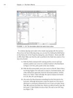
1. On the Manage tab, click Settings
➢ Additional Settings ➢ Elevation
Tags.
2. At the top of the Type Properties dialog, you will see Family: System
Family : Elevation Tag. Below that you will see Type. Change Type from
1/2” square to 1/2” circle (see Figure 3.83).
3. In the Type Parameters, under Graphics, change the Elevation Mark
to Elevation Mark Circle - Upgrade : 1/2”.
FIGURE 3.83 Modifying the properties for the elevation markers
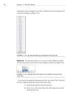
4. Click OK.
5. Zoom back in on the elevation markers. They should look like Figure 3.84.
FIGURE 3.84 The revised, less obtrusive elevation markers