Autodesk Revit Architecture 2011 No Experience Required - part 23 pot
Bạn đang xem bản rút gọn của tài liệu. Xem và tải ngay bản đầy đủ của tài liệu tại đây (569.6 KB, 10 trang )
Chapter 4 • Working with the Revit Tools
194
The last section in this chapter will focus on actual practice. We now have five
floors in the east wing alone, and we must add a layout to them. We also need to
add a layout to the west wing.
yo u Mu st hee d th e Wa r n i n g !
If you see a warning dialog while pasting elements that says you have just
created a duplicate and double counting will occur, stop and undo the paste.
Determine why Revit issued that warning. Did you already paste these
elements to this level? Sometimes the top of the walls are above the level
above. You can check this as well.
Creating the Plans
Now that you have added walls, doors, and windows, you can start to combine
this experience with your knowledge of the basic Revit editing commands. In
the previous section, you started to lay out the programs for your floor plans.
You can follow along with the book’s examples up to floor 3. You can create
your own plans for floors 4 and 5.
To get started, open the model you have been working on. If you have not com-
pleted the previous tasks, open the file called
NER-14.rvt at the book’s website,
www.sybex.com/go/revit2011ner. Go to Chapter 4 to find the file.
To start building a floor plan to be copied to other levels, follow these steps:
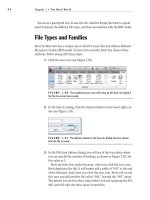
1. In the Project Browser, go to Level 1 under Floor Plans.
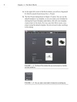
2. Start adding walls, doors, openings, and windows to resemble Figure 4.52.
These doors and windows can be any type you like. If your model varies
slightly from the example in the book, don’t be concerned.
3. In the Project Browser, go to Level 2.
4. Press Esc to clear any selection.
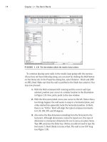
5. In the Properties dialog, set Underlay to None, as shown in Figure 4.53.
Creating the Plans
195
FIGURE 4.52 The first floor layout for the east wing
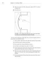
6. Create a floor plan layout similar to Figure 4.54. Make all of the dimen-
sions as even and as round as possible. Use all the commands and func-
tions you have learned up to this point.
7. For the windows, go to a 3D view, and using Copy/Paste, align them up
all the way to Level 5. This way, you know your windows are aligned,
and you can follow this procedure in your room layout for each floor
(see Figure 4.55).
WARNING
When you use Copy/Paste, you may get the same
Duplicate Value warning mentioned earlier. If you do, stop and undo. Make
sure you are not pasting windows over the top of windows.
8. Go to Level 3, and create a floor plan similar to Figure 4.56. We did
this by using Copy And Paste
➢ Aligned To Selected Levels from
Level 1. We added one wall to the northeast suite.
9. Go to Level 4 and create your own floor plan. The book will give no
example. You are on your own!
Chapter 4 • Working with the Revit Tools
196
10. Create one more floor plan for Level 5. Again, design your own lay-
out. Be as creative as you wish.
11. Save the model.
FIGURE 4.53 Switch Underlay from Level 1 to None.
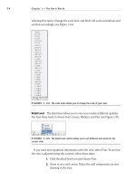
FIGURE 4.54 The layout for Level 2. Try to make the dimensions as even as possible,
consistent with what is shown here.
Creating the Plans
197
FIGURE 4.55 Using Copy/Paste, align the windows to the higher floors.
This will influence your floor layout for each level.
FIGURE 4.56 Level 3: This was mostly copied from Level 1 with the
exception of the 18
′–0″ room that was added.
If you got through that last procedure, and you are happy with the results,
you are on your way to being efficient in Revit. This is because you just created a
floor plan on your own. These last few steps were created to prove that Revit can
be quite intuitive when approached with just a little experience.
Chapter 4 • Working with the Revit Tools
198
If you are not comfortable with your results in this section, that’s OK. I had
an uncomfortable feeling the first time through, too. Take a deep breath, and go
back through where you think you got lost. Feel free to send me an e-mail mes-
sage if you have questions or concerns.
Are You Experienced?
Now you can…
use common editing commands to alter the appearance of your model
use reference planes to establish good, accurate methods of layout
array items, and change the count, length, and radius if needed
align items and keep them constrained
use locks to constrain the alignment of one element to another
split items to remove a segment or to turn one item into two
use the Copy And Paste
➢ Aligned To Selected Levels commands to
create multiple floors that are similar in layout
CHAPTER 5
Dimensioning
and Annotating
The focus of this chapter is to give you the ability to dimension and anno-
tate a model. After the novelty of having a really cool model in 3D wears off,
you need to buckle down and produce some bid documents. This is where
Revit must prove its functionality. You should ask yourself, “Can Revit pro-
duce drawings consistent with what is acceptable to national standards, and
more importantly, my company’s standards? And if so, how do I get to this
point?” These are the questions the owners and managers will ask you. (If
you are, in fact, an owner or a manager, I suppose you can still just ask your-
self these questions.)
Dimensioning
Using dimensions as a layout tool
Placing text and annotations
Chapter 5 • Dimensioning and Annotating
200
Dimensioning
The answers to these questions begin right here with dimensioning and annota-
tions. This is where you can start to make Revit your own. Also, when it comes to
dimensioning, you will find in this chapter that dimensions take on an entirely
new role in the design process as well.
I think you will like dimensioning in Revit. It is almost fun. Almost. Before we
get started, we should get one thing out of the way: you cannot alter a dimension
to display an increment that is not true. Hooray! As you go through this chapter,
you will quickly learn that when you place a dimension, it becomes not only an
annotation but a layout tool as well.
The dimension command has five separate types: Aligned, Linear, Angular, Radial,
and Arc Length. Each has its importance in adding dimensions to a model, and each
will be covered separately.
Let’s get started. To begin, open the file you have been following along with. If
you did not complete the previous chapter, go to the book’s website at www.sybex
.com/go/revit2011ner. From there you can browse to Chapter 5 and find the file
called
NER-16.rvt.
Aligned Dimensions
The most popular of all the Revit Architecture dimensions is the Aligned dimen-
sion. This type of dimension will be used 75 percent of the time.
An aligned dimension in Revit allows you to place a dimension along an object
at any angle. The resulting dimension will align with the object being dimen-
sioned. A Linear dimension, however, will add a dimension only at 0, 90, 180, or
270 degrees regardless of the item’s angle.
To add an aligned dimension, perform these steps:
1. Go to the Level 1 floor plan.
2. Zoom in on the east wing of the building.
3. On the Annotate tab, click the Aligned button, as shown in Figure 5.1.
4. On the Options bar, you will see a drop-down menu with some choices,
as shown in Figure 5.2. Make sure that you have Wall Faces selected.
5. The next menu lets you pick individual references or entire walls.
Select Entire Walls from the menu, as shown in Figure 5.2.
Dimensioning
201
FIGURE 5.1 Starting the Dimension command from the Annotate tab
FIGURE 5.2 The Options bar for the Dimension command. Notice the Options button at
the far right.
6. On the far right of the Options bar is an Options button, which leads
you to options you can choose from when selecting the entire wall.
Click the Options button.
7. In the Auto Dimensions Options dialog, select Intersecting Walls. Do
not select any other item (see Figure 5.3), and then click OK.
8. Zoom in on the north wall, as shown in Figure 5.4.
9. Pick (left-click) the north exterior wall. Notice that the dimensions
are completely filled out.
10. Pick a point (to place the dimension) approximately 8
′ above the
north wall (see Figure 5.4).
Chapter 5 • Dimensioning and Annotating
202
FIGURE 5.3 The Auto Dimension Options dialog
FIGURE 5.4 By choosing the Pick Entire Walls option, you can add an entire string of
dimensions in one click.
11. In true Revit form, you are still in the command unless you tell Revit
you do not want to be. In this case, click the Options button on the
Options bar (the same one you clicked before).
12. Uncheck Intersecting Walls in the Auto Dimension Options dialog
and click OK.
13. Pick (left-click) the same wall. You now have a dimension traveling
the entire length of the building.
14. Move your cursor above the first dimension string you added. Notice
the dimension will “click” once it gets directly above the first string.
15. When you see the dimension snap, pick that point (see Figure 5.5).
In many cases, you will need the ability to pick two points to create the dimen-
sion. What a world it would be if everything was as easy as the dimension string
we just added. Unfortunately, it is not.
Dimensioning
203
FIGURE 5.5 Adding a major dimension by turning off the Intersecting Walls choice in
the Auto Dimension Options dialog
Aligned Dimensions by Picking Points
Nine times out of ten, you will be picking two points to create the dimension.
Usually in Revit this is quite simple—until you get into a situation where the
walls are at an angle that is not 90°. In a moment we will explore that issue, but
for now, let’s add some straight dimensions:
WARNING
Before you get started, note that this procedure is
not easy. If it does come easily to you, great! If not, don’t get discouraged.
Keep trying.
1. Zoom in on the northeast portion of the east wing, as shown in
Figure 5.6.
2. On the Annotate tab, click the Aligned button.
3. On the Options bar, choose Individual References from the Pick
menu, as shown in Figure 5.6, and do the following:
a. Pick the north wall.
b. Pick the horizontal wall that ties into the radial wall, illustrated
as “2” in Figure 5.6.
c. Place the dimension about 8
′ to the right of the vertical wall, as
shown in Figure 5.6.