Autodesk Revit Architecture 2011 No Experience Required - part 24 pptx
Bạn đang xem bản rút gọn của tài liệu. Xem và tải ngay bản đầy đủ của tài liệu tại đây (529.72 KB, 10 trang )
Chapter 5 • Dimensioning and Annotating
204
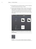
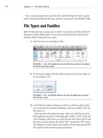
FIGURE 5.6 Placing the dimension by picking two objects
4. With the Aligned dimension command still running, pick the north
wall again and do the following:
a. Pick the outside face of the northern wall.
b. Pick the centerline of the door, as shown in Figure 5.7, but do
not press Esc, or terminate the command.
c. Pick the horizontal wall that ties into the radial wall, illustrated
as “3” in Figure 5.7.
d. Pick a point inside (to the left of) the first dimension, as shown
in Figure 5.7. This will place the dimension string and finalize
the session.
WARNING
When you add a string of dimensions, you must not
stop and then resume the dimension string in the middle of the command.
As you will see in a moment, when you add dimensions in a continuous line,
there is a lot you can do in terms of making adjustments to the objects you
are dimensioning.
You will now see that the actual dimension values are blue. Also,
you will see a blue EQ icon with a dash through it. (Refer back to
Figure 5.7.)
Dimensioning
205
5. Click the blue EQ button, as shown in Figure 5.8. If the door was not
exactly centered, this will force the door to move to an equal distance
between the two walls.
6. Press Esc.
FIGURE 5.7 Adding a dimension string manually
FIGURE 5.8 You can use the dimension string to move the door by clicking
the EQ button.
Sometimes you may want to display the dimensions rather than the EQ that
Revit shows as a default. To do so, follow along:
1. Select the dimension.
2. Right-click.
3. Choose EQ Display, as shown in Figure 5.9.
Chapter 5 • Dimensioning and Annotating
206
The dimensions will now show an increment.
FIGURE 5.9 Toggle off the EQ Display.
Pretty cool. There is one last item involving aligned dimensions that we
should address: How you dimension along an angle?
Dimensioning an Angle
No, not an “angel,” an angle. Adding this type of aligned dimension is not the
easiest thing to do in Revit. This is why we need to address the process as a sepa-
rate item in this book.
1. Zoom in on the corridor area (the link area between the east and
west wings).
2. On the Annotate tab, click the Aligned button on the Dimension panel.
3. On the Options bar, be sure Pick is set to Individual References.
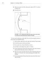
4. Zoom in close to the intersection of the two walls, shown in Figure 5.10.
5. Hover your pointer over the core intersection, as shown in Figure 5.10.
6. Tap the Tab key until you see the square grip appear.
NOTE
By tapping the Tab key, you tell Revit to filter through different
points. When you arrive at the square grip, Revit can dimension the angled wall.
7. When the square grip appears, pick it (left-click), as shown in Figure 5.10.
8. Move to the other intersection of the angled wall.
9. Hover your cursor over this core intersection, as shown in Figure 5.11.
10. Tap the Tab key until you see the same square grip.
11. Pick the square grip.
Another way to tell
Revit how to display
the dimensions is to
select the dimension,
and then look at the
properties. Here, you
will be given addi-
tional choices.
Dimensioning
207
12. Now the dimension is following your pointer. Pick a third point about
8
′ away from the angled wall, as shown in Figure 5.11.
13. On the left end of the Ribbon, select the Modify button. This will end
the command.
FIGURE 5.10 Press the Tab key to select the point shown.
FIGURE 5.11 Picking the second point along the wall and placing the
dimension
Chapter 5 • Dimensioning and Annotating
208
Unfortunately, we had to dimension to the core of the wall. This is the last place
we would ever need to take a dimension from. At this point, the dimension needs
to be “stretched” to the outside finished face of the brick, as you’ll see next.
Editing the Witness Line
Every dimension in Revit Architecture has its own grip points when selected. This
is similar to most CAD applications. Two of these grips control the witness line.
The witness line is the line “attached” to the item being dimensioned. Because we
had to take this dimension from the core of the wall, the witness lines need to be
dragged to the outside face of the brick.
1. Select the angled dimension. Notice the blue grips appear.
2. On the left side of the dimension, pick and hold the grip in the middle
of the dimension line, as shown in Figure 5.12.
3. Drag the blue grip to the outside face of the brick. You will know you
are in the right spot because you will see a small dot appear, as shown
in the magnified segment of Figure 5.12.
FIGURE 5.12 Dragging the witness lines grip
4. Repeat the procedure for the other side.
Trust me—this is worth practicing now, before you get into a live situation. If
you have already run into this situation, you know exactly what I mean.
We need to look at one more procedure for tweaking an aligned dimension:
overriding a dimension’s precision.
Dimensioning
209
Overriding the Precision
When you dimension a wall at an angle such as this, the dimension usually
comes out at an uneven increment. In most cases, you do not want to override
every dimension’s precision just for this one, lone dimension to read properly.
In this situation, you want to turn to the dimension’s Type Properties:
1. Select the angled dimension.
2. In the Propertied dialog, click the Edit Type button as shown in
Figure 5.13.
FIGURE 5.13: Clicking the Edit Type button to begin creating a new
dimension style
3. Click the Duplicate button, as shown in Figure 5.14.
4. In the Name dialog box that opens, name the new dimension style
Linear - 3/32
″ Arial - 1/4″ precision. Click OK.
5. Scroll down to the Text category. There, near the bottom, you will see
a row for Units Format. Next to the Units Format row is a button that
displays a sample increment. Click it (see Figure 5.14).
6. Uncheck Use Project Settings.
7. Choose To the Nearest 1/4
″ from the Rounding drop-down menu (see
Figure 5.15).
Chapter 5 • Dimensioning and Annotating
210
8. Click OK twice.
9. Notice the dimension is now rounded to the nearest 1/4
″. In this case,
it is rounded to a whole number.
FIGURE 5.14 Select the button in the Text category to access the
dimension’s precision.
Although aligned dimensions will bear the brunt of your dimensioning, there
are still plenty of other dimension types waiting for you to use.
FIGURE 5.15 Changing the dimension’s precision. Notice some of the other available
choices.
Dimensioning
211
Linear Dimensions
Linear dimensions are used less frequently than most of the other dimensions.
Unlike in AutoCAD, where linear dimensions are the go-to dimension, they are
put on the bench for most of the game in Revit. The best use for a linear dimen-
sion is when you want to put a straight dimension across nonlinear (angled)
geometry, as follows:
1. Zoom back in on the corridor area.
2. On the Annotate tab, select the Linear Dimension button. Notice that
you cannot select the entire wall. That option has been taken away.
Instead, Revit requires you to pick a point.
3. Move your cursor over the inside corner at the bottom intersection of
the corridor, as shown in Figure 5.16. Make sure you are exactly over
the exterior intersection of the brick. You will know you are there by
the white dot that shows up, as shown in Figure 5.16.
4. Once you see the dot, pick the corner.
5. Pick the same spot on the other side end of the wall, as shown in
Figure 5.17. When you pick the second corner, the dimension will fol-
low your cursor in a straight direction.
6. Move your cursor to the left approximately 8
′ past the first point
that you picked, and pick the third point to place the dimension (see
Figure 5.17).
7. Press Esc.
8. Select the new dimension.
9. In the Modify dimensions Properties dialog, select the Linear - 3/32
″
Arial - 1/4
″ style, as shown in Figure 5.18.
10. The dimension is now rounded to the nearest 1/4
″.
Aligned and linear dimensions are the two dimension styles that pertain to
straight dimensioning. The next three dimension procedures add dimensions to
angled and radial geometry.
Chapter 5 • Dimensioning and Annotating
212
FIGURE 5.16 Selecting the finished exterior corner of the brick. You will
see a small white dot appear, indicating you can pick the start of the dimension.
FIGURE 5.17 When you add a linear dimension to an angled wall, you will
get a straight dimension.
Dimensioning
213
FIGURE 5.18 Changing the dimension to reflect the new rounded dimension
Angular Dimensions
Angular dimensioning comes close to needing no introduction at all. But I will
introduce it anyway.
Angular dimensions are used to calculate and record the angle between two
items. These two items are usually walls. Of course, we will add an angular
dimension to our lovely corridor walls:
1. Zoom back in on the corridor if you are not there already.
2. On the Annotate tab, select the Angular Dimension button, as shown
in Figure 5.19.
3. For the first wall, pick the finished inside face of the upper-left corridor
wall, as marked by “1” in Figure 5.19.
4. Pick the finished inside face of the angled corridor wall, as marked by
“2” in Figure 5.19.
5. Move your cursor to the left about 8′, and place the dimension as marked
by “3” in Figure 5.19.
6. Press Esc.