Autodesk Revit Architecture 2011 No Experience Required - part 34 ppsx
Bạn đang xem bản rút gọn của tài liệu. Xem và tải ngay bản đầy đủ của tài liệu tại đây (683.89 KB, 10 trang )
Chapter 7 • Roofs
304
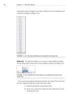
NOTE
Although you have pretty good experience with walls up to
this point, Chapter 16, “Advanced Wall Topics,” is dedicated to the advanced
concepts and creation of wall systems.
It’s now time to add the roof to the corridor. Because the walls our roof will
bear on are now correct, the rest will be a snap!
1. Go to the Level 3 floor plan. (This is the roof level for our corridor.)
2. On the Home tab, select Roof ➢ Roof By Footprint.
3. On the Draw panel, make sure the Pick Walls button is selected.
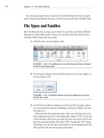
4. On the Options bar, make sure the Defines Slope button is checked,
as shown in Figure 7.23.
5. Type 1
′–0″ in the Overhang field.
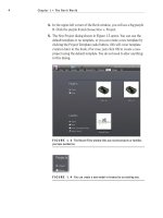
6. Pick the six walls that comprise the corridor, as shown in Figure 7.23.
FIGURE 7.23 Pick these walls for the roof’s footprint.
Remember, your
preview will need
to be in Section :
Modify Type for all
of the buttons to be
active.
Placing Roofs by Footprint
305
With the easy walls out of the way, it is now time to create the gable ends. You
should still be in the Pick Walls mode. This is OK, but there are a few things you
need to change on the Options bar:
1. Click the Boundary Line button on the Draw panel, as shown in
Figure 7.24.
2. On the Draw panel again, click the Pick Lines icon.
3. On the Options bar, uncheck Defines Slope.
4. For the offset, enter 0 (see Figure 7.24).
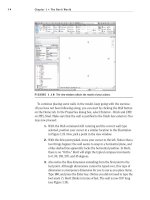
5. Pick the east wall on the west wing, and the west wall of the east
wing, as shown in Figure 7.24.
FIGURE 7.24 You must pick lines to trace the terminating walls of the roof.
It’s cleanup time! Of course the magenta lines are overlapping at the long
walls. This is OK—you are an expert at the Trim command by now, especially in
Sketch Mode:
1. On the Modify | Create Roof Footprint tab, select the Trim/Extend
Single Element command, as shown in Figure 7.25.
O
As you pick the
walls, notice that
you now have an
overhang. This
overhang obviously
needs to extend to
the outside of the
walls. Just be con-
scious of this as you
pick the walls and
watch your align-
ment lines as you
proceed.
Chapter 7 • Roofs
306
2. Trim the intersections that overlap. There will be four of them (see
Figure 7.25).
3. On the Mode panel, click Finish Edit Mode.
FIGURE 7.25 Using the Trim command in conjunction with the roof sketch.
One ugly roof, huh? Welcome to the world of pitched roofs in Revit. We will
get the roof we want—we just need to add two roofs here. You will understand
this process, but it is going to involve patience and trial and error!
To fix this roof, you simply have to make two separate roofs and join them
together. This will be a common procedure for the more complicated roof sys-
tems in Revit.
1. Select the roof.
2. On the Modify | Roofs tab, click the Edit Footprint button, as shown
in Figure 7.26.
3. Delete every line, other than the three shown in Figure 7.27.
4. On the Draw panel, click the Line button.
Placing Roofs by Footprint
307
5. Draw a diagonal line from the endpoints of the two lines, as shown in
Figure 7.28.
FIGURE 7.26 Selecting the roof and clicking the Edit Footprint button
FIGURE 7.27 Keep these three lines.
FIGURE 7.28 Draw a diagonal line as shown.
Chapter 7 • Roofs
308
6. On the Modify | Roofs ➢ Edit Footprint tab, click Finish Edit Mode.
7. The roof will display. It still looks funny, but we will take care of that
by altering the view range.
8. Start the Roof ➢ Roof By Footprint command again on the Home tab.
9. On your own, sketch the roof shown in Figure 7.29. Make sure the
lines along the walls are defining a slope. The lines that represent the
ends of the roof do not slope.
10. To add the line that matches the roof to the right, make sure you
have the Boundary Line button selected on the Draw panel and that
you have Pick Lines selected as well. Now, simply pick the roof to the
right, and the line will appear.
11. Review Figure 7.29 to see if your sketch matches. You should have six
lines total, and the right and the left ends should not have a slope.
FIGURE 7.29 The new outline of the second roof
12. On the Modify | Create Roof Footprint tab, click Finish Edit Mode.
13. Go to a 3D view. Does your roof look like Figure 7.30?
If you accidentally
added a line with
(or without) a slope,
that’s fine. You can
change it. First,
press Esc (to clear
the command), and
then select the line
that needs to be
changed. On the
Options bar, you can
check (or uncheck)
Defines Slope.
Placing Roofs by Footprint
309
FIGURE 7.30 The corridor roof in 3D
The walls need some help! They are indiscriminately poking up through the
roof. You need to do some wall cleanup. First you need to force the walls to use a
mitered join at the 45° intersections. The following procedure will show you how:
1. Go to the Level 1 floor plan.
2. Zoom into the wall intersection, as shown in Figure 7.31.
3. On the Modify tab, click the Wall Joins button, as shown in Figure 7.31.
4. Move your cursor over the intersection. You will see a box form around
the corner. When you see this box, pick the wall.
5. On the Options bar, click the Miter radio button, as shown near the
top left in Figure 7.31. Notice the walls are now joined at a miter.
6. Perform this procedure at all four corners.
Chapter 7 • Roofs
310
FIGURE 7.31 Modifying the wall’s corners
You can now attach the tops of the walls to the bottom of the roof:
1. Go back to a 3D view and select one of the corridor walls.
2. On the Modify | Walls tab, notice there is an option to attach the top or
base of the wall, as shown in Figure 7.32. Click the Attach Top/Base
button.
3. Pick the roof that the wall is under. You will see that the wall no lon-
ger sticks up past the roof.
4. Perform steps 1 through 3 for each corridor wall. When you are fin-
ished, your corridor should be spanking nice, like Figure 7.33.
FIGURE 7.32 Attaching the top or the base
When you have suc-
cessfully mitered a
corner and are ready
to move to the next,
there is nothing indi-
cating that you can
safely pick another
corner. You do not
need it. When you
see that the walls
are at a miter, you
can pick the next
intersection. When
you have finished all
four, just press Esc.
You don’t always
have to modify the
wall’s mitering. This
is a special situation
where the corners
will not attach to the
roofs properly unless
you do so. There’s
really no explanation
for why and when
this will occur. Just
know you have some
tools under your belt
to get out of these
“real life” situations.
Placing Roofs by Footprint
311
FIGURE 7.33 The completed corridor roof
bu t i go t th i s Wa r n i n g !
Sometimes Revit does not like you hacking up its perfectly fine walls. The
warning shown in the following image is common and has no effect on the
model. You can just ignore it.
Viewing a Sloped Roof in Plan
Back in Level 3 (the level in which the corridor roof resides), we are having a
view problem: the roof is only showing up to the cut plane for that level. This
just cannot be. There is a procedure to correct this called a plan region:
1. Press Esc if the last command is still running and go to the Level 3
floor plan.
2. On the View tab, click the Plan Region button, as shown in Figure 7.34.
3. On the Draw panel, select the Rectangle button, as shown in Figure 7.35.
Chapter 7 • Roofs
312
4. Draw a rectangle around the corridor, as shown in Figure 7.35. Be sure
to snap to the exact points where the corridor walls meet the taller walls
on the east and west wings.
5. In the Properties dialog, click the Edit button in the View Range row,
as shown in Figure 7.36.
FIGURE 7.34 Using a plan region allows you to alter the view range in a
specified area of a plan.
FIGURE 7.35 Creating the rectangle that forms the perimeter of the
plan region
Placing Roofs by Footprint
313
FIGURE 7.36 Setting the view range for the plan region
6. In the View Range dialog, set Top to Unlimited and Level 3 Cut Plane
Offset to 35
′–0″, as shown in Figure 7.36.
7. Click OK.
8. On the Modify | Create Plan Region Boundary tab, click Finish Edit Mode.
You can now see the roof in its entirety, as shown in Figure 7.37.
FIGURE 7.37 The finished roof plan
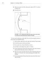
There is one more kind of roof to add. It will be a flat roof that has a slope in
one single direction. Although you can do this by simply creating a roof with one
edge specified as a pitch, there will be times where you will want a roof sloped at
an odd direction that can’t be handled by simply angling a roof edge.