Autodesk Revit Architecture 2011 No Experience Required - part 40 pot
Bạn đang xem bản rút gọn của tài liệu. Xem và tải ngay bản đầy đủ của tài liệu tại đây (836.72 KB, 10 trang )
Chapter 8 • Structural Items
364
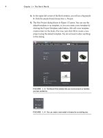
FIGURE 8.47 Adding the second rod to the canopy
15. Mirror the rods to the other canopy. You can stay in the East eleva-
tion to do so.
NOTE
If you receive a warning about a circular reference chain, sim-
ply click Unjoin Elements.
16. Save the model.
That pretty much covers it for framing. The next section will bring us under-
ground into the foundation. Although the structural engineer will usually specify
the foundation system, architects must have access to foundation tools to place
concrete foundation walls as well as strip and isolate footings and piers. The next
section will address these topics.
Foundation Systems
The first question that arises while addressing structural foundations is, “What if
the architect places a foundation in the model, and then the structural engineer
places one in their model?”
What will happen is the structural engineer will use a method called Copy/
Monitor whereas the engineer takes the architect’s foundation and makes it
their own. The engineer is then free to alter the foundation. This method will
be addressed fully in Chapter 20, “Importing and Coordinating Revit Models.”
The first topic in this section will focus on creating foundation walls. Although
adding this type of wall is similar to adding architectural walls, there are a few
things you want to look out for.
Foundation Systems
365
Foundation Walls
For now, let’s add a foundation and deal with coordination later. The task before
us here is to create a foundation wall constructed of 18
″ of solid concrete. To
proceed, follow these steps:
1. Go to the Level 1 floor plan.
2. Click the Wall ➢ Structural Wall button on the Structure tab, as
shown in Figure 8.48.
3. In the change Element Type menu at the top of the Properties panel,
select Generic 8
″ Masonry.
4. Click the Edit Type button.
5. Click the Duplicate button.
6. Name the new wall 18
″ Concrete.
7. Click OK.
8. In the Function row, select Foundation from the drop-down list, as
shown in Figure 8.48.
9. Just under the Function row is the Coarse Scale Fill Pattern row.
Change the hatch to Concrete by clicking the […] button and select-
ing Concrete from the menu. Click OK.
10. Click the Edit button in the Structure row.
11. In the second row in the Layers chart, click in the Material cell.
12. Click the […] button.
13. Find Concrete - Cast-in-Place Concrete.
14. Click OK.
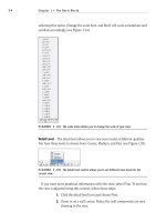
15. Change the Thickness to 1
′–6″ (see Figure 8.49).
16. Click OK twice.
17. Press Esc.
The reason we press Esc and basically bailed out at the last second is that we
are about to place a wall underneath this level. This view is currently set to not
show anything below this level, forcing us to alter the view range.
Chapter 8 • Structural Items
366
FIGURE 8.48 Changing Function to Foundation
FIGURE 8.49 Changing the Material and Thickness settings
Foundation Systems
367
To modify the view range, follow these steps:
1. In the Properties dialog, scroll down to View Range and click the Edit
button.
2. For Primary Range, set Bottom Offset to –1′–0″.
3. For View Depth, set Level Offset to –1
′–0″.
4. Click OK.
5. Click the Wall
➢ Structural Wall button from the Home tab.
6. On the Draw panel, click the Pick Lines icon.
7. Make sure that Depth is set to T.O. Footing on the Options bar.
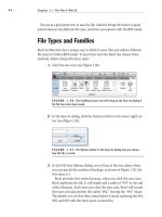
8. Pick the core centerline of the exterior wall, as shown in Figure 8.50.
9. Keep repeating picking the exterior walls in all three sections of the
model.
FIGURE 8.50 Picking the core centerline of every exterior wall in the
entire model. This includes the corridor and both wings.
Your 3D model should look like Figure 8.51. Get into the habit of viewing the
model in 3D—especially when you can’t see exactly where the walls are being
placed in the plan.
Chapter 8 • Structural Items
368
FIGURE 8.51 The foundation walls
Now we can travel into the ground and check out how our walls are joining.
Some cleanup will be involved:
1. In the Project Browser, find the T.O. Footing floor plan and double-
click it.
2. Zoom into the east wing area where the south elevator meets the
foundation wall. There is an issue: the walls are funky, as shown in
Figure 8.52.
3. Select the masonry elevator shaft wall.
4. On the blue grip, right-click and select Disallow Join, as shown in
Figure 8.52.
5. Click the grip on the masonry wall (the same one you right-clicked
on to disallow the join), and drag it back to the outside face of the
corner, as shown in Figure 8.52.
6. The masonry wall to the right needs to be joined to the foundation
wall. To do this, click the Join Geometry button on the Modify tool-
bar, as shown in Figure 8.53.
7. Pick the foundation wall.
8. Pick the masonry wall. The masonry wall is now notched back for the
foundation.
9. Repeat the procedure for the north elevator. The condition may be
slightly different than the south elevator, but the process to fix it will
be the same.
Foundation Systems
369
FIGURE 8.52 The walls are not behaving as we would like them to.
FIGURE 8.53 Disallowing the wall’s join will enable the foundation walls to terminate
as expected.
Chapter 8 • Structural Items
370
Moving to the west wing, there is one wall we need to fix. The command we
will have to use is the Split command:
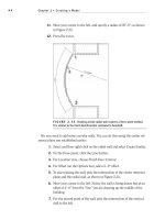
1. Zoom in on the area, as shown in Figure 8.54.
2. On the Modify tab, click the Split Element button, as shown in
Figure 8.54.
3. On the Options bar, click the Delete Inner Segment checkbox (see
Figure 8.54).
4. Pick the points labeled “1” and “2,” shown in Figure 8.54.
FIGURE 8.54 Splitting the foundation wall to follow the profile of the wall above
Now that the foundation walls are in place, it is time to think about what these
walls are bearing on. Revit Architecture has tools to add footings to the bottom of
these walls.
Adding Structural Footings
If you are going as far as placing structural foundation walls, you might as well
continue on and place footings underneath them, right? Luckily this is not a
difficult task.
Adding Structural Footings
371
Before we start adding the structural footings to the plan, we need to acknowl-
edge that, by default, this view is not set up to see any objects that are physically
below its level. To correct this, we must alter the view range of this specific plan.
1. Make sure you are still in the T.O. Footing plan, and click Esc twice to
end any active command.
2. In the Properties dialog, go to the View Range row and click Edit.
3. Set Primary Range Bottom to Unlimited.
4. Set View Depth Level to Unlimited, as shown in Figure 8.55.
5. Click OK.
FIGURE 8.55 Again with the View Range!
6. On the Foundation panel of the Structure tab, click the Wall
Foundation button, as shown in Figure 8.56.
FIGURE 8.56 Adding a Wall foundation
Chapter 8 • Structural Items
372
At the top of the Properties dialog box, notice it says Bearing Footing - 36″ × 12″.
This is a little big for our purposes, so let’s make a new one:
1. In the Properties dialog, click the Edit Type button.
2. Click Duplicate.
3. Call the new footing element Bearing Footing - 30
″ x 12″.
4. Click OK.
5. Change the Width setting to 2
′–6″, as shown in Figure 8.57.
FIGURE 8.57 Changing the width to 2′–6″
6. Click OK again to get back to the model.
7. Start picking walls. This footing will be centered underneath each
wall you pick.
8. When you are done picking the walls, go to a 3D view to make sure
you have all of the foundations covered, as shown in Figure 8.58.
When all the footings are in place, you can see that we need to focus on the
elevator shafts. Since we need an entire foundation mat underneath the eleva-
tors, we can use a structural slab.
Just because this
specific foundation
is labeled Wall does
not mean it is a wall.
It is labeled Wall
because it is a con-
tinuous (strip) foot-
ing that has a wall
bearing on it.
Structural Slabs
Structural slabs are basically really thick floors. The one we are about to use is
a 12
″-thick solid concrete floor. Of course, Revit does not have something this
thick already built in the library, so we will take this opportunity to make one:
1. Go to the T.O. Footing floor plan.
Adding Structural Footings
373
FIGURE 8.58 Doing a 3D investigation to see whether the footings are all in place
O
If you hover your
cursor over a wall
and press the Tab
key, Revit will select
all connecting walls,
allowing you to add
the bearing footing
in literally two clicks.
2. Zoom into the elevator area.
3. On the Foundation panel of the Structure tab, click Slab ➢ Foundation
Slab, as shown in Figure 8.59.
FIGURE 8.59 Clicking Slab ➢ Foundation Slab