Autodesk Revit Architecture 2011 No Experience Required - part 64 pot
Bạn đang xem bản rút gọn của tài liệu. Xem và tải ngay bản đầy đủ của tài liệu tại đây (550.34 KB, 10 trang )
Chapter 12 • Detailing
604
FiguRe 12.32 The new soldier brick in the model
Before we modify the bricks, let’s explore how a repeating detail is created.
The objective of the next procedure is to discover how a repeating detail works
and how we can create a new one.
1. Make sure you are in the detail called Roof Taper Section.
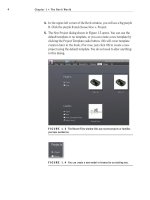
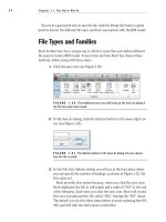
2. Select one of the repeating details, as shown in Figure 12.33.
3. In the Properties dialog, click the Edit Type button, as shown in
Figure 12.33.
4. Click into the Parameter list. Notice that every detail component
listed in your model is available. The detail component being used
here is Brick Standard : Running Section.
Notice also that you can change the spacing and the patterns of
how the repeating detail will perform.
5. Click Cancel.
The next objective is to modify the specific detail component that the repeat-
ing detail is using. To do so, we must add an instance of the detail component (in
this case it is Brick Standard : Running Section) and then edit the family. Once
we load it back into the model, the repeating detail will be up-to-date.
Drafting on Top of the Detail
605
FiguRe 12.33 Click the Edit Type button after selecting one of the brick
repeating details.
If you would like to give it a shot and do it on your own, go ahead. If you
would rather have some guidance, follow along:
1. On the Detail panel of the Annotate tab, click the Component ➢ Detail
Component button.
2. In the Type Selector on the Properties dialog, pick the Brick Standard :
Running Section detail component. (Remember, this was the compo-
nent that we discovered the repeating detail was using.)
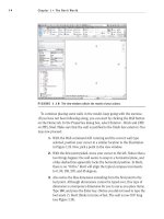
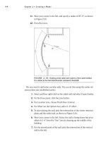
3. Place the detail component off to the side of the wall, as shown in
Figure 12.34.
4. Press Esc twice.
5. Select the Brick Standard : Running Section you just inserted.
6. On the Mode panel, click the Edit Family button.
7. Select the filled region.
8. On the Mode panel, click Edit Boundary.
9. Delete the right and left thick lines.
10. On the Draw panel, click the Line button.
Chapter 12 • Detailing
606
FiguRe 12.34
Place the Brick Standard : Running Section detail component
off to the side. You will later delete this occurrence of the component.
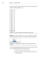
11. In the Type Selector menu in the Properties dialog, click Detail Items.
12. Draw the jagged lines in both sides, as shown in Figure 12.35.
13. Click Finish Edit Mode on the Mode panel.
14. On the Home tab, click the Line button.
15. On the Draw panel, click the arc passing through three points button.
16. In the Properties dialog, be sure Detail Items is chosen from the Type
Selector list.
17. Draw an arc on both sides of the brick, as shown in Figure 12.35.
FiguRe 12.35 Draw the textured face while you are in the Edit mode for
the filled region. Draw the arcs for the mortar joint using lines.
Drafting on Top of the Detail
607
18. When you are finished, save the new brick. You can also find
this brick at the book’s web page in Chapter 12; it’s called
Brick
Standard.rfa
.
19. On the Family Editor panel, click Load Into Project.
20. In the project, click to overwrite the family.
21. Delete the stray detail component you placed. We were only using it
for access to the family.
Compare your detail to the detail in Figure 12.36.
FiguRe 12.36 The brick actually looks like brick!
The next step is to anchor this façade back to the wall. Two things need to be
added. We will first add a structural relief angle above the soldier course, then a
brick tieback to a lower course.
1. On the Annotate tab, click the Component ➢ Detail Component button.
2. On the Mode panel, click the Load Family button.
3. Open the
Detail Components folder.
4. Go to
Div 05-Metals.
5. Go to
051200-Structural Steel Framing.
6. Double-click on the file
AISC Angle Shapes-Section.rfa.
Chapter 12 • Detailing
608
7. In the Type list, select L6X4X5/16.
8. Click OK. You will have to use the spacebar to flip the instance.
9. Place it into the model as shown in Figure 12.37.
10. Press Esc twice.
FiguRe 12.37 Placing the L6X4X5/16 angle
Of course the line weight is basically a blob, so we must modify the family in
order for it to look accurate. The next procedure is almost a review of what we
had to do to the bricks.
1. Select the angle.
2. On the Mode panel, click Edit Family.
3. In the Family Editor, select the filled region (it is the entire angle),
and click Edit Boundary on the Mode panel.
4. Select all the lines that comprise the perimeter of the angle.
5. In the Type Selector menu in the Properties dialog, select Detail
Items. (We are switching from heavy lines to Detail Items.)
Drafting on Top of the Detail
609
6. On the Mode panel, click Finish Edit Mode.
7. On the Family Editor panel, click Load Into Project.
8. Click Overwrite The Existing Version.
9. Adjust the angle so it looks like Figure 12.38.
FiguRe 12.38 The angle in place and looking like an angle
The next step is to find a fastener to anchor the angle back to the wall’s sub-
strate. There is a problem, however. The type of bolt we need is a lag bolt that is
power-driven from the exterior into the wall. Revit does not provide one out of
the box. Luckily the book you bought does! To find the lag bolt provided with
the book, go to the book’s web page, browse to Chapter 12, and find the file
called
A307 Lag_Bolt-Side.rfa.
1. To load the lag bolt into your model, go to the Insert tab and click the
Load Family button. Browse to the directory where you put the
A307
Lag_Bolt-Side.rfa
file.
2. With the lag bolt loaded, click the Component
➢ Detail Component
button on the Annotate tab.
3. Select A307 Lag_Bolt-Side : 3/4
″ from the Type Selector.
4. Insert the lag bolt into the angle as shown in Figure 12.39.
5. Press Esc twice.
Chapter 12 • Detailing
610
FiguRe 12.39 Inserting the lag bolt
The next step is to add a corrugated wall tie to the brick below the soldier course.
Since the brick is a pretty good distance away from the wall, we will also need to
add some wood blocking to the model.
1. On the Insert tab, click the Load Family button.
2. Go to the
Detail Components folder.
3. Go to
Div 06-Wood And Plastic.
4. Go to
061100-Wood Framing.
5. Click the file called
Nominal Cut Lumber-Section.rfa.
6. Select the 2
×6 type, and click OK.
7. Go to the Annotate tab, click the Component
➢ Detail Component
button, and place the 2
×6 into the wall, as shown in Figure 12.40.
8. Press Esc twice.
9. Select the blocking you just added and right-click it.
10. Select Override Graphics in View
➢ By Element.
Drafting on Top of the Detail
611
11. In the Projection Lines category, change the weight to 2.
12. Click OK. Your blocking should look like Figure 12.40.
FiguRe 12.40 Adding the wood blocking
The next step is to add the corrugated wall tie. This will be done in the same
manner, except that it is located in a different directory.
1. On the Insert tab, click the Load Family button.
2. Go to the Detail Components folder.
3. Go to
Div 04-Masonry.
4. Go to
040500-Common Work Results For Masonry.
5. Go to
040519-Masonry Anchorage And Reinforcing.
6. Select the file called
Corrugated Wall Tie-Section.rfa.
7. Use the Detail Component button to place the wall tie into your
model, as shown in Figure 12.41.
8. Press Esc twice.
Chapter 12 • Detailing
612
FiguRe 12.41 Placing the corrugated wall tie
The next step is to add some blocking along the concrete parapet cap. Also,
we need additional blocking along the lag bolts. If you would like, go ahead and
copy the 2
×6 blocking around the model to mimic the figure at the end of this
series of steps. Or you can follow along:
1. Select the 2
×6 blocking.
2. On the Modify | Detail Items tab, click the Copy command.
3. Pick the base point of the upper-right corner, as shown in Figure 12.42.
4. Copy the blocking to the point shown in Figure 12.42.
5. Select the new blocking and rotate it into position, as shown in
Figure 12.42. (You will also have to nudge the blocking, using the
arrow keys to center it into the wall.)
6. Copy the blocking down to double it, as shown in Figure 12.43.
7. Copy and rotate blocking to the positions shown in Figure 12.43 to
allow for support of the lag bolt.
8. Select all the blocking that has the heavy line weight, right-click, and
choose Override Graphics in View
➢ By Element. Change the projec-
tion line weight to 2.
9. Compare your detail to Figure 12.43.
Drafting on Top of the Detail
613
FiguRe 12.42 Rotating the blocking after copying it
FiguRe 12.43 Copy the blocking as shown.
The next type of detail component we will add is a line-based component. The
3/4
″ void in the middle of the wall is plywood sheathing. You can add the ply-
wood “hatch” in one of two ways: add a filled region that has the plywood hatch
built into it, or add a detail component.