Autodesk Revit Architecture 2011 No Experience Required - part 68 pot
Bạn đang xem bản rút gọn của tài liệu. Xem và tải ngay bản đầy đủ của tài liệu tại đây (479.26 KB, 10 trang )
Chapter 12 • Detailing
644
FIGURE 12.82 The Set Work Plane button on the Work Plane panel of the
Home tab
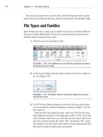
FIGURE 12.83 Click the Set button.
4. Click OK.
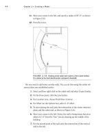
5. Pick the roof, as shown in Figure 12.84.
6. On the Model panel of the Home tab, click the Model Line button.
FIGURE 12.84 Picking the roof. Your work plane is now set to slope with
the roof. Anything you draw will be on this sloping plane.
Creating Blank Drafting Views
645
7. In the Properties dialog under Line Style, click the Medium Lines line
type, as shown in Figure 12.85.
FIGURE 12.85 Click the Medium Lines button under Line Style in the
Properties dialog.
8. On the Draw panel, click the Start-End-Radius Arc button, as shown
in Figure 12.86.
9. Draw an arc from the two endpoints shown in Figure 12.86. Make the
radius 80
′–0″.
10. Go to a 3D view. You can still see the arc.
11. Save the model.
FIGURE 12.86 Drawing an 80′–0″ radius arc
Chapter 12 • Detailing
646
It is a good idea to keep this feature in mind. This drafting tool will become
quite useful when it comes to sketching in 3D. There are going to be many situ-
ations when you use this little nugget!
Are You Experienced?
Now you can…
modify and add line weights to be used in both the 3D and 2D
environment
add linework in a drafting view as well as a 2D and 3D view
create both masking regions and filled regions to provide hatching to
a model
mask an area so you can draft over it
add detail components to the model and create repeating details
modify detail families to suit your needs
create a group to be used in multiple drafting views and change the
group and update each copy in each view
create a new Drafting view to draft from scratch and import a CAD
file into a drafting view
CHAPTER 13
Creating Specific Views
and Match Lines
As you can see, Revit is all about the views. In fact, by using Revit, not
only are you replacing the application you use for drafting, but you are also
replacing your existing file storage system as well. This is largely because we
are now using one model, and we are simply using views of that model for
our project navigation.
Duplicating views
Creating dependent views
Adding match lines
Using view templates
Chapter 13 • Creating Specific Views and Match Lines
648
Duplicating Views
That being said, I wanted to dedicate an entire chapter to project navigation.
Although you have steadily gained experience in this area, we can expand on
much more to round out your Revit expertise.
The first item we will tackle in this chapter is the process of duplicating a view
to create another. Although it is a straightforward procedure, a lot is riding on
the hope that you proceed with this function correctly. As you are about to find
out, this command is not a simple copy-and-paste operation.
Revit will change how you organize a project. You will no longer open a file and
save it as another file so you can make changes without affecting the original.
As you know, Revit is all-inclusive in terms of files. Well, there is only one. From
that one file, there are views that reside within the Project Browser.
Of course I am not telling you anything you have not learned. If you have
gone through the book from page 1, you have already gained experience in cre-
ating views (especially in Chapter 3, “Creating Views”). If you are just jumping
to this chapter, you most certainly have had some exposure to view creation.
The reason this topic is broken into two chapters is to help you gain a more in-
depth understanding of how you can manipulate and organize views.
Now let’s duplicate some views! To begin, open the file you have been follow-
ing along with. If you did not complete the previous chapter, go to the book’s
web page at www.sybex.com/go/revit2011ner. From there you can browse to
Chapter 13 and find the file called
NER-30.rvt.
The objective of the following procedure is to create a furniture plan of Level
1, then turn off the furniture on the original Level 1.
1. In the Project Browser, find the Level 1 floor plan and right-click.
2. Select Duplicate View
➢ Duplicate With Detailing, as shown in
Figure 13.1.
3. You now have a view called Copy of Level 1. Right-click on it in the
Project Browser.
4. Rename it to Level 1 Furniture Plan.
5. Make sure you are still in Level 1. In the Level 1 view window, type
VG. This will bring up the Visibility/Graphics Overrides window.
6. In the Visibility column, deselect Casework, Furniture, and Furniture
Systems.
7. Click OK.
Creating Dependent Views
649
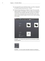
FIGURE 13.1
Right-clicking on the Level 1 Floor Plan in the Project Browser
Now any time you add furniture or casework, it will only show up in the furni-
ture plan. You do not need to deal with a layer or display configuration.
The ability to create a copy of a view and then modify its visibility graphics to
display certain items is a critical function within Revit. Another similar task is
also available: creating coordinated match line divisions in a model by creating
dependent views.
Creating Dependent Views
You create a dependent view in much the same way you duplicate a view. In fact,
you are duplicating a view. The function of a dependent view is to “nest” a dupli-
cate of a view within the host view (or the view you are making the duplicate
of). This nested view is dependent on the host view in terms of visibility graphics
and View Properties. You can have multiple dependent views categorized under
the host view. The reason we create dependent views is to add match lines. Yes,
you could simply duplicate a view and move its crop region, but when you have
dependent views—as you will see in Chapter 14, “Creating Sheets and Printing”
—you can tag those views in a specific way for Revit to keep track of the sheets
they are on. Dependent views also give the advantage of making your Project
Browser much less cluttered, without unnecessary floor plans.
O
The difference
between choos-
ing Duplicate
With Detailing
and Duplicate is
that Duplicate With
Detailing will also
copy all the tags
and annotations you
have in the original
view. Duplicate
will only copy the
geometry.
Chapter 13 • Creating Specific Views and Match Lines
650
The objective of the next procedure is to make a dependent view of the Level 1
Floor Plan.
1. In the Project Browser, right-click on the Level 1 floor plan.
2. Select Duplicate View ➢ Duplicate As A Dependent. You now have
a view that is nested under Level 1. As you can see, Level 1 is now
expanded to show its dependencies.
3. Right-click on Level 1 again.
4. Select Duplicate View
➢ Duplicate As A Dependent. You now have two
views nested under Level 1 (see Figure 13.2).
5. Right-click on the Dependent (2) on Level 1 dependent view.
6. Rename it to Level 1 East.
7. Rename the other dependent view to Level 1 West (see Figure 13.2).
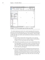
FIGURE 13.2 Creating the two views dependent on Level 1
Now that the views are duplicated and nested within the host view, it is time
to divide the Level 1 floor plan. We will do this by adjusting the crop region.
Adjusting the Crop Regions
Every view in Revit has a crop region. Crop regions play an important role when
your plan is too large to fit on a sheet. All we need to do at this point is to slide
the east and the west crop regions to display the correct views.
The objective of the next procedure is to adjust the crop regions to display the
appropriate parts of the plan based on the name of the views.
1. Open the Level 1 West dependent view.
2. Select the crop region, as shown in Figure 13.3.
Creating Dependent Views
651
3. Drag the right side of the crop region to the position shown in
Figure 13.3.
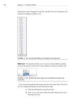
FIGURE 13.3 Dragging the crop region in the Level 1 West view
4. Open the Level 1 East view.
5. Select the crop region.
6. Drag the left side of the region to the right, as shown in Figure 13.4.
st r e t C h th a t vi e W
You will notice that there are two stretch grips. One is for the actual crop
region, and the other is for the annotation crop region. We will cover what
the annotation crop region means in a moment. For now, pick the stretch
grip to the inside as shown in this image:
Chapter 13 • Creating Specific Views and Match Lines
652
FIGURE 13.4 Dragging the crop region to the right
7. Select the crop region again if it is not selected already and right-click.
8. Choose Go To Primary View to open the Level 1 floor plan.
9. When you are in the Level 1 floor plan, turn on the crop region by
clicking the Display Crop Region button on the View Control toolbar,
as shown in Figure 13.5.
FIGURE 13.5 Turning on the crop region from the View Control toolbar
Now you can see the area where you need to draw the match line.
The crop region should overlap in the corridor. If not, drag the crop
regions so that they match Figure 13.6.
NOTE
If you would like to turn a dependent view back to an inde-
pendent view, you can simply right-click on the dependent view and select
Convert To Independent View. This will break the link to the host view.
Unfortunately, if you have a match line situation in your project, you must fol-
low this procedure with each floor plan separately. For multifloor projects, this
can become time-consuming. Or you can right-click on a view that has depen-
dencies, and select Apply Dependent Views. From there you can select which
views the dependent views will be added to.
Creating Dependent Views
653
FIGURE 13.6 Adjusting the crop regions to overlap in the corridor
As you can see, adjusting the crop region is how you specify which part of the
plan is going to show up on your sheet. This poses one issue. If you have text that
you would like to lie outside of the crop region—that is, if you have a leadered
note pointing to an item within the cropped boundary—you may not see the
note. This is where we can adjust the annotation crop region.
Adjusting the Annotation Crop Region
Since the crop region cuts off the model at a specified perimeter, what is to become
of our text that needs to lie outside of this boundary? This is where the annotation
crop region comes in handy. You will always have the situation where leadered text
must be outside of the geometry it is labeling. We can make adjustments to ensure
this can happen.
The objective of the next procedure is to adjust an annotation crop region to
clean up a plan.
1. In the Project Browser, find the Level 1 West dependent view and
open it.
2. Select the crop region, as shown in Figure 13.7. Notice the two perim-
eters: one is a solid line type and the other is a dashed line type.
3. In the corridor, there is a dimension that seems to be floating. This
is because the crop region allows this dimension to show. With the
crop region still selected, pick the outside stretch grip (as shown in
Figure 13.8) and stretch the annotation crop region in until the dimen-
sion disappears.