Autodesk Revit Architecture 2011 No Experience Required - part 74 doc
Bạn đang xem bản rút gọn của tài liệu. Xem và tải ngay bản đầy đủ của tài liệu tại đây (881.42 KB, 10 trang )
Chapter 15 • Creating Rooms and Area Plans
704
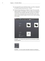
8. Add VCT to Floor Finish (see Figure 15.10).
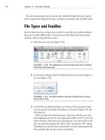
FIGURE 15.9 Hover the cursor over the room until the X appears.
FIGURE 15.10 Adding values to the identity data
Creating Rooms
705
9. Select the SOUTHEAST CONFERENCE room.
10. In the Properties dialog, click into the Base Finish field. Notice there
is a pull-down menu. Click the arrow and select WD-1, as shown in
Figure 15.11.
11. Change the rest of the fields using the previous entries.
12. Save the model.
FIGURE 15.11 Once a field has been added to the database, it is available
for the rest of the rooms.
Changing a room’s properties is a simple task. There is, however, one more
item to discuss. This pertains to a room that spans multiple floors such as the
east entry.
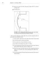
The objective of the next procedure is to change the height of the east entry
room’s properties.
1. Zoom in on the east entry area and select the room, as shown in
Figure 15.12.
2. In the Properties dialog, change Upper Limit to Roof.
3. Change Limit Offset to 0. This will set the east entry room to extend
from Level 1 to the roof.
Now that we have experience changing the properties of the rooms, it is
time to take a look at the properties of the actual walls that divide the rooms.
Certainly you noticed that when you placed the rooms in the lavatories, the
O
If you are having
trouble selecting
the room, remem-
ber, you can pick
an entire window
around the area and
use the Filter button
on the Filter panel.
Chapter 15 • Creating Rooms and Area Plans
706
room did not fill the small entry areas. We can correct this by changing the
wall’s room bounding properties.
FIGURE 15.12 Selecting the east entry room
Room Bounding Properties
By default, each wall you add to the Revit model will automatically define a
room boundary, and this is what we want to see 95 percent of the time. There
are some situations, however, where we do not want a wall to separate the room
itself. In such cases, we can modify the instance parameters of the wall to disal-
low the division of the room.
The objective of the following procedure is to “turn off” the room bounding in
certain walls.
1. In the East Wing floor plan, zoom in on the lavatory area.
2. Select the wall that divides the Men’s toilet area from the Men’s lava-
tory entry area, as shown in Figure 15.13.
Creating Rooms
707
FIGURE 15.13 Selecting the partition within the Men’s lavatory
3. In the Properties dialog, scroll down to the Room Bounding row.
4. Uncheck Room Bounding, as shown in Figure 15.14.
FIGURE 15.14 Unchecking Room Bounding
5. Repeat the procedure in the Women’s lavatory.
6. Save the model.
Having the ability to add rooms and manipulate the information in the Revit
database easily gives you a tremendous advantage as you move forward with the
rest of the model. Also, that information is relayed into the room’s tag, which is
automatically added as you place the room into the model.
Chapter 15 • Creating Rooms and Area Plans
708
This concept brings us to our next topic: how to change the actual tag to dis-
play the information on the drawings that we desire.
Placing and Manipulating Room Tags
As mentioned earlier, the room tag is merely a vehicle to relay the room’s data
to the construction documents. As a default, a room tag is added automatically
as you place the room into the model. A default room tag is included, but we are
not stuck with this room tag.
The objective of the next procedure is to add an alternate room tag to the room,
and to open the tag’s family editor to investigate the composition of the tag.
1. Zoom into the SOUTHEAST CORNER OFFICE.
2. Select the room tag.
3. In the Properties dialog, select Room Tag With Area, as shown in
Figure 15.15.
FIGURE 15.15 Change the type to Room Tag With Area
Now that was just way too easy! Let’s take a closer look at what we just did. A
room tag is nothing more than the cover sheet we created back in Chapter 14,
“Creating Sheets and Printing.” All we need to do is simply open the file, and
place a tag into the family.
Creating Rooms
709
To open the tag’s Family Editor, follow this procedure:
1. Select the room tag for the SOUTHWEST CORNER OFFICE.
2. On the Modify | Room Tags tab, click the Edit Family button.
3. With the family file open, click on the Room Name piece of text that
is visible. (These pieces of text are actually tags.)
4. On the Modify | Label tab, click the Edit Label button.
5. In the Edit Label dialog, the list to the left displays all the parameters
that you can easily add to the room tag (see Figure 15.16). Do not
change anything and click OK.
FIGURE 15.16 A list of available parameters you can add to the room tag
WARNING
If you are modifying the room tag, do yourself and
the rest of your design team a huge favor and inform everyone that you are
in there modifying your company’s standards! If you are the BIM manager,
set the permissions to this network directory accordingly.
6. Close out of this file without saving any changes.
Now that you know what tag Revit uses while placing a room, and how to
manipulate that tag, it is time to tie the tag into something more robust. Since
a tag is just a reflection of the room data, we can add another Revit object that
does the same thing: a room schedule.
Chapter 15 • Creating Rooms and Area Plans
710
Adding a Room Schedule
Up to this point in our careers we have been adding room information twice,
sometimes three times. And why is that? It’s because we had to fill the tag out
in the plan, then fill the same information out in the room schedule. If you were
in the unfortunate situation where you had an enlarged plan, then you added
the information yet again for a third time. Now when you have to change that
information you need to do it in multiple places. Now, I’m not saying that Revit
will end all your problems, but it sure will make life easier!
The objective of the next procedure is to create a room schedule. We will then
finish filling out the room information from the actual schedule, thus saving
time and increasing accuracy.
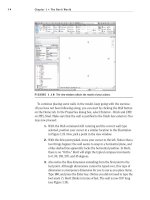
1. On the View tab, click Schedules and then click the Schedule/Quantities
button, as shown in Figure 15.17.
2. In the New Schedule dialog, select Rooms from the list to the left.
3. Click OK.
4. In the Fields tab of the Schedule Properties dialog that opens, add
the following fields in the specified order (see Figure 15.17):
Number
Name
Base Finish
Floor Finish
Wall Finish
Ceiling Finish
Comments
Level
5. Click the Sorting/Grouping tab.
6. Sort by Number.
7. Click OK. Your schedule will look similar to Figure 15.18, with the
probable exception of the Room 0.
Adding a Room Schedule
711
FIGURE 15.17 Adding the fields to the schedule
FIGURE 15.18 The room schedule
Chapter 15 • Creating Rooms and Area Plans
712
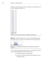
8. With the schedule still open, click into the EAST ENTRY Base Finish
cell, and type WD-2.
tu r n i n g oFF un W a n t e d ro o M s
The schedule in the book has an errant room that does not belong in the
schedule. Because going step by step through a book does not give you a
true feel for a real-world scenario, I can tell you that you will wind up with
some misplaced rooms. This is OK, because you can turn them off in the
schedule. If you click the Not Placed/Not Enclosed menu, you will see that
you can show, hide, or isolate unwanted data. For this example, I will choose
Hide to remove the row (see the following graphic).
9. Click into the Floor Finish cell and type TER (for Terrazzo).
10. Click into the Wall Finish cell and type VINYL.
11. Click into the Ceiling Finish cell and type a hyphen (-).
12. Click into the EAST WING CORRIDOR Base Finish cell. Notice there
is a menu arrow, as shown in Figure 15.19. Click it. You now have a
choice between two base finishes. Choose WD-2.
13. Change the other values to TER, VINYL, and ACT (see Figure 15.19).
FIGURE 15.19 Filling out the room schedule
Now that we have the rooms in place and a schedule filled out, it is time to move
to a more colorful aspect of adding rooms to the model: adding a color fill plan.
Adding a Color Fill Plan
713
Adding a Color Fill Plan
Another benefit of using the Room feature in Revit is that you can add a color
plan at any time, and you can virtually create any type of color scheme or pattern
scheme you desire. And here’s the best part: adding one is so easy it is almost fun!
The objective of the next procedure is to make a duplicate of the East Wing
floor plan and to create a color scheme based on room name.
1. Right-click on the Level 1 floor plan view and select Duplicate View
➢
Duplicate, as shown in Figure 15.20.
FIGURE 15.20 Duplicating the view
2. Right-click on the new view and select Rename.
3. Rename the view to Level 1 Color Plan.
4. Click OK.
5. Open the new plan if it is not open already.
6. In the Room & Area panel of the Home tab, click the Legend button,
as shown in Figure 15.21.
7. After you click the Legend button, you can place the legend into the
model. Place it into the upper-right corner of the view (inside the crop
region), as shown in Figure 15.21.
8. In the Choose Space Type And Color Scheme dialog, change Space
Type to Rooms and Color Scheme to Name (see Figure 15.22).