Autodesk Revit Architecture 2011 No Experience Required - part 82 ppsx
Bạn đang xem bản rút gọn của tài liệu. Xem và tải ngay bản đầy đủ của tài liệu tại đây (509.9 KB, 10 trang )
Chapter 17 • Creating Families
784
li n e is to o sh o r t ?
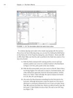
You may get an error at some point as you pick these lines, as shown in the
following image. This is more of a nuisance than anything else. All you need
to do is click OK, delete the line(s) that were set into the wrong spot, and redo
the same command. You will have more success the second time through.
12. Set the offset on the Options bar to 0″.
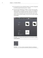
13. Draw a line connecting the bottom of each jamb, as shown in
Figure 17.18.
14. In the Properties dialog, make sure the type is set to Extrusion, as
shown in Figure 17.19.
15. Set Extrusion End to –3
″, as shown in Figure 17.19.
FIGURE 17.18 Picking the frame for the jamb
Using a Complex Family to Create an Arched Door
785
16. Click the small button to the right of the Material row, as shown in
Figure 17.19.
FIGURE 17.19 Clicking the button to add a material parameter
17. Click Add Parameter at the bottom-left corner of the dialog.
18. Name it Jamb Material.
19. Group it under Materials And Finishes.
20. Keep it a Type parameter.
21. Click OK.
22. Notice the Material field is no longer active. Click OK again.
What did we just do? By not selecting the actual material in the properties
of the extrusion, we created a parameter so users could specify whatever mate-
rial they deemed necessary. This is a valuable step in family creation. It’s called
flexibility.
Speaking of flexibility, this jamb is held at a steady 3″. This is an incorrect value
and will remain static unless we do something about it. We will do so right now.
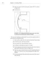
The objective of the next procedure is to align the inside face of the jamb with the
inside face of the wall and to lock that alignment in place.
1. Go to a 3D view, and make sure you are “spun around” so you can see
the inside face of the wall where the jamb does not align.
2. Click the Align button, as shown in Figure 17.20.
Chapter 17 • Creating Families
786
3. On the Options bar, select Wall Faces for Preference.
4. Pick the inside face of the wall.
5. Pick the inside face of the jamb.
6. Click the open padlock icon that appears (see Figure 17.20).
7. Press Esc.
8. Click the Save icon.
9. Save the door into a directory where you will be able to find it.
10. Call it Arched Door.rfa.
11. Make sure your project is open.
12. In the
Arched Door.rfa file, click Load Into Projects.
13. In the model, open the Level 1 West dependent view.
14. On the Home tab, click the Door button.
15. Insert it in the wall, as shown in Figure 17.21. (Do not worry too much
about placement.)
16. Select the door.
FIGURE 17.20 Aligning and locking the inside face of the jamb to the wall
Using a Complex Family to Create an Arched Door
787
FIGURE 17.21 Adding the family to the project
17. In the Properties dialog, click Edit Type and observe the parameters.
Look familiar? You created them!
18. Click OK.
19. Go back to the door family.
Wow! So this thing actually works. Good deal. The next trick is to add some
casing to the outside of the frame. To do so, we will have to use a solid sweep.
Creating a 3D Sweep within a Family
Going along the same lines (literally) as the extrusion, we can create a situation
where we actually sketch a path and extrude a profile along that path. The trick
is to make sure that this sweep can flex along with the door.
The objective of the next procedure is to create the door casing by using a
3D sweep.
1. Go to a 3D view (if you are not there already) and position the view so
it looks like Figure 17.22.
2. On the Home tab, click the Sweep button.
3. On the Sweep panel, click the Pick Path button.
4. Pick the inside corner of the jamb starting with the left side, as
shown in Figure 17.22.
Chapter 17 • Creating Families
788
5. Click Finish Edit Mode on the Mode panel.
6. On the Sweep panel, click the Load Profile button.
7. Go to the
Profiles folder and select Casing Profile-2.rfa.
8. Click Open.
9. In the menu on the Sweep panel, click the Profile drop-down and
select Casing Profile 2:5 1/2″ × 3/16″ (notice the red dot is now
replaced with the actual profile).
10. On the Options bar, type –0’–5 3/4” for the Y offset. Notice the profile
is pushed back onto the wall with a 1/4
″ reveal.
11. Click Finish Edit Mode.
12. In the Properties dialog, click the small button to the right of the
Material category.
13. Click Add Parameter.
14. Call the parameter Casing Material.
15. Group it under Materials and Finishes.
16. Click OK twice.
17. Repeat steps 1 through 20 on the other side of the door. (Do not try
to mirror it. It will not work.)
FIGURE 17.22 Picking the path for the sweep
Using a Complex Family to Create an Arched Door
789
18. Save the family.
19. Load it into the project.
20. In your model, select the door.
21. In the Properties dialog, click Edit Type.
22. Change the Width value to 3
′–0″.
23. Click OK.
Your door is still working properly and is looking better as shown in Figure 17.23.
FIGURE 17.23 The finished sweep
Let’s move forward and start working on adding a door to the family. The big-
gest challenge here will be the plan swing representation, but with a few new
items to learn, this will be no problem.
The objective of the next procedure is to add a door, a stop, and some plan
symbolic linework.
1. Open the door family.
2. Go to the exterior elevation.
3. On the Home tab, click the Extrusion button.
Chapter 17 • Creating Families
790
4. On the Draw panel, click the Pick Lines icon.
5. Set the offset to 1/8
″.
6. Offset the two sides and the radial top to the inside 1/8
″.
7. Set the offset to 1/2
″.
8. Offset the bottom up (see Figure 17.24).
9. Trim the bottom corners so the door is one panel.
FIGURE 17.24 Adding the door
10. In the Properties dialog, make sure Extrusion is current in the
Type menu.
11. For the Extrusion end, type -1 3/8”.
12. For the material, click the button to the right of the Material field,
and add a new parameter called Door Material.
13. Categorize it under Materials And Finishes.
14. Click OK.
15. Click Finish Edit Mode.
16. In the Project Browser, go to the Ref. Level floor plan view.
17. Click the Thin Lines button on the View tab, as shown in Figure 17.25.
You door should look like this figure.
18. Load the door into your project. (Click Yes to overwrite the door that
is there.) Verify that the door looks correct.
Using a Complex Family to Create an Arched Door
791
FIGURE 17.25 The finished door in plan
Now that you have created the door, it is time to fix up the plan view. What we
need to do is add a door swing. Also, we don’t want to see the door panel in plan,
so we can create a view state to turn it off in the plan view.
The objective of the next procedure is to create a door swing and to make the
door panel invisible in plan.
1. On the Annotate tab, click the Symbolic Line button, as shown in
Figure 17.26.
FIGURE 17.26 The Symbolic Line button
Chapter 17 • Creating Families
792
2. Draw a line straight up from the right corner of the jamb (on the
exterior side of the wall) 4
′–0″, as shown in Figure 17.27.
3. Draw another line to the right 1 3/8
″.
4. Draw another line straight down 4
′–0″.
5. Draw another line to the right 1 3/8
″ (see Figure 17.27).
6. Click the Symbolic Line button again.
FIGURE 17.27 Drawing the symbolic door swing
7. Draw an arc from the left side of the jamb to the top of the symbolic
swing, as shown in Figure 17.28.
FIGURE 17.28 Drawing the plan swing arc
Creating an In-Place Family
793
With the plan swing in place, we can now turn off the actual door panel. This
process is quick and painless!
1. Select the door panel.
2. On the Modify | Extrusion tab, click the Visibility Settings button on
the Mode panel.
3. Uncheck Plan/RCP.
4. Uncheck When Cut In Plan/RCP (If Category Permits).
5. Click OK.
6. Save the family.
7. Load it into the project. If it didn’t explode, your door is complete!
As you can see, it is not all that difficult to create a family. This topic could be a
book within a book. Start experimenting with your own families. If you run into
a snag, send me an email at , and we can work on it.
The next type of family we will study is one that literally can’t be avoided.
Eventually you will need the surrounding geometry of the model to create the
family. This is called an in-place family.
Creating an In-Place Family
An in-place family gives you the best of both worlds. When you start the In-Place
Family command, your model turns into the Family Editor. You can make a fam-
ily exactly the same way you just did, except that it is native to the model. Many
times you will need this flexibility when you have a family you will never use
again in any other building. This also gives you the flexibility to create custom
content that cannot be created using the conventional Revit commands.
To create an in-place family, follow along with this procedure:
1. Open the model you have been working on.
2. Open the section view called West Wing South Wall Section.
3. On the Home tab, click Component
➢ Model In-Place, as shown in
Figure 17.29.
4. Set Family Category to Doors; then click OK.
5. Call the new door West Opening.
6. Click OK.