Autodesk Revit Architecture 2011 No Experience Required - part 92 pptx
Bạn đang xem bản rút gọn của tài liệu. Xem và tải ngay bản đầy đủ của tài liệu tại đây (662.81 KB, 10 trang )
Chapter 21 • Phasing and Design Options
884
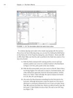
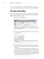
7. In the Phasing dialog, click the Phase Filters tab. Notice this tab
contains the filtering you are using in this project. You can add or
modify these filters at any time (see Figure 21.19).
8. In the Phasing dialog, click the Graphic Overrides tab. Here you can
see that you can change the line types and the shading for each phase
status (see Figure 21.20). Click OK.
FIGURE 21.18 The Show Complete phase filter
FIGURE 21.19 Phase filters
Examining Phase Filters
885
FIGURE 21.20 Graphic Overrides tab
Typically in a set of drawings, you are not going to have a show complete view,
but it can be extremely helpful with internal coordination throughout the life of
the project. You can quickly see where major deficiencies happen when you view
a model as completed.
One problem with all this phasing is that, on some projects, your Project
Browser will become confusing and crowded quickly. Let’s look at dividing the
browser up into phases.
1. In the Project Browser, right-click on the Views (Discipline) heading,
as shown in Figure 21.21, and click Properties.
FIGURE 21.21 Opening the browser’s properties
2. Click the Edit button in the Folders row.
O
Phase filters are
great, but don’t go
crazy with them. You
can easily create more
confusion than good.
Chapter 21 • Phasing and Design Options
886
3. You will see that the browser is already organized by Discipline. Focus
on the Then By section, and change the Then By category to Phase (as
shown in Figure 21.22).
4. Click OK twice to get back to the model.
Well, I think you can see that browser organization can help you organize a
project. Be careful, though. Adding random, multiple categorizations could get
out of hand and wind up more confusing than if you had just left the Project
Browser alone.
FIGURE 21.22 Changing Then By to Phase
Wh a t t h e “???” in t h e pr o j e C t br o W s e r Me a n s
What the heck is that? As you can see in the following graphic, there are
three question marks in our Project Browser. This will happen when you
start organizing the browser by a specific property that some views do not
contain. The views categorized in the ??? heading are drafting views, and
they do not have a phase property.
Creating Design Options
887
Another functionality of Revit that we need to venture into is similar to phas-
ing, but has an entirely different meaning when it comes to tracking aspects of a
project. This functionality is called design options.
Creating Design Options
Revit is equipped with the functionality to allow you to model different options
in one model, better known in the design world as bid alternates. The great thing
about how Revit handles this functionality is that any alternate design will never
be (or at least will seldom be) a completely new structure. There will be items
that are in more than one option. Revit allows you to keep like items intact while
creating new or different items that belong to different options. This creates a
situation where you only need to model the common items once, so you can
focus on the alternates.
That being said, there is a lot to be added to this functionality. Many of the
examples in this section of the chapter will deal more with flaws in Revit than
with actual design option procedures.
To get started, go to the book’s website at www.sybex.com/go/revit2011ner.
From there you can browse to Chapter 21 and find the file called
NER-38.rvt.
Follow along with the procedure.
1. On the Manage tab, click the Design Options button, as shown in
Figure 21.23.
2. In the Design Options dialog, click the New button under Option Set.
NOTE
You can have as many option sets as you choose. There will be
cases where you have other, unrelated options in other places in your model.
FIGURE 21.23 Clicking the Design Options button
Chapter 21 • Phasing and Design Options
888
3. Select Option Set 1.
4. In the Option Set category, click the Rename button.
5. Call the option set West Entry.
6. Select Option 1 (Primary).
7. In the Option category, click Rename.
8. Rename it to With Entrance.
9. In the Option category, click the New button.
10. Rename the new option Without Entry (see Figure 21.24).
FIGURE 21.24 Adding options
11. Click Close.
12. In the Project Browser, go to the Level 1 floor plan.
13. Select the curtain wall to the left of the entry, as shown in
Figure 21.25.
14. Click the Cut to Clipboard button, as shown in Figure 21.25.
15. Delete the door family in the middle of the wall.
Creating Design Options
889
FIGURE 21.25 Cutting the curtain wall out of the host wall
TIP
If you have a lot of in-place families, you are going to have an
extremely difficult time with design options. When you know you might have
design options, create all your families outside the model.
16. Select the walls as shown in Figure 21.26, and click the Add To Set
button in the Design Options panel on the Manage tab. (You will have
to click the Manage tab.)
17. In the Add To Design Option Set, only check With Entrance
(Primary), and click OK.
18. Select the floor.
19. Click the Add To Set button.
20. Add the floor to both options. (Keep both items checked.) Click OK.
21. Go to a 3D view.
22. Select the curtain walls and the roof. (Use your filter and only check
Curtain Systems and Roof.)
23. Click Add To Set.
24. Add the curtain walls and the roof to the With Entrance (Primary)
option only, and click OK.
Chapter 21 • Phasing and Design Options
890
FIGURE 21.26 Adding the walls to the option set
Phew! Let’s take a breather! The next thing we need to do is put that curtain
wall back into the model. To do this, we need to make the option we want this wall
to be in current. It is almost like making a layer current in AutoCAD.
To start placing objects in a specific option, follow along with these steps:
1. On the Design Options panel of the Manage tab, click the Active
Design Option menu, and select With Entrance (Primary), as shown
in Figure 21.27. (This that you are making this option current.)
FIGURE 21.27 Making the design option current
2. On the Modify tab, click Paste Aligned ➢ Same Place. Your curtain
wall is back in action.
3. Go to the Level 1 floor plan.
Creating Design Options
891
4. On the Design Options panel, select the Without Entry option.
5. Select the floor, and click the Edit Boundary icon on the Modify |
Floors tab.
6. Eliminate the jog in the floor, leaving only a straight line.
7. Click Finish Edit Mode, and click No for the next two questions.
8. On the Home tab, click the Wall button.
9. In the Change Element Type dialog, select the Exterior - Brick And
CMU On MTL. Stud (No Parapet) wall type.
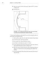
10. Draw a wall across the front of the building, as shown in Figure 21.28.
FIGURE 21.28 Drawing a new wall across the front of the building
is th a t Wa l l no t Wo r k i n g ou t ?
At the ends of the walls, you may run into a join situation. If this is the case,
be sure to set wall joins to Mitered.
11. Go to a 3D view. Attach the wall to the roof.
Notice that the foundation and the pad are causing trouble. You
can add these items to the current option as well. To do so, return to
the previous exercise.
12. Click the Active Only button off at the bottom of the screen, as shown
in Figure 21.29.
13. Select the entire site, including plantings and walkways, and click
Hide In View
➢ Category.
Chapter 21 • Phasing and Design Options
892
14. Select the five foundation walls under the entry and the long wall,
and add them to the set.
15. Go to the T.O. Footing Structural Plan.
16. Change Option to Without Entry.
17. Draw a new foundation wall and add a footing to it.
FIGURE 21.29 The Active Only button
18. Go to a 3D view.
19. Change Current Option to None.
Now that the options are set, we can toggle the views to reflect the option we
desire. To do so, we will create a duplicate view and have two different option
sets for a 3D view.
1. In the Project Browser, right-click on the {3D} view, and duplicate it.
2. Call the new view West Entry - With Entry.
Creating Design Options
893
3. Duplicate the view again, and rename the second view to West Entry -
Without Entry.
4. Open the West Entry - Without Entry view.
5. Type VG.
6. On the Design Options tab, select Without Entry from the Design
Option menu, as shown in Figure 21.30.
7. Open the West Entry - With Entry view, and change the option to
With Entry.
FIGURE 21.30 Choosing the correct option
Your options are set. Do not expect to have a graceful experience with this the
first time you venture into design options. However, once you get the technique
down, you will start to see the advantages of using this feature.