Introducing 3ds Max 9 3D for beginners apr 2007 - part 8 pdf
Bạn đang xem bản rút gọn của tài liệu. Xem và tải ngay bản đầy đủ của tài liệu tại đây (1.92 MB, 55 trang )
After the biped is fit snugly to the model, you will select all of the components of the
model, not the biped, and apply the Physique or Skin modifier in a process often referred
to as skinning. The Physique modifier dictates which object, the pelvis of the biped usually,
the model is applied to and it is the node where modifications to the skin are accessed. It
may take a while to properly test and refine the relationship between the model and the
biped to get it to an acceptable level.
The final step will be to animate your character. You can accomplish this by using a
combination of adding walk, run, and jump cycles to the biped, applying freeform anima-
tion, and refining the animation keys in the Dope Sheet. Don’t expect the default walk,
run, and jump cycles to create realistic motion. They are just a starting point and must be
tweaked to achieve acceptable movements. Character animation is about nuance and sub-
tlety, and those artistic touches take a significant amount of time and effort to master.
The best way to start is to jump in and examine the tools available. In the next section,
you will work with a biped and adjust the parameters and components to modify it.
Creating a Biped
As stated previously, you should create your model first and then create and modify your
biped to fit the model. In this section, however, you are going to examine the procedure
for creating and modifying a biped first to provide an understanding of its capabilities.
Later in this chapter, we will revisit the methods for adjusting your biped specifically to
match a model.
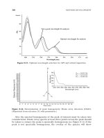
Figure 9.2
The default biped
Figure 9.1
A bipedal character in the reference position
368 ■ chapter 9: Character Studio and IK Animation
97612c09.qxd 2/26/07 3:00 PM Page 368
Placing a Biped in a Scene
Let’s create a Biped system for your scene to get a feel for how CS works. Unlike many
of the objects that you’ve created so far, Biped is located under the Systems category
the Create tab of the Command panel rather than the Geometry button.
Follow these steps to create and adjust a biped:
1. From the Command panel, select Create
➔
Systems
➔
Biped.
2. Click and drag in the Perspective viewport to create the biped.
Clicking sets the insertion point, and dragging defines the height
of the biped system and defines all of the components. All of the
biped’s components are sized relative to the biped’s Height parame-
ter. Instead of making a single object, you created 30 visible and 5
hidden objects arranged in a linked hierarchy. All of the elements
on the left side of the biped’s body will be blue, and all
of the elements
on the right side will be green.
This is part of the Character Studio col-
oring scheme that is carried throughout 3ds Max.
3. Press the H key to see the list of visible objects created with the
default biped. All of the objects are indented from the edge of the
dialog box, indicating that they are subordinate to, or children
of, the objects above them in the list. Close the Select Objects
dialog box.
If your Select Objects dialog box does not display a hierarchy in an indented format as
shown, check the Display Subtree box near the bottom of the dialog.
creating a biped ■ 369
97612c09.qxd 2/26/07 3:00 PM Page 369
4. While the biped is still selected, scroll the Command panel to display the Create Biped
rollout.
This rollout is where changes to the biped’s structure are made. You can increase
the number of fingers and toes and the number of links in each to match your
model. You can even add a tail or ponytails by increasing the number of links for
these parameters, or you can discard the arms altogether. Adding neck links will
make your biped taller, but adding spine links will only subdivide the torso area for
more control in the midsection.
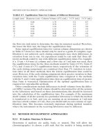
5. Change the parameters as you like. The biped in Figure 9.3 includes additional fingers
and toes, as well as a tail and a ponytail.
Figure 9.3
A biped with modi-
fied parameters
The root object of the hierarchy is named Bip01, for the first biped that you create in a scene,
and all the associated objects will have a Bip01 prefix. Changing the name of the object in the
Name and Color rollout changes only the name of the root object and does not cascade
throughout the hierarchy. Changing the name in the Root Name section of the Create Biped
rollout, however, affects all of the objects in the biped.
370 ■ chapter 9: Character Studio and IK Animation
97612c09.qxd 2/26/07 3:00 PM Page 370
Modifying a Biped
Bipeds are very generic in appearance, and you will rarely, if ever, use the default biped in
an actual animation. Biped’s have a complete set of tools available for modifying their
structure and their behavior to match a model. You will have to select an appropriate edit-
ing mode to access the appropriate tools to adjust your biped. This section covers the tools
used to adjust the size of a biped’s individual elements.
1. Clear your selection set by clicking the Select Object ( ) button in the main toolbar
and then clicking on any blank area of a viewport. Nothing in your scene should be
selected.
2. Click any part of your biped to select it. Bipeds react differently than other objects:
selecting any single component opens the entire object for editing.
3. Click the Modify tab of the Command panel. The purpose of a biped is to create
an animation. This is why all of the biped’s parameters, including those that control
animation and appearance, are consolidated under the Motion tab of the Command
panel.
4. Click the Motion tab of the Command panel to display the first level of rollouts to
control a biped.
5. In the Biped rollout, click the Figure Mode button to display
the rollouts that pertain to the biped’s configuration, but
not to its animation or footstep control. The Figure Mode
button turns blue to indicate the current mode that the
system is using.
6. Expand the Structure rollout to access the same parameters
that were used when you first created the biped to adjust its
basic configuration. Make any additional modifications that
you choose.
7. Select the biped’s left upper arm. In the main toolbar, click the Rotate transform but-
ton and set the reference coordinate system to Local. Most transforms that are applied
to a biped are applied in the Local coordinate system so
they are relative to the object, rather than the world or
the current viewport.
In the Body Type area at the bottom of the Structure rollout, you can change the overall
appearance of the biped from the default Skeleton to Male, Female, or Classic. The body
type has little to do with the biped’s capabilities and is more a matter of preference.
creating a biped ■ 371
97612c09.qxd 2/26/07 3:00 PM Page 371
8. Place your cursor over the green Y-axis ring of the Rotate Transform gizmo and drag
upward to rotate the upper arm upward, as shown in Figure 9.4. All of the pivot points
for the biped elements will be placed at the top of the objects. For example, the upper
arm pivots at the shoulder, the lower arm pivots at the elbow, and the hand pivots at
the wrist. This is one of Character Studio’s great time savers.
9. Click the Scale transform in the main toolbar. The reference coordinate system
automatically switches to Local and then grays out to indicate that the parameter
cannot be altered. All scale transforms applied to
biped components must be applied in the Local
reference coordinate system.
10. Click and drag on the X-, Y-, and Z-Axis handles of the Scale Transform gizmo indi-
vidually. The Y and Z handles make the upper arm large or small, causing your biped
to get bulked up or thinned out. Dragging on the X handle changes the length of the
upper arm. You should observe the changes in all of the viewports while you’re
adjusting the scale.
11. Select and adjust the left lower arm, hand, and fingers to suit yourself. Don’t worry
about the right side yet; it will be covered shortly.
372 ■ chapter 9: Character Studio and IK Animation
97612c09.qxd 2/26/07 3:00 PM Page 372
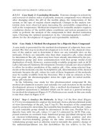
12. Select each of the spine links and scale them to give your biped a nice, tapered torso.
Dragging the X handle upward will scale the links vertically and push the elements
above them upward, increasing the height of the biped. Scaling the top spine link in
the positive Z-direction will push the clavicles and all other arm components out-
ward, as shown in Figure 9.5. The clavicles are linked to the middle of the top spine
link and can be protruded by that link. If necessary, scale the clavicle to extend
beyond the top spine link.
Figure 9.5
Scaling the top
spine link pushes
the arms outward.
Figure 9.4
Rotating a biped
component
creating a biped ■ 373
97612c09.qxd 2/26/07 3:00 PM Page 373
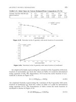
13. Select and scale the pelvis to spread the hips out further.
14. Similar to Steps 10 and 11, use the Scale transform to adjust the scale of the bipeds left
upper and lower leg and foot.
As you can see, creating a biped is fairly simple. You simply click and drag to place the
system and drag to set its height and proportionate size. You then adjust the parameters of
the structure in the Motion panel. Finally, you position and adjust the size of each of the
biped’s components using the transforms.
Copying and Pasting Postures
Most characters are basically symmetrical with some variation in their surface appearance
to make them look a bit less than perfect and a bit more natural. Character Studio allows
you to set the structure and form—called the posture—for elements on one side of a biped’s
body and then paste those features to the elements on the other side. For instance, when
the length, width, and pose of the left arm, hand, and fingers are tweaked as required, the
same dimensions and orientations can be pasted to the same components on the right
side. You don’t need to model the opposite side independently. There is no self-adjusting
relationship between the two sides, so any future changes to one side must be pasted again
to the other to maintain any symmetry.
1. Continue with the previous exercise or open
CSBiped1.max from the companion CD.
2. Select the biped and access Figure mode if necessary.
374 ■ chapter 9: Character Studio and IK Animation
97612c09.qxd 2/26/07 3:00 PM Page 374
3. Double-click on the left upper arm. Double-clicking on an object selects that object
and all the objects below it in the hierarchy—in this case, the lower arm, hand, and all
finger joints.
4. Open the Copy/Paste rollout.
5. Postures must be saved as collections prior to being pasted. Click the Create Collection
button and then rename the collection from the default Col01 to Left Arm.
6. Just below the blue Posture button, click the Copy Posture button to copy the selected
posture to the clipboard. A preview of the copied posture will appear in the Copied
Postures area of the Command panel.
7. Click the Paste Posture Opposite button. The size, scale,
and orientation of the selected objects will be applied to
the reciprocal objects on the opposite side of the biped,
as shown in Figure 9.6.
8. Repeat Steps 3 through 7 to copy the posture of the left leg to the right side of the
biped.
Copied postures are not limited to being pasted within a single biped; they can also be
pasted to other bipeds. Simply copy the posture, select any part of another biped, and then
click the Paste Posture button.
creating a biped ■ 375
97612c09.qxd 2/26/07 3:00 PM Page 375
As you’ve seen in this section, modifying a biped’s appearance and posture is simply
the process of selecting one of its components and using the Rotate and Scale transforms
to change its size and orientation as needed. In the “Associating a Biped to a Character”
section, later in this chapter, you will explore the procedures for fitting a biped to a spe-
cific model to ensure a smooth animation setup. Now is a good time to save your scene
before you proceed to the next section.
Animating a Biped
Bipeds can be animated in several ways, including footstep-driven animation and freeform
animation. Just as it sounds, footstep-driven animation is the process of adding visible foot-
steps to your scene and directing the biped to step onto those footsteps at a particular
point in time. Footsteps can be added individually or as a set of walk, run, or jump steps;
they can be moved or rotated to achieve the desired result. When using footstep-driven
animation, the legs and feet of the biped are not the only things animated; the hips, arms,
tails, and all other components are animated too. A short animation sequence can gener-
ate hundreds, or even thousands, of animation keys.
Footstep-driven animation is often a good starting point, but it is rarely the complete
solution to your animation needs. For example, there is no method for turning a biped’s
head or raising its arms using footsteps. Even when footsteps are used to create the initial
movement of a biped, freeform animation is used to augment and tweak it. Freeform ani-
mation is created using the procedures discussed in Chapter 8, “Introduction to Animation,”
which includes using the Auto Key method and the Track View in Curve Editor mode.
Figure 9.6
Pasting a posture
to the other side
of a biped
376 ■ chapter 9: Character Studio and IK Animation
97612c09.qxd 2/26/07 3:00 PM Page 376
The animation keys that are added to the selected objects appear in the Track Bar where
they can be moved, modified, or deleted to adjust the animation. Some character animators
forgo footstep-driven animation altogether and use freeform animation exclusively for the
control it gives by creating keys only where the animator chooses and not throughout the
biped. In this section, you will explore both the footstep-driven and freeform methods for
animating a biped.
Moving the Biped into Place
As a system, bipeds can’t simply be moved using the Move transform in the Main toolbar.
To position one correctly, you must select and move the root object using the Body Verti-
cal and Body Horizontal buttons.
1. Continue with the previous exercise or open
CSBiped2.max from the companion CD.
If you open the CD file, select the biped and enter Figure mode if necessary.
In the previous exercise, when you scaled either of the leg elements along the X-axis,
the feet of the biped moved off the construction plane where new objects are created.
This plane is where the new footsteps will be placed, so you will want the biped’s feet
at that same elevation.
2. Maximize the Right viewport and zoom so that you can see the dark, horizontal line
indicating the construction plane, the feet, and the pelvis. The pelvis isn’t really
important at this point, but the root object located inside of it is.
animating a biped ■ 377
97612c09.qxd 2/26/07 3:00 PM Page 377
3. In the Track Selection rollout, click the Body Vertical button. This selects the diamond-
shaped Bip01 object, which is the root of the hierarchy, and activates the Move
transform.
4. Use the Move Transform gizmo to move the biped until the feet rest on the construc-
tion plane, as shown in Figure 9.7.
5. Switch back to a four-viewport display.
Adding Footsteps
Adding footsteps is as simple as adding a specified number of steps with a specific gait or
clicking the mouse button to place footsteps individually. First, you will place a series of
steps, and then you will place steps individually.
1. With the biped selected, click the Footstep Mode button in the Biped rollout. The
rollouts change to display the tools for adding and controlling a biped’s motion. The
Footstep mode and Figure mode are exclusive; you cannot be in both modes at the
same time.
2. In the Footstep Creation rollout, make sure that the Walk
gait is selected and then click the Create Multiple Foot-
steps button.
Figure 9.7
Moving the biped to the construction plane
378 ■ chapter 9: Character Studio and IK Animation
97612c09.qxd 2/26/07 3:00 PM Page 378
3. In the Create Multiple Footsteps dialog box that appears, assign the Footstep proper-
ties including the number of steps, the width and length of each step, and which foot
to step with first. Set the Number of Footsteps to 8 and leave the other parameters at
their default values, as shown in Figure 9.8. Click the OK button.
4. Zoom out in the Perspective viewport to see the footsteps that have been created.
Look at the Time slider, and note that the scene now ends at frame 123; that’s 23
more frames than the 100 frames the scene had at the beginning of this chapter. 3ds
Max recognized that it would take the biped 123 frames, just over 4 seconds, to move
through the eight steps that it was given.
Figure 9.8
Creating multiple
footsteps
animating a biped ■ 379
97612c09.qxd 2/26/07 3:00 PM Page 379
5. Click the Play Animation ( ) button in the Playback Controls area. Nothing will
happen. The biped must be told explicitly to create animation keys for the steps that
have been added to the scene.
6. Drag the Time slider back to frame 0.
In the Footstep Operations rollout, click the Create Keys for Inactive Footsteps
button.
The biped will drop its arms and prepare to walk through the footsteps that are now
associated with it.
8. Click the Play Animation button again. This time the biped will walk through the
footsteps with its arms swinging and its tail and ponytail swaying back and forth.
Controlling the View
Now the problem is that the biped walks off screen so you cannot see the end of the walk
cycle. Motion cycles can be very linear and difficult to track, so Character Studio contains
the In Place mode to follow a biped’s animation. While in the In Place mode, the biped
will appear to stay in place while the scene moves around it. The In Place mode cannot be
used in a Camera viewport.
1. In the Biped rollout, click the Modes and Display text with the plus sign to the left of
it. This is actually a small rollout located inside of another rollout that expands to dis-
play additional display-related tools.
2. In the Modes and Displays rollout, click the In Place Mode button.
3. Click the Play Animation button again. This time the biped will appear to be walking
in place while the footsteps move underneath it, as shown in Figure 9.9.
4. Stop the animation playback.
Using the In Place mode helps work out the way a character moves without having to
navigate throughout 3D space with your viewport. It is important to closely watch the
cycle movement and try to finesse parts to suit the character. The In Place mode is great
for this because the viewport moves with the character in 3D space and you can concen-
trate on how its body is moving.
WALK, RUN, OR JUMP?
What is the difference between a walk, run, or jump gait in 3ds Max? The difference is not
speed or length of stride; it’s the number of feet that the biped places on the ground at any
given moment. In a walk gait, the biped has either one foot or both feet on the ground at all
times. During a run sequence, the biped has either one foot on the ground or, in mid stride,
zero feet on the ground. When the biped is executing a jump sequence, it has either both
feet on the ground or zero feet on the ground while it is airborne.
380 ■ chapter 9: Character Studio and IK Animation
97612c09.qxd 2/26/07 3:00 PM Page 380
Adding a Run and Jump Sequence
Having created a footstep cycle doesn’t limit you to just those footsteps. Any extra foot-
step sequences can be added to a biped. These new footsteps are appended to any existing
footsteps. This, in turn, extends the length of the animation, if necessary, to accommodate
the additional footsteps. In the next exercise, you will add footsteps to the existing anima-
tion cycle.
Continue with the previous exercise or open
CSBiped3.max from the companion CD,
select any biped component, and access Footstep mode from the Motion panel.
1. Click the Run button ( ) in the Footstep Creation rollout. This will apply a run gait
to any footsteps created in the Create Multiple Footsteps dialog box.
2. Click the Create Multiple Footsteps button to open the Create Multiple Footsteps
dialog box.
3. Change the Number of Footsteps to 10 and click the OK button.
4. In the Footstep Operations rollout, click the Create Keys for Inactive Footsteps but-
ton to associate the new footsteps with the biped.
5. Press the Play Animation button. The biped walks through the first eight steps and
then runs through the next ten. As you can see, the run sequence meets the definition
of a run, but it is far from realistic. You’ll learn later in this chapter how to add to or
modify a biped’s motion.
6. Click the Jump button in the Footstep Creation rollout, and then click the Create
Multiple Footsteps button.
Figure 9.9
The biped does
not change position
in the viewport
when it is in the In
Place mode.
animating a biped ■ 381
97612c09.qxd 2/26/07 3:00 PM Page 381
7. In the Create Multiple Footsteps dialog box, set the Number of Footsteps to 4 and
click the OK button. Because a jump is defined as a sequence with either two feet or
zero feet on the ground at a time, four jump steps will equal two actual jumps.
8. Click the Create Keys for Inactive Footsteps button to associate the new jump foot-
steps with the biped.
9. Press the Play Animation button. The biped will walk, run, and then end the sequence
with two jumps.
Adding Freeform Animation
Good animation rarely comes from a first try. When you set your keys initially, you will
need to edit them to suit good timing and form, as well as fix any issues that may come up.
Character animation is relational: when one part of the body is in one movement, another
part of the body is in an accompanying or supportive or even opposite form of movement.
When you are walking and your right leg swings forward in a step, your right arm swings
back and your left arm swings out to compensate. With character work, you have to remain
cognizant of the entire body of the character and how it moves.
As with everything that is automated, the walk, run, and jump cycles that CS creates
definitely need some work before they will be acceptable as good animation; they definitely
lack the human touch, which is the earmark of good animation. For example, based on a
standard CS cycle, the biped’s head never turns, the torso is very stiff, and the arms swing
similarly regardless of the gait type selected. With animating using CS, you will need to add
the little nuances of movement that make animation interesting and personable. You will
need to add animation to the biped to gain personality. Luckily, you can easily add or mod-
ify the biped’s existing animation keys with freeform animation using the Auto Key but-
ton and the Dope Sheet. The following exercises contain examples of freeform animation.
Moving the Head
Any character’s head will move along while the character walks. The following steps will
guide you through the process of creating head movement for your biped. Continue with
the current project or open the CSBiped4.max file from the companion CD.
1. Select one of the biped’s components and, if necessary, exit the Footstep mode by
clicking the Footstep Mode button.
The Actual Stride Height parameter in the Create Multiple Footsteps dialog box determines
the height difference from one footstep to the next. For example, to animate your biped
walking up a flight of stairs, you would set the Actual Stride Height to the same value as the
rise of each stair.
382 ■ chapter 9: Character Studio and IK Animation
97612c09.qxd 2/26/07 3:00 PM Page 382
2. Drag the Time slider to frame 50, approximately the point when the biped lifts its left
foot off of footstep number 2.
3. Select the biped’s head and note the animation keys that appear in the Track Bar, as
shown in Figure 9.10.
4. In the Track Bar, select the two keys on either side of the current frame and
delete them.
5. Click the Auto Key button ( ) to turn it on.
Figure 9.10
Selecting a
component of
the biped reveals
all of that object’s
animation keys in
the Track Bar.
There seems to be an intermittent bug in release 9 of 3ds Max. If the selected keys for the
head will not delete, enter and exit the Footstep mode and then try again. They should disap-
pear after the second try.
Footsteps are numbered, starting with the number 0 and initially alternating from the left to
the right side. They are also color-coded, corresponding to the biped, with blue footsteps on
the left and green footsteps on the right.
animating a biped ■ 383
97612c09.qxd 2/26/07 3:00 PM Page 383
6. Click the Rotate transform button and rotate the head to the left and up, as if it sees
somebody in a second floor window off screen. A new key will be created at frame 50,
recording the time and value of the head’s rotation.
7. Scrub the Time slider back and forth. Watch the head rotate from a neutral position
to the orientation that you created and then rotate back to the neutral position.
8. Select all the keys after frame 50 and before frame 100. Delete them by pressing the
Delete key. This will make room for the new key that you are about to create. If ani-
mation keys are too close together, the animation could appear jerky.
9. Select the key at frame 50, hold the Shift key down, and drag a copy of the key to
frame 90. Use the readout at the bottom of the 3ds Max window to drag the key with
precision. Copying the key will cause your biped to hold that neck pose for 40 frames
or about one and one-third seconds. Scrub the Time slider to review the animation.
10. Select the biped’s left upper arm.
11. In the Track Bar, select and delete all keys between frames 50 and 100. The animation
keys for the arms define their swing motion and the biped walks. If you scrub the Time
slider or play the animation, the biped will hold its arm unnaturally stiff for 60 frames
because you deleted the animation keys between two points where it holds its hand
forward. That’s OK; we’re just making room for some new keys.
12. Move the Time slider to frame 60. This is the location for the first new animation key.
Moving the Arms
Now it’s time to animate the arms, which are essential components in any walk cycle. To
do so, just follow these steps:
1. Rotate the upper arm upward, so that it points to the same location at which the head
is looking.
2. Continue adjusting the biped’s left arm, hand, and fingers until they appear to be
pointing at something, as shown in Figure 9.11.
3. Double-click on the left upper arm to select it and all of the components below it in
the hierarchy.
4. In the Track Bar, select the key at frame 60, hold the Shift key down, and drag it to
frame 85 to create a copy.
5. Drag the Time slider and watch the Perspective viewport. The biped will walk for bit,
notice something off-screen, point at it, and drop its arm while looking forward again
before breaking into a run and then a jump.
6. Click the Auto Key button to turn it off.
384 ■ chapter 9: Character Studio and IK Animation
97612c09.qxd 2/26/07 3:00 PM Page 384
Completing the Motion Sequence
The CSBiped5.max file on the companion CD contains the completed scene to this point.
For additional practice, add keys to the animation of the biped’s arms when it jogs
through the run cycle. For example, when the left foot is fully extended and the heel plants
on the ground, the right arm should be bent at the elbow and swung forward and slightly
in front of the biped’s body. As the right foot swings forward during the next step, the right
arm should swing backward and assume a nearly straight posture. Bend each of the spine
links and swing both arms backward to prepare the biped for each of the jumps. Use the
Body Vertical button in the Track Selection rollout to lower the pelvis into a prelaunch
position before the biped launches into its upward motion. Remember to make sure the
Auto Key button is turned on to record all the changes that you make as animation keys.
Figure 9.11
Rotate the biped’s
arm, hand, and fin-
gers to assume a
pointing posture.
animating a biped ■ 385
97612c09.qxd 2/26/07 3:00 PM Page 385
Modifying Animation in the Dope Sheet
What if you need to change the animation that comes with CS? To that end, you will need
to edit the keyframes of the biped once you are happy with the base animation cycle. For
this, you need to use the Track View Dope Sheet.The Track View Curve Editor is used to
edit the function curves between animation keys; however, the Track View Dope Sheet
interface is cleaner and is used to edit the specific value and position of the keys. Access to
the footstep keys is available only in the Dope Sheet. In this exercise, you will add individ-
ual footsteps and modify the footstep timing in the Dope Sheet to make the biped dance
and jump.
Control of footstep animation is not available in the Track View Curve Editor. You can, how-
ever, convert footstep animation to freeform animation using the Convert button ( ) in
the Biped rollout. All existing animation will be retained, but the footstep-driven feature will
be replaced by simple function curves that can be edited in the Curve Editor.
Adding Footsteps Manually
With the following steps, you will manually add footsteps to your biped character:
1. Create a new scene with a biped or open
CSBiped6.max from the companion CD.
This is a biped with no footsteps applied.
2. Enter the Footstep mode.
3. In the Footstep Creation rollout, click the Walk Gait button and then the Create
Footsteps (at current frame) button.
4. In the Top viewport, click in several locations to place alternating left and right
footsteps.
5. Change the gait to Jump, and then click the Create Footsteps (Append) button to
create additional footsteps. Create about 12 footsteps in all.
6. When you are done, use the Move and Rotate transforms to adjust the footstep loca-
tions and orientations as desired. Your Top viewport should look similar to Figure 9.12.
7. In the Footstep Operations rollout, click the Create Keys for Inactive Footsteps button
and then play the animation.
8. Character Studio doesn’t have a collision-detection feature, so it is very possible that
limbs will pass through one another. If this happens, the footsteps must be modified
to eliminate these conditions.
9. If necessary, move any footsteps that cause collisions or other unwanted conditions
during the playback.
386 ■ chapter 9: Character Studio and IK Animation
97612c09.qxd 2/26/07 3:00 PM Page 386
Using the Dope Sheet
In Chapter 8, you experimented with the Track View Curve Editor and learned how to
adjust the values of animation keys while observing the inter-key values displayed as a
function curve. When the Track View is in Dope Sheet mode, frames are displayed as indi-
vidual blocks of time that may or may not contain keys. Although you cannot see the flow
from key to key that the Curve Editor displays, the Dope Sheet mode has its advantages,
including the ability to add Visibility tracks to control the display of an object and Note
tracks for adding text information regarding the keys.
Using the Track View Dope Sheet, you can adjust the point in time when a foot plants
on or lifts off the ground, how long the foot is on the ground, and how long the foot is air-
borne. Rather than appearing as single frame blocks in the Dope Sheet, like other keys do,
footstep keys appear as multiframe rectangles that identify each foot’s impact time with
the footstep.
1. Exit the Footstep mode.
2. In the main toolbar, choose Graph Editors
➔
Track View – Dope Sheet. The Dope
Sheet will open.
Figure 9.12
Manually place the
footsteps in the Top
viewport.
animating a biped ■ 387
97612c09.qxd 2/26/07 3:00 PM Page 387
3. In the Navigation pane on the left, scroll down until you find the Bip01 entry. Expand
the Bip01 and Bip01 Footsteps entries. The footstep keys appear as rectangles in the
Key pane. As expected, the left keys are colored blue and the right keys are colored
green. If necessary, click the Zoom Region button ( ) in the lower-right corner of
the Dope Sheet window and drag a zoom window around the footstep keys. The
region will expand to fit the key pane.
4. Select a few Footstep keys in the Navigation pane.
The white dot on the left side of a selected key identifies the frame when the heel of the
biped’s foot first impacts the footstep. Similarly, the white dot on the right side of a selected
key identifies when the biped’s foot lifts off a footstep. A blue key overlapping a green key
indicates that both feet are on the ground. A vertical gray area with no footstep indicates
that the biped is airborne and neither foot is on the ground.
5. Select the first key (numbered 0), place the cursor over the right white dot and then
drag the dot to the right to extend the length of time that the biped’s foot is on the
ground.
You can’t move the end of one footstep key beyond the beginning of another one, and you
must maintain a one-frame gap between same-side footsteps. You can’t move a key to a
point in time beyond the active time segment nor can you modify keys for footsteps that
have been created, but not yet associated to the biped. In addition, footsteps must be at
least two frames long.
388 ■ chapter 9: Character Studio and IK Animation
97612c09.qxd 2/26/07 3:00 PM Page 388
6. The double vertical line in the Dope Sheet’s key pane is another Time slider that
allows you to scrub through the animation. Drag the Dope Sheet’s Time slider to a
point in time when the biped is airborne, as shown in Figure 9.13. Scrub the Time
slider, and the foot will remain planted on the ground and then quickly move to the
next footstep. The shorter the gap between footstep keys, the faster the movement
between them.
A biped’s airborne time is calculated using the standard physics values for accelera-
tion due to gravity: 32 ft/s
2
or 9.8 m/s
2
.The biped does not simply hover at a user-
defined altitude by moving it in the Z-axis and setting a key, as you would do with
most other 3ds Max objects Therefore, increasing the airborne time by increasing the
gap between footsteps will boost the height to which the biped rises act against the
gravitational force pushing it downward.
7. Select the next-to-last Footstep key and drag it to the
right to create a gap approximately 30 frames wide
between any frames. This will cause the biped to be
airborne for about one second.
Figure 9.13
Drag the Time slider
until the biped is
airborne.
It is possible to move a footstep beyond the limits of the active time segment in the Dope
Sheet. For example, in a 100-frame animation, you can move the last footstep to start at
frame 105 and end at frame 123. When you play the animation, it will begin to loop at frame
100, and you will never see the animation created by the last keys. Use the Alt+R key combi-
nation to extend the active time segment to include all existing keys.
animating a biped ■ 389
97612c09.qxd 2/26/07 3:00 PM Page 389
8. Move the time slider to the frame when both feet are planted before the jump starts.
Turn on the Auto Key button.
9. To prepare the biped to leap, select the Bip01 object and move it downward, causing
the biped to bend its knees more. Rotate the spine links, neck, and head to bend the
torso forward and tuck the chin. Rotate both arms backward into a prejump posture.
Be sure to choose Local as the reference coordinate system for the Rotate transform.
10. Move the Time slider forward until the biped is at the apex of the jump. Rotate the
biped’s components into positions to your liking. Delete any animation keys that may
interfere with your desired motion.
390 ■ chapter 9: Character Studio and IK Animation
97612c09.qxd 2/26/07 3:00 PM Page 390
The CSBiped7.max file on the companion CD contains the completed exercise.
As you saw in this section, there are several ways to animate a biped including the
footstep-driven method, the freeform method, and a combination of techniques. You can
also modify the animation in the Track Bar, with the Auto Key button, and with the Track
View Dope Sheet Editor. The next section addresses the methods for associating your
biped to a 3D model.
Associating a Biped to a Character
The purpose of a biped is to be the portal through which you add animation to your
model, rather than animating the model itself using direct vertex manipulation or
deforming modifiers. Any motion assigned to a biped is passed through it to the nearest
vertices of the associated model, essentially driving the surfaces of the model. For this
reason, it is important that the biped fit as closely as possible to the model.
Creating and Modifying the Biped
In the following steps, you’ll create and adjust a biped to fit to a character model:
1. Open the CSAlien.max file from the companion CD. It contains a completed alien
model in the reference position.
2. Select all of the model’s components, right-click in a viewport and choose Freeze
Selection. This will prevent you from inadvertently selecting the alien instead of
the biped.
3. Create a biped with a height about the same as the alien’s. This will size most of the
biped’s parts similar to those of the alien.
associating a biped to a character ■ 391
97612c09.qxd 2/26/07 3:00 PM Page 391
VIEWING FROZEN OBJECTS
If your background color is similar to the default shade of gray that Max uses to depict frozen
objects, the model may seem to disappear against the background. There are several solutions
to this situation:
1. You can go to Object Properties, turn off Show Frozen as Gray, turn on See-through, and
set all viewports to Smooth + Highlights mode.
2. You can change the shaded color in the Customize User Interface dialog box (Customize
➔
Customize User Interface
➔
Colors).
3. You can change the viewport background color in the Customize User Interface dialog
box (Customize
➔
Customize User Interface
➔
Colors).
4. With the biped still selected, click the Motion tab of the Command panel and enter
Figure mode. Changes to the biped’s features or pose must be made in Figure mode
to be retained by the system.
5. Use the Body Vertical and Body Horizontal buttons in the Track Selection rollout and
the Move Transform gizmo to position the biped’s pelvis in the same location as the
model’s. With the pelvis located properly, scaling the legs or spine to match the model’s
proportions will be easier. Check to make sure the location is correct in all of the
viewports.
As you did in a previous exercise, you will modify one side of the biped to fit the
model and then paste that posture to the other side.
392 ■ chapter 9: Character Studio and IK Animation
97612c09.qxd 2/26/07 3:00 PM Page 392