wdm optical interfaces for future fiber radio systems phần 9 pot
Bạn đang xem bản rút gọn của tài liệu. Xem và tải ngay bản đầy đủ của tài liệu tại đây (1.15 MB, 30 trang )
Chapter 5: Enabling Wavelength Interleaving in Millimetre-Wave Fibre-Radio
Networks
performance significantly. In addition, the optical spectrum in Fig. 5.31(b) shows
that the uplink signal is contaminated by the out-of-band reflected crosstalk from the
downlink direction, which is approximately -17 dB. This unwanted power can be
removed (as shown in Fig. 5.31c) by the suitable selection of an optical BPF that
follows the EDFA in order to minimise the out-of-band ASE noise as shown in Fig.
5.27. Also, in a practical network each of the WI-DWDM uplink signals will be
demultiplexed at the CO before detection, therefore the out-of-band crosstalk from
the downlink path does not require any special attention, and will merge with the
typical crosstalk caused by the filtering characteristic of the demultiplexer.
To measure the BER, the filtered uplink signal was subsequently detected and
data was recovered using the data recovery circuit previously described in the
downlink path. Fig. 5.32 shows the measured BER curves for the back-to-back
condition (with the MUX/DEMUX scheme but no transmission fibre) and after
transmission over 10 km of SMF for the signal, (S
U3
, C
U3
). The result exhibits a
negligible 0.3 dB power penalty at a BER of 10
-9
which can be attributed to
experimental errors. Therefore, the recovered optical spectra and the BER curves
-6
-7
-8
-9
-19.6 -19.2 -18.8 -18.4 -18
l
o
g
l
o
g
1
0
1
0
(
(
B
E
R
)
)
Received Optical Power (dBm)
with 0.0 KM SMF
with 10 KM SMF
λ
UL
= λ
DL
-5×FSR
-6
-7
-8
-9
-19.6 -19.2 -18.8 -18.4 -18
l
o
g
l
o
g
1
0
1
0
(
(
B
E
R
)
)
Received Optical Power (dBm)
with 0.0 KM SMF
with 10 KM SMF
λ
UL
= λ
DL
-5×FSR
with 0.0 KM SMF
with 10 KM SMF
λ
UL
= λ
DL
-5×FSR
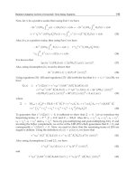
Fig. 5.32: Measured BER curves as a function of received optical power for the multiplexed
uplink signal, (S
U3
, C
U3
) after transmission over 10 km of SMF with the back-to-back (0.0 km
SMF) curve as a reference. The uplink signal was generated using an optical carrier separated by
500 GHz from the downlink carrier.
225
Chapter 5: Enabling Wavelength Interleaving in Millimetre-Wave Fibre-Radio
Networks
clearly demonstrate the functionality of the proposed DEMUX/MUX scheme in
multiplexing the uplink signals with optical carriers at wavelengths equal to the
difference between the downlink optical carriers and 5 × FSR.
5.7.4.2 Uplink by Reusing Downlink Optical Carrier
Fig. 5.33(a) shows the measured optical spectrum of the downlink signal after
recovering 50% of the carrier, while Figs. 5.33(b) – (c) present the optical spectra for
the recovered optical carrier and the generated uplink (S
U3
, C
U3
) before entering the
1555.9
1556.3
1556.7
Wavelength (nm)
Optical Power (dBm)
50%C
D3
-60
-40
-80
-20
0
S
D3
(a)
1555.9
1556.3
1556.7
Wavelength (nm)
Optical Power (dBm)
50%C
D3
-60
-40
-80
-20
0
(b)
1555.9
1556.3
1556.7
Wavelength (nm)
C
U3
-60
-40
-80
-20
S
U3
(c)
1555.9
1556.3
1556.7
Wavelength (nm)
Optical Power (dBm)
50%C
D3
-60
-40
-80
-20
0
S
D3
1555.9
1556.3
1556.7
Wavelength (nm)
Optical Power (dBm)
50%C
D3
-60
-40
-80
-20
0
S
D3
(a)
1555.9
1556.3
1556.7
Wavelength (nm)
Optical Power (dBm)
50%C
D3
-60
-40
-80
-20
0
1555.9
1556.3
1556.7
Wavelength (nm)
Optical Power (dBm)
50%C
D3
-60
-40
-80
-20
0
(b)
1555.9
1556.3
1556.7
Wavelength (nm)
C
U3
-60
-40
-80
-20
S
U3
1555.9
1556.3
1556.7
Wavelength (nm)
C
U3
-60
-40
-80
-20
S
U3
(c)
Fig. 5.33: Measured optical spectra of: (a): the downlink signal, (S
D3
, C
D3
) after recovering 50%
carrier, (b): the recovered optical carrier, and (c): the uplink signal, (S
U3
, C
U3
) generated using the
recovered carrier.
226
Chapter 5: Enabling Wavelength Interleaving in Millimetre-Wave Fibre-Radio
Networks
DEMUX/MUX scheme respectively. As expected, due to recovering 50% of optical
carrier, the CSR of the downlink signal is reduced by 3 dB, which eventually
contributes in improving the link performance, as illustrated in Section 5.4.2.
Spectra of Fig. 5.33(b)-(c) show that uplink DE-MZM experiences an unusual
insertion loss of 16 dB resulting in a weaker uplink signal. Such situation can be
avoided by placing a suitable DE-MZM having lower OSSB+C generation loss
(typical loss < 9 dB).
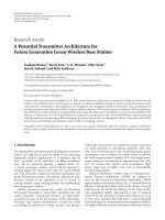
Fig. 3.34(a) presents the multiplexed uplink signal at the CO after transmission
over 10 km of SMF, while Fig. 5.34(b) presents the unwanted crosstalk at the CO
from the downlink path (in the absence of uplink signal in the link). The spectra
indicate that due to traversing through the AWG, the uplink signal is contaminated
by the unwanted in-band and out-of-band crosstalk by the reflections from the
downlink path, which is approximately -12 dB here. As before, the out-of-band
crosstalk from the downlink path does not require any special attention, and will
merge with typical crosstalk caused by the filtering characteristics of the
demultiplexer. However, the in-band crosstalk may need to be addressed and
managed when deploying such systems in practical networks. Fig. 5.34(a) also
1555.9
1556.3
1556.7
Wavelength (nm)
Optical Power (dBm)
C
U3
-60
-40
-70
-50
-30
S
U3
(a)
1555.9
1556.3
1556.7
Wavelength (nm)
-60
-40
-70
-50
-20
-30
C
D3
S
D3S
D2
S
D1
C
D1
C
D2
(b)
1555.9
1556.3
1556.7
Wavelength (nm)
Optical Power (dBm)
C
U3
-60
-40
-70
-50
-30
S
U3
1555.9
1556.3
1556.7
Wavelength (nm)
Optical Power (dBm)
C
U3
-60
-40
-70
-50
-30
S
U3
(a)
1555.9
1556.3
1556.7
Wavelength (nm)
-60
-40
-70
-50
-20
-30
C
D3
S
D3S
D2
S
D1
C
D1
C
D2
1555.9
1556.3
1556.7
Wavelength (nm)
-60
-40
-70
-50
-20
-30
C
D3
S
D3S
D2
S
D1
C
D1
C
D2
(b)
Fig. 5.34: Optical spectra measured at the CO for: (a): multiplexed uplink signal, (S
U3
, C
U3
) after
transmission over 10 KM SMF, and (b): unwanted crosstalk from the downlink path due to
reflections.
227
Chapter 5: Enabling Wavelength Interleaving in Millimetre-Wave Fibre-Radio
Networks
confirms the CSR of the multiplexed uplink (S
U3
, C
U3
) as 5 dB, although before the
proposed DEMUX/MUX scheme it was shown as 14 dB (shown in Fig. 5.33c). As
stated before, this reduction in CSR also improves the sensitivity of the link
significantly.
To quantify the signal degradation due to transmission over 10 km of SMF, uplink
(S
U3
, C
U3
) was detected and BER curves measured, both at the beginning (back-to-
back) and at the end of the fibre link using the same PD and data recovery circuit
described earlier. The recovered BER curves are presented in Fig. 5.35 and it can be
seen that the uplink (S
U3
, C
U3
) experiences a negligible 0.4 dB power penalty at a
BER of 10
-9
, which can be attributed to experimental errors. The presented
recovered optical spectra and the BER curves clearly demonstrate the functionality of
the proposed DEMUX/MUX scheme in multiplexing uplink signals that are
generated by employing a wavelength reuse technique which simplifies the BS by
-6
-7
-8
-9
-18.5 -18 -17.5 -17 -16.5 -16 -15.5
l
o
g
l
o
g
1
0
1
0
(
(
B
E
R
)
)
Received Optical Power (dBm)
with 10 KM SMF
with 0.0 KM SMF
Carrier Reused Uplink
-6
-7
-8
-9
-18.5 -18 -17.5 -17 -16.5 -16 -15.5
l
o
g
l
o
g
1
0
1
0
(
(
B
E
R
)
)
Received Optical Power (dBm)
with 10 KM SMF
with 0.0 KM SMF
Carrier Reused Uplink
Fig. 5.35: Measured BER curves as a function of received optical power for the multiplexed
uplink (S
U3
, C
U3
) after transported over 10 km SMF with the back-to-
b
ack (0.0 km SMF) curve as
reference, where uplink signal was generated by reusing the downlink optical carrier.
228
Chapter 5: Enabling Wavelength Interleaving in Millimetre-Wave Fibre-Radio
Networks
eliminating the light source from the uplink path while realising compact, low-cost
and light-weight BSs.
5.8 Effects of Optical Crosstalk on the Proposed System
Technologies
Section 5.4.1 has described the characteristics of the 8 × 8 AWG used in
demonstrating the system technologies throughout the Sections 5.4 to 5.7. The
characterised results indicate that the proposed schemes incorporating such AWG are
contaminated by the adjacent and nonadjacent channels crosstalk of -16 dB to -25 dB
and -29 dB to -46 dB respectively. The demultiplexed results in Sections 5.6.1 and
5.7.3 also confirm presence of crosstalk from -18 to -30 dB in the demultiplexed
signals. Moreover, the multiplexed results of the simultaneous MUX/DEMUX
scheme described in Section 5.7.4 demonstrate that uplink signals generated by using
37.5 GHz
155Mb/s BPSK
A1
A2
A3
A4
B5
B7
B8
A8
OSSB
3
+C
3
PD and Data
Recovery
BPF
OSSB
1
+C
1
OSSB
2
+C
2
S
3
, C
3
37.5 GHz
155Mb/s BPSK
A1
A2
A3
A4
B5
B7
B8
A8
OSSB
3
+C
3
PD and Data
Recovery
BPF
OSSB
1
+C
1
OSSB
2
+C
2
S
3
, C
3
Fig. 5.36: Experimental setup used to characterise optical crosstalk effects on the performance of
the optical mm-wave signals, using the proposed schemes incorporating AWG.
229
Chapter 5: Enabling Wavelength Interleaving in Millimetre-Wave Fibre-Radio
Networks
optical carriers spaced at 500 GHz from the downlink signals are contaminated by as
much as -17 dB optical crosstalk, which increases to -12 dB with the uplink signals
generated by reusing the downlink optical carriers. Therefore, there is the potential to
incur performance degradation of the proposed system technologies through optical
crosstalk. Fig. 5.36 shows the simplified experimental setup developed to
characterise the effects of optical crosstalk while transmitting the optical mm-wave
signals through the proposed system technologies incorporating AWG. Three
OSSB+C modulated optical mm-wave signals, each carrying 37.5 GHz-band 155
Mb/s BPSK data, were generated by using three optical carriers at the wavelengths
C
1
(1556.0 nm), C
2
(1556.2 nm) and C
3
(1556.4 nm). The modulated signals were
then applied to the AWG as shown in Fig. 5.36, where signals (S
1
, C
1
) and (S
2
, C
2
)
follow separate VOAs before being applied. The output at port B
5
was recovered in
such way that the signal (S
3
, C
3
) is contaminated by the adjacent and the nonadjacent
-30
-70
-60
-50
1556
1556.2
1556.4
Wavelength (nm)
Optical Power (dBm)
-40
1556.6
S
3
C
3
Adjacent
Crosstalk
Nonadjacent
Crosstalk
-30
-70
-60
-50
1556
1556.2
1556.4
Wavelength (nm)
Optical Power (dBm)
-40
1556.6
S
3
C
3
Adjacent
Crosstalk
Nonadjacent
Crosstalk
Fig. 5.37: Measured optical spectrum of the recovered signal (S
3
, C
3
) with adjacent and
nonadjacent channel crosstalk from neighboring signals (S
2
, C
2
) and (S
1
, C
1
) respectively.
230
Chapter 5: Enabling Wavelength Interleaving in Millimetre-Wave Fibre-Radio
Networks
channel crosstalk from the signals (S
2
, C
2
) and (S
1
, C
1
) respectively. The VOAs are
inserted to vary the optical powers of (S
1
, C
1
) and (S
2
, C
2
) that result in variable
optical crosstalk with the recovered signal (S
3
, C
3
). Also carrier C
3
was provisioned
two loop-backs before combining with S
3
, as the optical mm-wave signals are
expected to undergo two loop-backs while multiplexing (as described in Section 5.3).
The spectrum of the recovered signal (S
3
, C
3
) is shown in Fig. 5.37, where the
respective crosstalk components are mentioned in the insets. In order to observe the
effects of such crosstalk, the adjacent channel crosstalk is varied with a 3–dB interval
from -9 dB to -24 dB and the respective BER curves were measured as shown in Fig.
5.38. From the Fig. 5.38, it can also be seen that another two BER curves were
plotted with (i) adjacent channel crosstalk removed, but nonadjacent channel
crosstalk present, and (ii) both adjacent and nonadjacent channel crosstalk removed.
The BER curves indicate that the demonstrated schemes will endure noticeable
-6
-7
-8
-9
-19 -18.5 -18 -17.5 -17 -16.5 -16 -15.5
Adj. Xtalk: 9 dB
Adj. Xtalk: 12 dB
Adj. Xtalk: 15 dB
Adj. Xtalk: 18 dB
Adj. Xtalk: 21 dB
Adj. Xtalk: 24 dB
NO Adj. Xtalk
NO Xtalk
l
o
g
l
o
g
1
0
1
0
(
(
B
E
R
)
)
Received Optical Power (dBm)
-6
-7
-8
-9
-19 -18.5 -18 -17.5 -17 -16.5 -16 -15.5
Adj. Xtalk: 9 dB
Adj. Xtalk: 12 dB
Adj. Xtalk: 15 dB
Adj. Xtalk: 18 dB
Adj. Xtalk: 21 dB
Adj. Xtalk: 24 dB
NO Adj. Xtalk
NO Xtalk
l
o
g
l
o
g
1
0
1
0
(
(
B
E
R
)
)
Received Optical Power (dBm)
Fig. 5.38: Measured BER curves as a function of received optical power for various crosstalk
levels contaminating the recovered signal (S
3
, C
3
).
231
Chapter 5: Enabling Wavelength Interleaving in Millimetre-Wave Fibre-Radio
Networks
crosstalk induced penalties with the presence of crosstalk levels more than -21 dB,
which diminishes to zero when it is less than -21 dB.
In order to quantify the gradual changes in performance due to crosstalk, power
penalties incurred by the signal (S
3
, C
3
) (at a BER of 10
-9
) at various crosstalk levels
are compared and the results are plotted in Fig. 5.39. This graph shows that a power
penalty of 0.5 dB is observed for an optical crosstalk level of -16 dB, which however
increases to 1 dB when the crosstalk level increases to -12 dB.
0.4
0.8
1.2
1.6
-25 -20 -15 -10
Optical Crosstalk (dB)
Power Penalty (dB)
0
0.4
0.8
1.2
1.6
-25 -20 -15 -10
Optical Crosstalk (dB)
Power Penalty (dB)
0
Fig. 5.39: Measured crosstalk induced power penalties, with the gradual increase of crosstalk
levels in the transmitted signals by the demonstrated system technologies for WI-DWDM mm-
wave fibre-radio systems.
5.9 Conclusion
This chapter presented novel system technologies incorporating arrayed
waveguide grating filters for future wavelength-interleaved DWDM mm-wave fibre-
232
Chapter 5: Enabling Wavelength Interleaving in Millimetre-Wave Fibre-Radio
Networks
radio networks. WI-MUXs with the capacity to multiplex optical mm-wave signals
to the wavelength interleaving schemes for these networks are proposed, which also
improves the link performance by enabling reductions in CSRs of the multiplexed
signals. WI-DEMUX, capable of demultiplexing wavelength interleaved signals in
these networks, is also proposed. Moreover, a single MUX-DEMUX scheme for
simultaneous multiplexing and demultiplexing is proposed that offers a route towards
a simple network architecture by realising simplified and cost-effective CO and RNs.
The proposed schemes are based on standard AWG technology, therefore, are
suitable for integration with the other conventional technologies found in the optical
access or metro domain. These schemes incorporating a commercially available 8 × 8
AWG are demonstrated experimentally with three optical mm-wave signals spaced at
25 GHz, each of them carrying 37.5 GHz RF signal with 155 Mb/s BPSK data. The
error-free (at a BER of 10
-9
) recovery of data confirms the functionality of the
proposed schemes without significant power penalty observed while transported the
signals over 10 km of SMF. The AWG characteristics affecting the performance of
the demonstrated schemes have been investigated experimentally.
233
Chapter 5: Enabling Wavelength Interleaving in Millimetre-Wave Fibre-Radio
Networks
5.10 References
[1] H. Schmuck, R. Heidemann, and R. Hofstetter, “Distribution of 60 GHz signals to more than
1000 base stations,” Electron. Lett., vol. 30, pp. 59 – 60, Jan. 1994.
[2] R. Heidemann and G. Veith, “MM-wave photonics technologies for Gbit/s-wireless-local-
loop”, Proc. OECC’98, Chiba, Japan, pp. 310 – 311, 1998.
[3] J. O’Reilly and P. Lane, “Remote delivery of video services using mm-waves and optics,” J.
Lightwave Technol., vol. 12, no. 2, pp. 369-375, 1994.
[4] M. Shibutani, T. Kanai, W. Domom, W. Emura, and J. Namiki, “Optical fiber feeder for
microcellular mobile communication system (H-O15),” IEEE J. on Sel. Areas in
Communications, vol. 11, pp. 1118-1126, 1993.
[5] W. I. Way, “Optical fibre-based microcellular systems: an overview,” IEICE Trans.
Commun., vol. E 76-B, no. 9, pp. 1078-1090, 1993.
[6] O. K. Tonguz and J. Hanwook, “ Personal communications access networks using subcarrier
multiplxed optical links,” J. Lightwave Technol., vol. 14, pp. 1400-1409, 1996.
[7] P. Mahonen, T. Saarinen, Z. Shelby, and L. Munoz, “Wireless Internet over LMDS:
architecture and experimental implementation,” IEEE Communications Magazine, vol. 39,
pp. 126-132, 2001.
[8] S. Ohmori, Y. Yamao, and N. Nakajima,
“The future generations of mobile communications
based on broadband access technologies,”
IEEE Communications Magazine vol. 38, no. 12,
pp. 134-142, 2000.
[9] J. Zander, “Radio resource management in future wireless networks: requirement and
limitations,” IEEE Communications Magazine, vol. 35, no. 8, pp. 30-36, 1997.
[10] T. Ihara, and K. Fujumura, “Research and development trends of millimetre-wave short-
range application systems,” IEICE Trans. Commun., vol. E 79-B, no. 12, pp. 1741-1753,
1996.
[11] D. Wake, D. Johansson, and D. G. Moodie, “Passive pico-cell—New in wireless network
infrastructure,” Electron. Lett., vol. 33, pp. 404-406, 1997.
[12] G. H. Smith, D. Novak, and Z. Ahmed, "Technique for optical SSB generation to overcome
dispersion penalties in fiber-radio systems," Electron. Lett., vol. 33, pp. 74-75, 1997.
[13] G. H. Smith, D. Novak, and Z. Ahmed, “Overcoming chromatic dispersion effects in fiber-
wireless systems incorporating external modulators,” IEEE Trans. Microwave Theory Tech.,
vol. 45, no. 8, pp. 1410-1415, 1997.
234
Chapter 5: Enabling Wavelength Interleaving in Millimetre-Wave Fibre-Radio
Networks
[14] L.T. Nichols, and R. D. Esman, “Single sideband modulation techniques and applications,”
Proc. Conference on Optical Fiber Communication (OFC'99), San Diego, CA, USA, THW1-
1, 1999.
[15] K. Kitayama, “Highly spectrum efficient OFDM/PDM wireless networks by using optical
SSB modulation,” Journal of Lightwave Technol., vol. 16, no. 6, pp. 969-976, 1998.
[16] A. B. Sahin, O. H. Adamczyk, and A. E. Willner, “Dispersion division multiplexing
technique for doubling the spectral efficiency of subcarrier multiplexed data transmission
over fiber optical links,” Proc. Conference on Optical Fiber Communication (OFC'01),
Anaheim, CA, USA, paper WCC4, 2001.
[17] R. P. Braun, G. Grosskopf, D. Rohde, F. Schmidt, and G. Walf, “Fiber-optic millimeter-wave
generation at 64 GHz and spectral efficient data transmission for mobile communications,”
Proc. Conference on Optical Fiber Communication (OFC'98), Washington DC, USA, vol. 2,
pp. 17-18, 1998.
[18] A. Narasimha, X. J. Meng, M. C. Wu, and E. Yablonovitch, “Tandem single sideband
modulation scheme to double the spectral efficiency of analog fiber links,” Electron. Lett.,
vol. 36, no. 13, pp. 1135–1136, June 2000.
[19] A. Narasimha, X. Meng, C. F. Lam, M. C. Wu, and E. Yablonovitch, “Maximizing spectral
ation in WDM systems by microwave domain filtering of tandem single sidebands,”
IEEE
Trans. Micro. Theo. Tech., vol. 49, no. 10, pp. 2042-2027, 2001.
[20] G. H. Smith, D. Novak, and C. Lim, “A millimeter wave full-duplex fiber-radio star-tree
architecture incorporating WDM and SCM,” IEEE Photon. Technol. Lett., vol. 10, no. 11,
pp. 1650-1652, 1998.
[21] R. A. Griffin, P. M. Lane, and J. J. O’Reilly, “Radio-over-fiber distribution using an optical
millimeter-wave/DWDM overlay,” Proc. Conference on Optical Fiber Communication and
the International Conference on Integrated Optics and Optical Fiber Communications
(OFC/IOOC'99),San Diego, CA, USA, vol. 2, pp. 70-72, 1999.
[22] C. Lim, A. Nirmalathas, D. Novak, R. Waterhouse, and G. Yoffe, “A WDM architecture for
millimeter-wave fiber-radio systems incorporating baseband transmission,” IEEE Top. Meet.
On Microwave Photonics (MWP '99), vol.1, pp. 127-130, 1999.
[23] M. A. Al-mumin and G. Li, “WDM/SCM optical fiber backbone for 60 GHz wireless
systems,” Proc. IEEE. Top. Meet. on Microwave Photonics (MWP2001), Long Beach, CA,
USA, pp. 61-64, 2001.
[24] K. Kojucharow, M. Sauer, H. Kaluzni, D. Sommer, F. Poegel, W. Nowak, A. Finger, and D.
Ferling, “Simultaneous electrooptical upconversion, remote oscillator generation, and air
transmission of multiple optical WDM channels for a 60-GHz high-capacity indoor system,”
IEEE Transactions on Microwave Theory and Techniques, vol.47, pp. 2249-2256, 1999.
[25] C. Lim, A. Nirmalathas, D. Novak, R. S. Tucker, and R. Waterhouse, “Wavelength-
Interleaving Technique to Improve Optical Spectral efficiency In MM-wave WDM Fiber
235
Chapter 5: Enabling Wavelength Interleaving in Millimetre-Wave Fibre-Radio
Networks
radio” Lasers and Electro-Optics Society (LEOS ‘01), The 14th Annual Meeting of the IEEE,
San Diego, CA, USA vol. 1, pp. 54 –55, 2001.
[26] C. Lim, A. Nirmalathas, D. Novak, R. S. Tucker, and R. Waterhouse, “Technique for
increasing optical spectrum efficiency in millimeter wave WDM fiber-radio,” Electron. Lett.
, vol. 37, pp. 1043 –1045, 2001.
[27] H. Toda, T. Yamashita, K. Kitayama, T. Kuri, “A DWDM MM-Wave Fiber Radio system
by optical frequency interleaving for high spectra efficiency,” IEEE Top. Meet. On
Microwave Photonics (MWP '01), pp. 85-88, 2001.
[28] C. Lim, A. Nirmalathas, D. Novak, and R. Waterhouse, “Capacity analysis for a WDM fiber-
radio backbone incorporating wavelength-interleaving,” Optical Fiber Communication
Conference, vol. 1, pp. 355-357, 2002.
[29] C. Lim, A. Nirmalathas, D. Novak, and R. B. Waterhouse, “Network performance and
capacity analysis for a ring WDM fiber-radio backbone incorporating wavelength-
interleaving,” in Proc. OECC Yokohama, Japan, pp. 194-195, 2002.
[30] C. Lim, A. Nirmalathas, D. Novak, and R. B. Waterhouse, “Capacity analysis for WDM
fiber-radio backbones with star-tree and ring architecture incorporating wavelength
interleaving,” J. Lightwave Technol., vol. 21, no. 12, pp. 3308-3315, 2003.
[31] C. Lim, A. Nirmalathas, D. Novak, and R. Waterhouse, “Capacity analysis and optimum
channel allocations for a WDM ring fiber-radio backbone incorporating wavelength
interleaving with a sectorized antenna interface,” IEEE Top. Meet. On Microwave Photonics
(MWP '02), pp. 371-374, 2002.
[32] C. Marra, A. Nirmalathas, C. Lim, D. Novak, B. Ashton, L. Poladian, W. S. T. Rowe, T.
Wang, and J. A. Besley, “Wavelength-interleaved OADMs incorporating optimized multiple
phase-shifted FBGs for fiber-radio systems,” J. Lightwave Technol., vol. 21, no. 1, pp. 32-39,
2003.
[33] C. Marra et. al., “OADM with a multiple phase-shifted FBG for a wavelength-interleaved
millimeter-wave fiber-radio system,” Optical Fiber Communication Conference (OFC’02),
pp. 413-415, 2002.
[34] M. Bakaul, A. Nirmalathas, and C. Lim, “Dispersion Tolerant Novel Base Station Optical
Interface for Future WDM Fiber-Radio Systems,” Proc. of Conference on Optical Internet/
Australian Conference on Optical Fiber Technology (COIN/ACOFT’03), pp. 683-686, 2003.
[35] M. Bakaul, A. Nirmalathas, and C. Lim., “Multifunctional WDM optical interface for
millimeter-wave fiber-radio antenna base station”, J. Lightwave Technol., vol. 23, no. 3, pp.
1210 – 1218, 2005.
[36] A. Nirmalathas, C. Lim, M. Attygalle, D. Novak, R. Waterhouse, and M. Bakaul, "Recent
progress in fiber-wireless networks: Technologies and architectures" Proc. ICOCN2003,
Bangalore, India, Oct. 2003 (invited).
236
Chapter 5: Enabling Wavelength Interleaving in Millimetre-Wave Fibre-Radio
Networks
[37] M. Bakaul, A. Nirmalathas, and C. Lim, “Experimental verification of cascadability of WDM
optical interfaces for DWDM Millimeter-wave fiber-radio base station,” IEEE Top. Meet. On
Microwave Photonics (MWP '04), pp. 169 –172, 2004.
[38] M. Bakaul, A. Nirmalathas, and C. Lim., “Performance characterization of single as well as
cascaded WDM optical interfaces in millimeter-wave fiber-radio networks”, IEEE Photon.
Technol. Lett., vol. 18, no. 1, pp. 115-117, 2006.
[39] H. Toda, T. Yamashita, T. Kuri, and K. Kitayama, “25 GHz channel spacing DWDM
multiplexing using an arrayed waveguide grating for 60 GHz band radio on fiber systems,” in
Proc. International Topical meeting on Microwave Photonics (MWP’03), Budapest,
Hungary, pp. 287-290, 2003.
[40] M. Bakaul, A. Nirmalathas, C. Lim, D. Novak, and R. Waterhouse, “Simplified multiplexing
scheme for wavelength-interleaved DWDM millimeter-wave fiber-radio systems”, Proc.
European Conf. Optical Commun. (ECOC2005), Glasgow, Scotland, vol. 4, pp. 809 – 810,
2005.
[41] M. Bakaul, A. Nirmalathas, C. Lim, D. Novak, and R. Waterhouse, “Efficient multiplexing
scheme for wavelength-interleaved DWDM millimeter-wave fiber-radio systems”, IEEE
Photon. Technol. Lett., vol. 17, no. 12, pp. 2718-2720, 2005.
[42] T. Saito, T. Ota, T. Toratani, and Y. Ono, “16-ch Arrayed Waveguide Grating Module with
100-GHz Spacing,” Furukawa Review, no. 19, pp. 47-52 , 2000.
[43] K. A. McGreer, “Arrayed Waveguide Gratings for Wavelength Routing”, IEEE
Communications Magazine, December 1998.
[44] C. Dragone, “Efficient Techniques for widening the passband of a wavelength router”, J. of
Lightwave Technol., vol. 16, no. 10, pp. 1895 – 1906, 1998.
[45] P. Munoz, D. Pastor and J. Capmany, “Analysis and design of arrayed waveguide gratings
with MMI couplers”, Optics Express, vol. 9, no. 7, 2001.
[46] K.Okamoto and A. Sugita, “Flat Spectral response Arrayed Waveguide Grating multiplexer
with parabolic waveguide horns” Electron. Lett., vol. 32, pp. 1661-1662, 1996.
[47] S. Suzuki, “Arrayed Waveguide Gratings for dense-WDM systems”, in Proc. IEEE/LEOS
Summer Topical Meeting on WDM components Technology, Montreal, Canada, pp. 80 – 81,
Aug 11-15, 1997.
[48] T. Kamalakis and T. Sphicopoulos, “An Efficient Technique for the Design of an Arrayed-
Waveguide Grating with Flat Spectral Response”, J. Lightwave Technol., vol. 19, no. 11, pp.
1716-1725, 2001.
[49] M. C. Parker and S. D. Walker, “A Fourier-Fresnel Integral-Based Transfer Function Model
for a Near-Parabolic Phase Profile Arrayed Waveguide Grating”, IEEE Photon. Technol.
Lett., vol. 11, no. 8, pp. 1018-1020, 1999.
[50] M. K. Smit, C. V. Dam, “Phasar based WDM-devices: principles, design and applications”,
IEEE J. Selected Topics in Quantum Electron., vol. 2, no. 2, pp. 236-250, 1996.
237
Chapter 5: Enabling Wavelength Interleaving in Millimetre-Wave Fibre-Radio
Networks
[51] A. Klekamp and R. Munzer, “Imaging Errors in Arrayed Waveguide Gratings”, IEEE
Optical and Quantum Electron., vol. 35, pp. 333-345, 2003.
[52] P. Munoz, D. Pator, and J. Capmany “Modelling and Design of Arrayed Waveguide
Gratings”, J. Lightwave Technol., vol. 20, no. 4, pp. 661-674, 2002.
[53] J. Lam and L. Zhao “Design Trade-offs For Arrayed Grating DWDM MUX/DEMUX”, in
Proc. SPIE WDM and Photonic Switching Devices for Network Applications, vol. 3949, pp.
90-98, April 2000.
[54] H. Yamada, K. Takada and S. Mitachi, “Crosstalk Reduction in a 10 GHz Spacing Arrayed-
Waveguide Grating by Phase-Error Compensation,” J. of Lightwave Technol., vol. 16, no. 3,
pp. 364-371, 1998.
[55] C. Lim, M. Attygalle, A. Nirmalathas, D. Novak, and R. Waterhouse, “
Optimum modulation
depth for performance improvement in fiber-radio links,”
IEEE Top. Meet. On Microwave
Photonics (MWP '04), Maine, USA, pp. 89-92, 2004.
[56] C. Lim, A. Nirmalathas, D. Novak, and R. Waterhouse, “Capacity analysis and optimum
channel allocations for a WDM ring fiber-radio backbone incorporating wavelength
interleaving with a sectorized antenna interface,” IEEE Top. Meet. On Microwave Photonics
(MWP '02), pp. 371-374, 2002.
[57] A. Nirmalathas, C. Lim, M. Attygalle, D. Novak, R. Waterhouse, and M. Bakaul, "Recent
progress in fiber-wireless networks: Technologies and architectures" Proc. ICOCN2003,
Bangalore, India, Oct. 2003 (invited).
[58] H. Toda, T. Yamashita, K. Kitayama, T. Kuri, “Demultiplexing using an arrayed-waveguide
grating for frequency-interleaved DWDM radio-on-fiber systems with 25-GHz channel
spacing,” Proc. Int. Soc. Opt. Eng. (SPIE), vol. 4906, USA, pp. 99-106, 2002.
[59] H. Toda, T. Yamashita, K I. Kitayama, and T. Kuri, "A demultiplexing scheme using an
arrayed-waveguide grating for a DWDM mm-wave fiber-radio system by optical frequency
interleaving," Proc. 8th Microoptics Conference (MOC'01), C2, pp. 40-43, Osaka, Japan,
2001.
[60] H. Toda, T. Yamashita, T. Kuri, K. I. Kitayama,, “Demultiplexing using an arrayed-
waveguide grating for frequency-interleaved DWDM millimeter-wave radio-on-fiber
systems,” J. Lightwave Technol., vol. 21, pp. 1735-1741, 2003.
[61] A. Nirmalathas, C. Lim, D. Novak, R. Waterhouse, “Optical interfaces without light sources
for base station designs in fiber-wireless systems incorporating WDM,” IEEE Top. Meet. On
Microwave Photonics (MWP '99), vol.1 pp.119-122, 1999.
[62] A. Nirmalathas, D. Novak, C. Lim, R. Waterhouse, “Wavelength Reuse in the WDM Optical
Interface of a Millimeter-Wave Fiber-Wireless Antenna Base Station,” IEEE Trans.
Microwave Theory Tech., vol. 49, pp. 2006-2012, 2001.
[63] M. Bakaul, A. Nirmalathas, C. Lim, D. Novak, and R. Waterhouse, “Simplified multiplexing
and demultiplexing scheme for wavelength-interleaved DWDM millimeter-wave fiber-radio
238
Chapter 5: Enabling Wavelength Interleaving in Millimetre-Wave Fibre-Radio
Networks
systems”, in Proc. International Topical meeting on Microwave Photonics (MWP2005),
Seoul, South Korea, pp. 63-66, 2005.
[64] M. Bakaul, A. Nirmalathas, C. Lim, D. Novak, and R. Waterhouse, “Simultaneous
multiplexing and demultiplexing of wavelength-interleaved channels in DWDM millimeter-
wave fiber-radio networks, submitted to J. Lightwave Technol., 2005.
239
Chapter 5: Enabling Wavelength Interleaving in Millimetre-Wave Fibre-Radio
Networks
240
Chapter 6: Integration of Millimetre-Wave Fibre-Radio Networks in WDM
Optical Access Infrastructure
6
Integration of Millimetre-Wave
Fibre-Radio Networks in WDM
Optical Access Infrastructure
6.1 Introduction
The demand for higher and higher bandwidth necessitated by multimedia and real-
time applications is increasing universally across both fixed and mobile access
networks. To meet such growth in bandwidth demand, a variety of access
technologies are being introduced in the last mile access network, incorporating both
wireless and wireline media. Among these last mile access solutions, passive optical
network (PON) and its specific implementations such as fibre-to-the-home (FTTH),
and fibre-to-the curb (FTTC) remains as the most future proof technology for the
delivery of broadband to the users [1- 4]. Radio-over-fibre(RoF) network, which
broadly can be categorised as the networking of wireless access points are also very
attractive for the delivery of broadband via wireless last mile solutions [5 -7]. The
241
Chapter 6: Integration of Millimetre-Wave Fibre-Radio Networks in WDM
Optical Access Infrastructure
various access technologies, based on their spectral bands, can be re-grouped as
baseband (BB), intermediate frequency (IF), and mm-wave radio frequency (RF)
transport over fibre, as described in Chapter 2. Carriers and service providers are
actively seeking a convergent network architecture that can facilitate a rich mix of
value added and clearly differentiated services via a mix of wireless and wireline
solutions to meet the demand for mobility, bandwidth and range of connectivity
options from the customer [8 -10]. All these requirements can be met by offering an
integrated telecommunication package, for which an integrated access network is
essential. Given the wide bandwidth offered by fibre, an integrated optical access
network that can support appropriate integration of wired and wireless last mile
solutions seems very plausible and to enable such a network coexistence of the
optical access technologies in the same fibre will be essential.
Chapter 3, 4 and 5 have explored the system technologies for spectrally efficient
dense-wavelength-division-multiplexed (DWDM) RoF networks operating in mm-
wave frequencies, which reduce the cost of the deployment of such networks by
enabling a large number of base stations (BSs) through a single central office (CO)
[11-17]. The use of wavelength-division-multiplexed (WDM) in the RoF networks
allows a fast route for these systems to be developed by utilising the WDM optical
infrastructure in the access and metro network domains, where due to cost
effectiveness, the unused capacity will be used as the means of communication
between the CO and the BSs, by which the need for implementing separate fibre-
radio backbone can be avoided [18]. Therefore, it is important that RoF systems are
able to merge/integrate with the WDM access and metro network infrastructures.
In order to realise an integrated optical access network, simultaneous multiband
modulation techniques were previously proposed [10, 19-22], which enable BB, IF
and RF technologies to co-exist together in the same fibre. However, the
performance of these methods has been limited by the nonlinearity as well as the
optimum operating conditions of the modulators. Also, these techniques require
significant changes both in the existing mini switching centres (MSCs) and the
remote access nodes (RANs). Instead, if the passive system technologies (e.g.
multiplexer and demultiplexer) in the existing MSCs, equivalent to the COs and
RANs can be provisioned to support RF as well as other conventional BB and IF
242
Chapter 6: Integration of Millimetre-Wave Fibre-Radio Networks in WDM
Optical Access Infrastructure
access technologies thereby avoiding significant changes in the existing setup, an
effective integrated optical access network can be easily realised.
This Chapter thus focuses on the investigation of hybrid multiplexing and
demultiplexing schemes with the capacity to multiplex and demultiplex optically
modulated BB, IF and RF signals together, leading to an effective integrated optical
infrastructure in the access domain. Section 6.2 outlines general concept of
multiplexing multiband signals together with schemes depending on various WDM
channel separations. Section 6.3 presents a hybrid wavelength interleaving (WI)
technique and a hybrid multiplexer for the multiplexing of DWDM multiband
signals. The proposed wavelength-interleaved hybrid multiplexer is experimentally
demonstrated in Section 6.4. Section 6.5 investigates the demultiplexing techniques
suitable for demultiplexing multiple multiband signals from an integrated access
network and proposes several hybrid demultiplexers to support various WDM
channel separations. The proposed hybrid demultiplexer enabling demultiplexing of
wavelength-interleaved DWDM multiband signals are also experimentally
demonstrated in Section 6.6.
6.2 Multiplexing Multiband Signals in Integrated Access
Networks
Chapter 2 has described the characteristics of optically modulated BB, IF and RF
signals, the three broad categories of the signals generated by different optical access
technologies, which are expected to reside together in the desired integrated optical
access networks. In an integrated access network, three possible spectral schemes for
the multiband WDM signals may evolve: (i): WDM channel separation, ∆f is much
higher than the mm-wave RF frequency, f
RF
, (ii): WDM (DWDM) channel
separation, ∆f is equal to the mm-wave RF frequency, f
RF
, and (iii) DWDM channel
separation, ∆f is much smaller than the mm-wave RF frequency, f
RF
.
243
Chapter 6: Integration of Millimetre-Wave Fibre-Radio Networks in WDM
Optical Access Infrastructure
6.2.1 Multiplexing Scheme with WDM Channels Larger than
the RF Carrier Frequency
The schematic depicting the multiplexing scheme of multiband signals with
WDM channel spacing larger than the mm-wave RF carrier frequency is shown in
Fig. 6.1. It shows the spectra of N channels of each of the optically modulated BB, IF
and RF signals with a WDM channel separation and a mm-wave RF carrier
frequency of ∆f and f
RF
, respectively, where f
RF
<< ∆f. As f
RF
is much smaller than
∆f, the multiplexing of the signals in such spectral configuration can be realised by
using standard multiplexing technologies using a suitable arrayed waveguide grating
(AWG) multiplexer, where both the optical carrier and the modulation sideband of an
optically modulated RF signal will be considered together as a single channel, same
as the BB and IF signals.
BB
1
IF
1
S
1
C
1
S
N
C
N
BB
N
IF
N
λ
1
λ
2
λ
3
λ
3N-2
3N∆f
λ
3N
λ
3N-1
f
RF
∆f
∆f
∆f
∆f
RF
1
RF
N
BB
1
IF
1
S
1
C
1
S
N
C
N
BB
N
IF
N
λ
1
λ
2
λ
3
λ
3N-2
3N∆f
λ
3N
λ
3N-1
f
RF
∆f
∆f
∆f
∆f
BB
1
BB
1
IF
1
IF
1
S
1
C
1
S
N
C
N
BB
N
BB
N
IF
N
IF
N
λ
1
λ
2
λ
3
λ
3N-2
3N∆f
λ
3N
λ
3N-1
f
RF
∆f∆f
∆f∆f
∆f∆f
∆f∆f
RF
1
RF
N
Fig. 6.1: Schematic depicting the optical spectra of the multiplexed multiband signals in an
integrated access network with a WDM channel spacing larger than the mm-wave RF carrier
frequency.
Fig. 6.2 shows the schematic of the hybrid multiband multiplexer (H-MUX) that
realises multiplexing of the signals in the scheme shown in Fig. 6.1. It consists of a
3N × 1 AWG with a channel bandwidth, ≤∆f and a channel spacing, ∆f, equal to the
WDM channel spacing of the desired multiplexed multiband signals. The input ports
of the AWG are numbered from 1 to 3N.
The optically modulated BB, IF and RF
244
Chapter 6: Integration of Millimetre-Wave Fibre-Radio Networks in WDM
Optical Access Infrastructure
input signals enter the AWG via the input ports, 1 to 3N as per their respective
spectral positions shown in Fig. 6.1. The output of the AWG is, therefore, the
multiband signals multiplexed, the spectrum of which can be seen from the inset of
Fig. 6.2. This scheme has the potential to integrate 40 GHz and 60 GHz-band optical
RF signals to the WDM access and metro networks separated at 100 GHz.
OUTPUT
RF
1
,RF
2
, RF
N
,BB
1
,
BB
2
,…BB
N
,IF
1
,IF
2
,…IF
N
AWG Channel BW = ∆f
MM-Wave RF = f
RF
WDM Separation = ∆f
f
RF
<<<∆f
∆f
∆f
BB
N
IF
2
RF
N
BB
1
IF
1
RF
1
1
2
3
4
3N-2
3N-1
1
3N
3N × 1
AWG
4
5
INPUT
RF
1
IF
1
BB
1
RF
2
IF
2
BB
2
RF
N
IF
N
BB
N
OUTPUT
RF
1
,RF
2
, RF
N
,BB
1
,
BB
2
,…BB
N
,IF
1
,IF
2
,…IF
N
AWG Channel BW = ∆f
MM-Wave RF = f
RF
WDM Separation = ∆f
f
RF
<<<∆f
∆f
∆f
BB
N
IF
2
RF
N
BB
1
IF
1
RF
1
∆f
∆f
BB
N
IF
2
RF
N
BB
1
IF
1
RF
1
1
2
3
4
3N-2
3N-1
1
3N
3N × 1
AWG
4
5
INPUT
RF
1
IF
1
BB
1
RF
2
IF
2
BB
2
RF
N
IF
N
BB
N
Fig. 6.2: Proposed H-MUX enabling multiplexing of multiband signals in an integrated access
network with a WDM channel spacing larger than the mm-wave RF carrier frequency.
6.2.2 Multiplexing Scheme with DWDM Channels Equal to
the RF Carrier Frequency
The schematic depicting the multiplexing scheme of multiband signals with a
DWDM channel spacing equal to the mm-wave RF carrier frequency is shown in
Fig. 6.3. It shows the spectra of N channels of each of the optically modulated BB, IF
and RF signals with a DWDM channel separation, ∆f equal to the mm-wave RF
carrier frequency, f
RF
of the optical RF signal. Unlike the hybrid multiplexer shown
245
Chapter 6: Integration of Millimetre-Wave Fibre-Radio Networks in WDM
Optical Access Infrastructure
for the previous scheme, multiplexing of the optical RF signals with the BB and IF
signals in this case requires the optical carriers and the respective modulation
sidebands of the optical RF signals to be considered as separate channels.
S
1
C
1
BB
1
IF
1
∆f
∆f
∆f
∆f
∆f
∆f
λ
1
∆f
λ
2
λ
3
λ
4
λ
5
λ
6
λ
7
λ
8
S
2
C
2
BB
2
IF
2
4N∆f
∆f
∆f
∆f
S
N
C
N
BB
N
IF
N
λ
4N
λ
4N-1
λ
4N-2
λ
4N-3
∆f
∆f
4x∆f
S
1
C
1
BB
1
IF
1
∆f
∆f
∆f
∆f
∆f
∆f
λ
1
∆f
λ
2
λ
3
λ
4
λ
5
λ
6
λ
7
λ
8
S
2
C
2
BB
2
IF
2
4N∆f
∆f
∆f
∆f
S
N
C
N
BB
N
IF
N
λ
4N
λ
4N-1
λ
4N-2
λ
4N-3
∆f
∆f
4x∆f
Fig. 6.3: Schematic depicting the optical spectra of the multiplexed multiband signals in an
integrated access network with a DWDM channel spacing equal to the mm-wave RF carrier
frequency.
Fig. 6.4 shows the schematic of the H-MUX that realises multiplexing of the
signals in the spectral scheme shown in Fig. 6.3. It comprises a (4N+1) × (4N+1)
AWG with a channel bandwidth, ≤∆f and a channel spacing, ∆f, equal to the DWDM
channel spacing of the desired multiplexed multiband signals. . The input (A) and
output (B) ports of the AWG are numbered from 1 to 4N+1. The characteristic
matrix of the AWG that governs the allocation and distribution of different channels
at different ports is illustrated in Table. 6.1.
The optically modulated BB, IF and RF signals enter the AWG via the input ports,
A
2
to A
4N+1
as per their respective spectral positions shown in Fig. 6.3. The AWG
combines all the baseband signals BB
1
, BB
2
, ,BB
N
and IF signals IF
1
, IF
2
, ,IF
N
alongwith the modulation sidebands S
1
, S
2
,….,S
N
of RF signals at the output port B
1
.
Due to the cyclic characteristics of the AWG as illustrated in Table 6.1, the optical
carriers C
1
, C
2
,….,C
N
of the RF signals also exit as a composite signal via the output
246
Chapter 6: Integration of Millimetre-Wave Fibre-Radio Networks in WDM
Optical Access Infrastructure
port B
2
. The composite carriers C
1
, C
2
,….,C
N
are then looped back to the AWG
through the input port A
1
that redistributes the carriers to the odd-numbered output
ports B
3
, B
7
,….,B
4N-1
respectively. To realise the desired multiplexing, the
distributed carriers are again looped back to the AWG via the odd numbered input
ports A
3
, A
7
,….,A
4N-1
, respectively and the resultant output at port B
1
is the BB, IF
and RF signals multiplexed together. The multiplexed spectrum can be seen in the
insets of Fig. 6.4.
C
1
,C
2
,… C
N
A
1
A
2
A
3
A
4
A
4N-2
A
4N-1
B
1
B
2
B
3
B
4
A
4N
A
4N+1
B
4N-2
B
4N-1
B
4N
B
4N+1
C
N
C
2
C
1
A
5
A
6
A
7
A
8
B
5
B
6
B
7
B
8
A
9
B
9
<<
<
<<
<<
RF
N
(S
N
,C
N
)
IF
N
BB
N
RF
1
(S
1
,C
1
)
IF
1
BB
1
RF
2
(S
2
,C
2
)
IF
2
BB
2
OUTPUT
S
1
,S
2
, S
N
,C
1
,C
2
, C
N
,
BB
1
,BB
2
,…BB
N
,IF
1
,IF
2
,…IF
N
INPUT
AWG Channel BW = ∆f
MM-Wave RF = ∆f
DWDM Separation = ∆f
S
1
BB
1
C
1
IF
1
S
N
C
N
∆f
∆f
BB
N
IF
N
C
1
,C
2
,… C
N
A
1
A
2
A
3
A
4
A
4N-2
A
4N-1
B
1
B
2
B
3
B
4
A
4N
A
4N+1
B
4N-2
B
4N-1
B
4N
B
4N+1
C
N
C
2
C
1
A
5
A
6
A
7
A
8
B
5
B
6
B
7
B
8
A
9
B
9
<<
<
<<
<<
RF
N
(S
N
,C
N
)
IF
N
BB
N
RF
1
(S
1
,C
1
)
IF
1
BB
1
RF
2
(S
2
,C
2
)
IF
2
BB
2
OUTPUT
S
1
,S
2
, S
N
,C
1
,C
2
, C
N
,
BB
1
,BB
2
,…BB
N
,IF
1
,IF
2
,…IF
N
INPUT
AWG Channel BW = ∆f
MM-Wave RF = ∆f
DWDM Separation = ∆f
S
1
BB
1
C
1
IF
1
S
N
C
N
∆f
∆f
BB
N
IF
N
S
1
BB
1
C
1
IF
1
S
N
C
N
∆f
∆f
BB
N
IF
N
Fig. 6.4: Proposed hybrid multiplexer (H-MUX) enabling multiplexing of multiband DWDM
signals in an integrated access network with a DWDM channel spacing equal to the mm-wave RF
carrier frequency.
Due to the loop-backs (LBs), the optical carriers of the RF signals are suppressed
by as much as twice the insertion loss (2 × IL) of the AWG (typical IL = 4 - 5 dB)
compared to the respective modulation sidebands. Thus the proposed H-MUX
247
Chapter 6: Integration of Millimetre-Wave Fibre-Radio Networks in WDM
Optical Access Infrastructure
enhances the performance of the optically modulated RF signals enabling a reduction
in the carrier-to-sideband ratios (CSRs) by 8 to 10 dB [23 - 27], while multiplexing
them with the optically modulated baseband and IF signals, leading to an integrated
optical network in the access and metro domain. This scheme is particularly suitable
for integrating 25 GHz and 50 GHz-band optical RF signals in the DWDM access
and metro networks spaced at 25 GHz and 50 GHz respectively.
Output Ports
I / O
B
1
B
2
B
3
B
N-1
B
N
B
N+1
B
4N-1
B
4N
B
4N+1
A
1
λ
1
λ
2
λ
3
λ
N-1
λ
N
λ
N+1
λ
4N-1
λ
4N
λ
4N+1
A
2
λ
2
λ
3
λ
4
λ
N
λ
N+1
λ
N+2
λ
4N
λ
4N+1
λ
1
A
3
λ
3
λ
4
λ
5
λ
N+1
λ
N+2
λ
N+3
λ
4N+1
λ
1
λ
2
A
N-1
λ
N-1
λ
N
λ
N+1
λ
4N-4
λ
4N-3
λ
4N-2
λ
N-4
λ
N-3
λ
N-2
A
N
λ
N
λ
N+1
λ
N+2
λ
4N-3
λ
4N-2
λ
4N-1
λ
N-3
λ
N-2
λ
N-1
A
N+1
λ
N+1
λ
N+2
λ
N+3
λ
4N-2
λ
4N-1
λ
4N
λ
N-2
λ
N-1
λ
N
A
4N-1
λ
4N-1
λ
4N
λ
4N+1
λ
N-4
λ
N-3
λ
N-2
λ
4N-4
λ
4N-3
λ
4N-2
A
4N
λ
4N
λ
4N+1
λ
1
λ
N-3
λ
N-2
λ
N-1
λ
4N-3
λ
4N-2
λ
4N-1
Input Ports
A
4N+1
λ
4N+1
λ
1
λ
2
λ
N-2
λ
N-1
λ
N
λ
4N-2
λ
4N-1
λ
4N
Table 6.1: Input/output characteristic matrix of (4N+1) x (4N+1) AWG.
6.2.3 Multiplexing Scheme with DWDM Channels Smaller
than the RF Carrier Frequency
As stated before, the third possible scheme in multiplexing multiband signals in an
integrated access network is the use of a DWDM channel spacing smaller than the
mm-wave RF carrier frequency. The realisation of integrated networks with such
channel separation, however, is not practicable; as in such case, optically modulated
248
Chapter 6: Integration of Millimetre-Wave Fibre-Radio Networks in WDM
Optical Access Infrastructure
RF signals will overlap the neighbouring BB and IF signals. In order to resolve this
problem, the following section introduces a hybrid interleaving technique by which
multiplexing of multiband signals with a DWDM channel separation smaller than the
RF carrier frequency can be easily realised.
6.3 Hybrid Wavelength Interleaving
The data bandwidth capacity of a mm-wave RF signal is usually limited to several
hundred MHz; and therefore, the spectral band available between the optical carrier
and the respective modulation sideband of an optically modulated RF signal often
remains unused [13, 15, 16, 28, 29]. In order to realise a DWDM integrated access
network with a channel separation smaller than RF carrier frequency, the unused
spectral band of the optical RF signal can be utilised. If the unused spectral-bands of
the RF signals are sliced as per the desired DWDM channel separation, and the
neighbouring optically modulated BB and IF signals are interleaved at those sliced
RF
S1
RF
C1
BB
1
IF
1
∆f
∆f
∆f
∆f
∆f
∆f
λ
1
∆f
λ
2
λ
3
λ
4
λ
5
λ
6
λ
7
λ
8
RF
S2
RF
C2
BB
2
IF
2
4N∆f
∆f
∆f
∆f
RF
SN
RF
CN
BB
N
IF
N
λ
4N+1
λ
4N
λ
4N-1
λ
4N-2
3x∆f
4x∆f
RF
S1
RF
C1
BB
1
IF
1
∆f
∆f
∆f
∆f
∆f
∆f
λ
1
∆f
λ
2
λ
3
λ
4
λ
5
λ
6
λ
7
λ
8
RF
S2
RF
C2
BB
2
IF
2
4N∆f
∆f
∆f
∆f
RF
SN
RF
CN
BB
N
IF
N
λ
4N+1
λ
4N
λ
4N-1
λ
4N-2
3x∆f
4x∆f
Fig. 6.5: Schematic depicting the optical spectra of the wavelength interleaved multiband signals
in an integrated access network with a DWDM channel spacing smaller than the mm-wave RF
carrier frequency.
249