autocad 2007 and autocad lt 2007 bible - phần 5 pdf
Bạn đang xem bản rút gọn của tài liệu. Xem và tải ngay bản đầy đủ của tài liệu tại đây (1.96 MB, 130 trang )
478
Part II ✦ Drawing in Two Dimensions
Table 16-1 (continued)
Command Usable with Multilines Command Usable with Multilines
COPY yes ROTATE yes
EXPLODE yes SCALE yes
EXTEND yes STRETCH yes
FILLET no TRIM yes
You can use grips to stretch, move, copy, mirror, and rotate multilines.
To edit multilines, you use the MLEDIT command. To start MLEDIT, double-click the multiline
(or choose Modify ➪ Object ➪ Multiline) to open the Multilines Edit Tools dialog box, shown
in Figure 16-35.
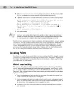
Figure 16-35: The Multilines Edit Tools
dialog box.
This dialog box enables you to edit multiline intersections and corners. You can also add or
delete a vertex. Click one of the images, and its name appears at the bottom of the dialog box.
The first column manages crossing intersections. To edit a crossing intersection, choose one
of the tiles in the first column and click OK. The command prompts you to pick a first multi-
line and then a second multiline. MLEDIT always cuts the first multiline that you pick. The
second one may be cut if it is called for by the edit type.
Although the command prompts you to pick two multilines, they can actually be two parts of
the same multiline.
The second column manages T-shaped intersections. To edit a crossing intersection, choose
one of the tiles in the second column and click OK. The command prompts you to pick a first
multiline and then a second multiline. MLEDIT always cuts the first multiline that you pick.
Note
23_788864 ch16.qxp 5/22/06 7:17 PM Page 478
479
Chapter 16 ✦ Drawing Complex Objects
The second one may be cut if it is called for by the edit type and depending on the shape of
the multiline.
The third column manages corners and vertices. The top tile creates a corner. The second tile
adds a vertex, and the third deletes a vertex. Choose the edit that you want and click OK. The
command prompts you to select a multiline. Be careful — you must pick the point where you
want to add or delete the vertex. To see the current vertices, pick the multiline with no com-
mand active to see the grips.
The last column of the dialog box makes cuts through multilines and welds them back
together again. Here’s how to use these options:
✦ Use the top tile to make a cut through one element of a multiline.
✦ Use the middle tile to cut through all of the elements of a multiline.
In both cases, you get a prompt to select a multiline and then a second point. Be
careful—the point that you use to select the multiline is the first point of the cut. For
a single cut, the pick point of the multiline also determines which element the com-
mand cuts.
✦ Use the bottom tile to remove the cuts. Removing cuts is called welding.
For all of these editing tools, you get prompts for further edits. Press Enter to end selection.
You can also move vertices using grips with the Stretch option.
An old command, TRACE, draws lines with width. Usually you can use polylines or multilines
instead to create the same effect.
Multiline styles are stored with the drawing, so that they can be updated and viewed, even if
the multiline style file containing the multiline definition is not available.
Creating Dlines in AutoCAD LT
Dlines are the AutoCAD LT equivalent of Multilines. AutoCAD does not include dlines. Dlines
(double lines) create line segments and arcs that are individual objects. The double lines and
arcs have nicely finished corners and ends. You can specify the width between the lines, off-
set the lines from your pick points, and cap the lines with a simple square cap.
To create a dline, choose Draw ➪ Double Line. The first prompt,
Specify start point or
[Break/Caps/Dragline/Snap/Width]:, gives you the following options:
✦ Break: Breaks the dline when it crosses other double lines, single lines, or arcs.
✦ Caps: Places a square cap at the start or end of the double line or at both the start and
end. Otherwise, use the None suboption.
✦ Dragline: Offsets the double line from your pick points. A positive value for this option
offsets to the right, and a negative value offsets to the left of your pick points. By default,
the double line is centered on either side of your pick points. You can also choose to use
the Left or Right suboptions to align the left or right line with your pick points.
✦ Snap: Ends a double line whenever you use an object snap.
✦ Width: Specifies the distance between the double lines.
Note
23_788864 ch16.qxp 5/22/06 7:17 PM Page 479
480
Part II ✦ Drawing in Two Dimensions
After you specify the first point, the prompt expands to give you three more options:
✦ Arc: Creates double arcs using this option. (You can’t easily do this in AutoCAD!) You
have suboptions that are similar to the ARC command options, including a Line option
to return to drawing lines segments.
✦ CLose: Draws a double line from the last point back to the first point.
✦ Undo: Undoes the last line segment or arc.
Because dlines are individual lines and arcs, there are no special editing tools and they are
easy to edit.
Using the SKETCH Command
The SKETCH command enables you to draw freehand. Freehand drawing is useful for contour
lines in architectural or civil engineering drawings, for illustrative effects, and for when you’re
feeling artistic. Although you may get best results if you have a digitizer and a stylus pen, you
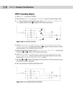
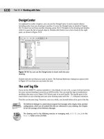
can sketch with a mouse or puck as well. Figure 16-36 shows some contour lines created with
SKETCH.
AutoCAD LT does not offer the Sketch feature.
Figure 16-36: Contour lines drawn with SKETCH.
Sketch can create lines or polylines. Polylines are probably easier to work with if you need to
edit the sketch later; you can use the PEDIT command. To specify whether SKETCH creates
lines or polylines, set the SKPOLY system variable. A value of zero creates lines, and a value
of one creates polylines.
Start the SKETCH command by typing sketch ↵. The command places you in a special sketch
mode and displays a special menu on the command line:
23_788864 ch16.qxp 5/22/06 7:17 PM Page 480
481
Chapter 16 ✦ Drawing Complex Objects
Record increment <0.1000>: Press Enter or type a new increment.
Sketch. Pen eXit Quit Record Erase Connect
Type the record increment, which is the length of the line or polyline segment that you want
to create. If the increment is too big, small movements do not create a segment at all, and the
sketch line appears jagged instead of smooth. However, you need to take into account the
scale of your drawing and your zoom factor. You should also turn off ORTHO and SNAP if
they’re on.
The pick button is equivalent to typing p, and toggles the pen up and down. Follow these
steps to start sketching:
1. Place the cursor where you want to start drawing.
2. Press the pick button. The prompt responds with the
<Pen down> message. You can
now draw.
3. Without holding down the pick button, move the mouse or stylus to create the shape
that you want. SKETCH creates a temporary green line.
4. After you finish, click the pick button again to see the
<Pen up> message.
5. Move the mouse to the starting point of your next line or polyline. Continue in this
manner until you finish sketching.
6. Type r to record the sketch. The prompt tells you what you created. The sketch
changes to the color of the current layer and becomes permanent, as shown in this
example:
4 polylines with 238 edges recorded.
7. Type x to exit Sketch mode.
Here are the other options:
✦ Quit: Quits Sketch mode without saving your sketch. The temporary line disappears.
✦ Erase: Erases temporary lines.
✦ Connect: Enables you to continue drawing from the end of the last sketch. Use this
when the pen is up. Type c and move to the endpoint of the last temporary sketch.
✦ . (Period): Enables you to draw straight line segments from the endpoint of the last
sketch. While the pen is up, type a period to add a line segment from the last endpoint
to your current cursor position.
The drawing used in the following exercise on sketching, ab16-h.dwg, is in the Drawings
folder on the CD-ROM.
STEPS: Sketching
1. Open ab16-h.dwg from your CD-ROM.
2. Save the file as
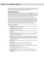
ab16-08.dwg in your AutoCAD Bible folder. It shows the front elevation
of a house. You’ll add the sketched path and contours, as shown in Figure 16-37.
3. Type skpoly ↵. Set SKPOLY to 1 and press Enter.
On the
CD-ROM
23_788864 ch16.qxp 5/22/06 7:17 PM Page 481
482
Part II ✦ Drawing in Two Dimensions
4. Type sketch ↵. At the Record increment <0'-0">: prompt, type 1 ↵ to set the record
increment to 1".
5. At the
Sketch. Pen eXit Quit Record Erase Connect. prompt, move the cursor to 1
in Figure 16-37. Click the pick button to put the pen down and draw the first line of the
path. Click the pick button to put the pen up.
6. Use the same technique to draw the other lines in Figure 16-37. If you make a mistake,
type q ↵ to quit and then start again.
7. After you’re done, type r to record the lines.
8. Type x to end the SKETCH command.
9. Save your drawing.
Figure 16-37: A sketched path and contours.
Digitizing Drawings with the TABLET Command
In Chapter 3, I explained that you can use a digitizer to execute commands. One important
use for a digitizer is to copy paper drawings into your drawing. Many companies have used
this technique to copy old drawings that were drafted by hand so that they could be edited
electronically. Digitizing can also be used to copy artwork and logos into a drawing.
To digitize a paper drawing, you use a special digitizing mode that turns the entire digitizer
into a drawing tablet. To start the TABLET command, choose Tools ➪ Tablet and choose one
of the options.
If you’ve been using the digitizer to execute commands, you need to reconfigure it to elimi-
nate the command areas and enlarge the drawing area. Use the Configure option of the
TABLET command and reconfigure the digitizer for 0 tablet menus. Respecify the screen
pointing area so that the fixed screen pointing area covers the entire digitizing area.
1
23_788864 ch16.qxp 5/22/06 7:17 PM Page 482
483
Chapter 16 ✦ Drawing Complex Objects
Attach the paper drawing securely to the digitizer so that it won’t move as you work.
To set up the digitizing mode, start the TABLET command and choose the Calibrate option.
The option prompts you to pick two points on the paper drawing and specify which coordi-
nates they represent. To do this you need to mark two points on the paper drawing; take out
a ruler and measure their distance. If the drawing has a title block, two corners of the title
block are distinctive points to mark and measure. If the drawing is drawn to a scale — and it
probably is—the coordinates you type should be the distance in real life, not the measure-
ment. In other words, if the two horizontal points are 1 inch apart and 1 inch represents 48
inches (a scale of 1=48), you could enter 0,0 for the first point and 48,0 for the second point.
However, it is usually useful to choose points over a wider area of your drawing. You can cali-
brate more than two points if you want.
If your drawing is distorted or uses a perspective view that you want to straighten out, you
can calibrate additional points and choose either Affine or Projective calibration to account
for the distortion. Affine calibration requires at least three points and scales the X and Y axes
separately. Projective calibration requires at least four points and stretches the coordinates to
adjust for the perspective view. You can provide up to 31 calibration points.
After you finish specifying calibration points and coordinates, press Enter. Now your entire
tablet can be used only for picking points. You can press F12 to use a menu or toolbar and
press F12 again to return to picking points, or type commands on the command line.
You can turn Tablet mode on and off by starting the TABLET command and choosing the On
and Off options. Tablet calibration settings are lost when you close the drawing session.
Choose the command that you need and pick points along the paper drawing. After you’re
done, turn off Tablet mode and do any necessary editing and cleanup.
In this exercise, you practice digitizing drawings. If you have a digitizer, you can try this exer-
cise. Otherwise, skip it.
STEPS: Digitizing Drawings
1. Start a new drawing using acad.dwt or acadlt.dwt as your template.
2. Save the file as
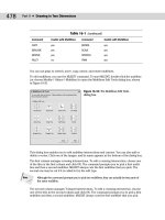
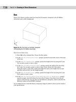
ab16-09.dwg in your AutoCAD Bible folder. This is a sheet metal tem-
plate as shown in Figure 16-38.
3. Make a photocopy of Figure 16-38 and tape it to the active area of your digitizer.
4. Choose Tools➪ Tablet ➪ Calibrate. Follow the prompts:
Digitize point #1: Pick 1 in Figure 16-38.
Enter coordinates for point #1: 0,0 ↵
Digitize point #2: Pick 2 in Figure 16-38.
Enter coordinates for point #2: 7,5 ↵
Digitize point #3 (or RETURN to end): ↵
5. Type tablet ↵ and on ↵.
6. Type line ↵.
Note
Note
23_788864 ch16.qxp 5/22/06 7:17 PM Page 483
484
Part II ✦ Drawing in Two Dimensions
7. In Figure16-38, pick 3 with the digitizer, then 4, and then each line endpoint in
turn, counterclockwise around the figure.
8. After you reach
5, do not digitize point 1 again. Instead, type c ↵ to close the
figure exactly.
9. Type tablet ↵. Type off ↵ to return the digitizer to Screen Pointing mode.
10. Save your drawing.
Figure 16-38: An unfolded sheet-metal
template.
Summary
Several types of complex objects add greatly to the capabilities of AutoCAD and
AutoCAD LT. In this chapter, you read about:
✦ Using polylines to combine lines, segments, and arcs of any width into one
object
✦ Utilizing splines to mathematically calculate curves, fit to points that you
specify
✦ Using regions, which are two-dimensional surfaces
✦ Creating regions or polylines from complex areas by using the BOUNDARY
command
✦ Filling in an area with lines, a solid fill, or a gradient with hatches
2
3
4
5
1
23_788864 ch16.qxp 5/22/06 7:17 PM Page 484
485
Chapter 16 ✦ Drawing Complex Objects
✦ Drawing complex parallel lines at one time with multilines (AutoCAD only), and draw-
ing double lines with AutoCAD LT
✦ Drawing freehand by using the SKETCH command, creating either lines or polylines
(AutoCAD only)
✦ Using a digitizer in Tablet mode, when you need to copy a paper drawing into AutoCAD
In the next chapter, I explain how to lay out and plot a drawing.
✦✦✦
23_788864 ch16.qxp 5/22/06 7:17 PM Page 485
23_788864 ch16.qxp 5/22/06 7:17 PM Page 486
17
17
CHAPTER
Plotting and
Printing Your
Drawing
M
ost drawing jobs are not complete until you see the final result
on paper. Traditionally, drawings are plotted on a plotter.
However, you can also print a drawing on a regular computer printer.
Many printers and plotters can handle a wide range of drawing sizes
and paper types. In this chapter, I explain the process of preparing a
drawing for plotting, including laying it out in paper space, more
properly known as a layout. Finally, I cover the actual process of
creating a plot.
Preparing a Drawing for
Plotting or Printing
When you complete your drawing, you often have some details to fin-
ish. If you didn’t start with a title block, you may need to insert one.
Even if you have a title block, you may need to complete some of its
annotation, such as the date that you completed the drawing. If the
drawing has layers that you don’t want to appear on paper, you
should set their layer state to Frozen, Off, or Not Plottable.
Many architectural and mechanical drawings show several views of
the model. Now is the time to check that the views are pleasingly laid
out, with enough space between them for dimensions and annotation.
Doing a draft plot
You may want to do a draft plot, either to check the drawing itself or
to be sure that it will print out properly. Although you can preview
the plot, sometimes the results are not what you want, and it pays to
test the plot on inexpensive paper before plotting on expensive vel-
lum. Draft plots for checking purposes can often be done on a printer.
Some companies have wide-format inkjet printers that accept 17×22-
inch paper and are used exclusively for check plots. Even if the final
plot will be all in black, a color printer is a good choice for draft plots
because you can easily check the layer scheme.
✦✦✦✦
In This Chapter
Preparing a drawing for
plotting or printing
Creating a layout in
paper space
Working with plot styles
Plotting a drawing
✦✦✦✦
24_788864 ch17.qxp 5/22/06 7:20 PM Page 487
488
Part II ✦ Drawing in Two Dimensions
Plotting a drawing from model space
Model space refers to the mode in which you work when you draw and edit your model.
Throughout this book, the discussions and exercises have assumed that you were in model
space. By default, AutoCAD and AutoCAD LT have two buttons on the status bar that let you
switch between model space and a layout. When the Model button is indented, you know that
you’re in model space, as shown in Figure 17-1.
You can switch between two methods for displaying model and paper space (layouts). The
default shows two buttons on the status bar — a model button and a button for the current
layout. You can click the arrows to access a menu listing additional layouts. See Figure 17-1.
This system increases the drawing area slightly.
Figure 17-1: You can switch between model
and paper space using the buttons on the
status bar.
Previous releases used tabs for model space and each of the layouts, as shown in Figure 17-2.
To display the tabs instead of the buttons on the status bar, right-click either button and
choose Display Layout and Model Tabs.
After you’ve prepared your drawing for plotting, as just discussed, you can plot your drawing.
See the discussion on plotting later in this chapter.
You can also plot entire sheet sets. For more information, see Chapter 26. The PUBLISH com-
mand, which I cover in Chapter 28, lets you plot multiple drawings.
Creating a Layout in Paper Space
If you’re using several views of your model, you should consider creating a paper space lay-
out. Although paper space was designed for the needs of 3D drawings, it’s often used for 2D
layout as well. For example, if you want to show views of your model at different scales, paper
space is indispensable. If you use a title block, paper space is a good choice, because the size
of the title block needs to be appropriate for the sheet of paper on which you will plot. Paper
space is a tool for laying out a drawing. It’s analogous to creating a sheet of paper at the size
on which you’ll plot, and placing views on the paper. You place the views by means of floating
viewports. Floating viewports on a paper space layout are windows into model space, through
which you see your drawing.
A layout provides a visual environment that lets you know what your plot will look like. By cre-
ating more than one layout for a drawing, you can create more than one plot for a single draw-
ing. For example, you can create layouts at different scales for different sheet sizes or layouts
with different layer states for contractors who need to see varying aspects of a drawing.
Cross-
Reference
Click to display the model and layout tabs
Model button
Current layout button
Additional Layouts menu
New
Feature
24_788864 ch17.qxp 5/22/06 7:20 PM Page 488
489
Chapter 17 ✦ Plotting and Printing Your Drawing
Entering paper space
You draw in model space, which you access by clicking the Model button on the status bar or
the Model tab at the bottom of the screen. You use a paper space layout to lay out a drawing.
When you’re in paper space, you can view your drawing only through floating viewports.
To enter a paper space layout, simply click the layout button on the status bar. If you are
using tabs, click a layout tab. By default, you see one floating viewport through which you
can view your model. An example is shown in Figure 17-2. The paper space icon and the lay-
out tab confirm that you’re looking at a paper space layout.
Figure 17-2: When you display a layout, the layout is automatically
created, with one floating viewport through which you can see your
entire drawing.
To switch back to model space, click the Model button or tab.
Using the Layout Wizard
The Layout Wizard guides you through the process of laying out a drawing in paper space.
Although you may eventually want to lay out your drawings on your own, the Layout Wizard
is a great way to get started using a paper space layout.
To use the Layout Wizard, follow these steps:
1. Choose Tools➪ Wizards➪ Create Layout. You see the wizard screen shown in Figure
17-3, where you name the layout. This name will appear on the Additional Layouts
menu on the status bar or on the layout tab at the bottom of the drawing area.
Printable area of paper
Floating viewport
Paper space icon
Model tab
Current layout tab
Paper size of current plotter or printer
24_788864 ch17.qxp 5/22/06 7:20 PM Page 489
490
Part II ✦ Drawing in Two Dimensions
Figure 17-3: The first screen of the Layout Wizard.
2. Type a name for the layout and click Next.
3. The second screen asks you to choose a configured plotter. This list also includes print-
ers. For more information on configuring a plotter or printer, see Appendix A. Click
Next after you’re done.
4. On the third screen, shown in Figure 17-4, specify a paper size and drawing units, and
then click Next.
Figure 17-4: The Paper Size screen of the Layout Wizard.
5. On the next screen, specify whether you want the drawing to plot in portrait or land-
scape orientation. The wizard rotates a letter A on a sheet of paper so that you can see
which way your drawing will plot. Then click Next.
6. On the Title Block screen, shown in Figure 17-5, choose a title block if you want to add
one. You can add it as a block (see Chapter 18) or as an external reference, or xref (see
Chapter 19).
24_788864 ch17.qxp 5/22/06 7:20 PM Page 490
491
Chapter 17 ✦ Plotting and Printing Your Drawing
To add your own title block, create it as a drawing and save it in the \Templates folder or
create your own folder for your templates. (To find the location of the \Templates folder,
choose Tools➪ Options and click the Files tab. Double-click Template Settings and then
Drawing Template File Location. To use your own folder, change this location. Using your
own folder reduces the chance that you’ll lose your templates when you reinstall or
upgrade.) Notice that most of the templates in that folder have corresponding drawings that
are used in the Layout Wizard. If you have a template that you use for a title block, open a
new drawing using that template and save it as a drawing in the \Templates folder, using
the same name as the template. (It now has a .dwg file name extension.)
Figure 17-5: The Title Block screen of the Layout Wizard.
7. On the Define Viewports screen, shown in Figure 17-6, you choose from four viewport
configuration options:
• Choose None if you want to create your own floating viewports.
• Choose Single to create one viewport.
• Choose Std. 3D Engineering Views to create a 2×2 array of top, front, side, and
isometric views.
• Choose Array to specify how many views you want, in rows and columns.
You can also set the viewport scale. Then click Next.
For more information on scales, see Chapter 5. Also see the discussion of viewport scales
later in this chapter.
8. On the Pick Location screen, the wizard prompts you to pick two corners to define the
size of the viewport configuration that you chose. If you chose more than one viewport,
these two corners define the extents of all of the viewports combined, not the extents
of the individual viewports. Click Next.
9. On the last screen, click Finish to close the wizard and return to your drawing.
Cross-
Reference
Tip
24_788864 ch17.qxp 5/22/06 7:20 PM Page 491
492
Part II ✦ Drawing in Two Dimensions
Figure 17-6: The Define Viewports screen of the Layout Wizard.
Figure 17-7 shows the result of completing the wizard with a 2×1 array of viewports. Usually,
you still need to pan the model and change the scale to get the view that you want in each
viewport.
Figure 17-7: After completing the Layout Wizard, you now see your
model in the viewport(s) that you created.
In the following exercise, you practice using the Layout Wizard to create a paper space layout.
The drawing used in the following exercise on creating a paper space layout with the Layout
Wizard, ab17-a.dwg, is in the Drawings folder on the CD-ROM.
On the
CD-ROM
24_788864 ch17.qxp 5/22/06 7:20 PM Page 492
493
Chapter 17 ✦ Plotting and Printing Your Drawing
STEPS: Creating a Paper Space Layout with the Layout Wizard
1. Open ab17-a.dwg from your CD-ROM.
2. Save the file as
ab17-01.dwg in your AutoCAD Bible folder.
3. Choose Tools➪ Wizards➪ Create Layout.
4. On the Begin screen, type Double as the name of the layout. Click Next.
5. On the Printer screen, choose the printer or plotter that you want to use. Click Next.
6. On the Paper Size screen, choose a paper size that you have available and that is suit-
able for the printer or plotter that you chose on the previous screen. The drawing units
should be in inches, but you can use millimeters, if you prefer. Click Next.
7. On the Orientation screen, choose Landscape. (This is the default.) Click Next.
8. On the Title Block screen, choose
ANSI A title block.dwg. The type should be set to
Block. Click Next.
9. On the Define Viewports screen, choose Array. Set Rows to 1 and Columns to 2. Choose
1:4 from the Viewport Scale drop-down list. Click Next.
10. On the Pick Location screen, click Select Location. In the drawing, choose a point near
the top of the border on the left, and a second point at the bottom-right of the border,
just above the title block. If necessary, turn off OSNAP.
11. Click Finish.
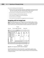
12. Save your drawing. It should look like Figure 17-8.
Figure 17-8: Using the Layout Wizard to create a paper space layout with floating
viewports.
24_788864 ch17.qxp 5/22/06 7:20 PM Page 493
494
Part II ✦ Drawing in Two Dimensions
Laying out a drawing in paper space on your own
Now that you’ve used the Layout Wizard once, you can try creating layouts on your own. The
Layout Wizard only creates the floating viewports, leaving the scaling, panning, and other
tasks up to you.
Managing layouts
You can have up to 256 layouts, including model space. To create a new layout, first display
the tabs. (If they’re not displayed, right-click the current layout button on the status bar and
choose Display Layout and Model Tabs.) Right-click an existing layout tab and choose from
the following options on the shortcut menu:
✦ New layout: Creates a new layout.
✦ From template: Opens the Select File dialog box in which you can choose a
.dwg, .dxf,
or
.dwt file. Click Open. You can then choose the layout or layouts that you want from
the Insert Layout(s) dialog box. When you import a template, you import everything
that exists on the paper space layout, including viewports, any existing text, the title
block, and so on. (You can then get rid of anything you don’t want, if necessary.)
If you import a layout from a drawing, any layers, linetypes, and such also come along for the
ride. Use the PURGE command to get rid of anything that you don’t need. See Chapter 11 for
information on purging. You can also import a layout using the DesignCenter. See Chapter
26 for details.
✦ Delete: Deletes the selected layout. A warning dialog box appears. Click OK to delete
the layout.
✦ Rename: Opens the Rename Layout dialog box, where you can rename the layout.
Click OK.
✦ Move or Copy: Opens the Move or Copy dialog box. To move a layout tab, you choose
the layout tab that you want the selected tab to be to the left of. You can also choose to
move it to the end. Click Create a copy to copy the selected tab. (You can then rename
it.) Click OK after you’re done.
✦ Select All Layouts: Selects all layouts. You can then delete them.
✦ Activate Previous Layout/Activate Model Tab: Moves you to the last layout tab that
you had displayed or to the Model tab.
✦ Page Setup Manager: Opens the Page Setup Manager, which is discussed next.
✦ Plot: Opens the Plot dialog box, which is discussed later in this chapter.
✦ Publish Selected Layouts: If two or more layouts are selected, you can use this item to
start the PUBLISH command with the selected layouts in the list of sheets to publish.
For more information on the PUBLISH command, see Chapter 28.
✦ Hide Layout and Model Tabs: Hides the tabs.
To move through the tabs (Model and all of the layout tabs) from left to right, press
Ctrl+Page Down. To move from right to left, press Ctrl+Page Up.
Tip
Cross-
Reference
24_788864 ch17.qxp 5/22/06 7:20 PM Page 494
495
Chapter 17 ✦ Plotting and Printing Your Drawing
Using the Page Setup Manager
When you click a new (unused) layout tab, or choose it from the layout button (or Additional
Layouts menu) on the status bar, by default you see one floating viewport. However, you can
create and save page setups that store many of the settings that were explained previously in
the discussion of the Layout Wizard. The value in saving page setups is that the settings are
attached to the layout. If you have more than one layout, each with its own page setup, then
you can quickly switch the page settings as you move from layout to layout. Once you have
page setups, you can manage them in the Page Setup Manager, shown in Figure 17-9.
Figure 17-9: The Page Setup Manager helps you
to control your page setups.
When you check the Display When Creating a New Layout check box, the Page Setup Manager
automatically appears each time you display a layout for the first time. To display it if it does
not appear, right-click the current paper space layout tab (you need a tab to do this) and
choose Page Setup Manager; then check the check box. You can also specify whether you
want the Page Setup Manager to appear when you click a new layout by choosing Tools ➪
Options and clicking the Display tab. Check or uncheck the Show Page Setup Manager for
New Layouts check box.
To display the Page Setup Manager, right-click any layout tab and choose Page Setup
Manager. The Page Setup Manager lists your layouts and page setups. You can create a new
page setup, modify an existing setup, or set a page setup current for the active layout. Click
the Import button to import a page setup from another drawing.
To create a new page setup, click New. In the New Page Setup dialog box, enter a name for the
page setup. Choose an existing page setup to start from so that you don’t have to change all
of the settings, and click OK. The Page Setup dialog box appears, as shown in Figure 17-10.
Note
24_788864 ch17.qxp 5/22/06 7:20 PM Page 495
496
Part II ✦ Drawing in Two Dimensions
Figure 17-10: The Page Setup dialog box.
Here’s how to use the Page Setup dialog box:
✦ Printer/Plotter: Choose a printer or plotter from the drop-down list. For more informa-
tion, see “Specifying plot settings” later in this chapter.
✦ Paper size: Choose a paper size from the drop-down list.
✦ Plot area: By default, the plot is set to the layout. However, you can choose to plot the
current display, the drawing extents, a named view, or a window that you specify.
✦ Plot offset: You can move the plot from the lower-left corner. Specify the X and Y offset
in inches. If you aren’t plotting the layout, but rather some smaller area, check the
Center the Plot check box to center the plot on the paper.
✦ Plot scale: Set the scale from the drop-down list. You can also type a scale in the text
boxes. Because you scale your model in your floating viewports, you usually don’t have
to scale the layout as well. Therefore, you typically plot a layout in paper space at 1:1. If
you’re using lineweights and want to scale them, check the Scale Lineweights check box.
✦ Plot style table: Choose a plot style table if you want to use one. For more information,
see the section “Working with Plot Styles” later in this chapter.
✦ Shaded viewport options: Use this feature to determine the display of the Model tab.
(To set the display of a viewport on a layout, select the viewport and make the changes
in the Properties palette.) With the Model tab displayed, choose one of the Shade Plot
display options: As Displayed, Wireframe, Hidden, 3D Hidden, 3D Wireframe,
Conceptual, Realistic, Rendered, Draft, Low, Medium, High, or Presentation. You can
also choose a quality (resolution)—Draft, Preview, Normal, Presentation, Maximum, or
Custom. If you choose the Custom quality, you can specify the dots per inch (dpi).
(AutoCAD only.)
✦ Plot options: Clear the Plot Object Lineweights check box if you used lineweights but
don’t want the lineweights to be plotted. Clear the Plot with Plot Styles check box if
you assigned plot styles to layers or objects but don’t want to plot them. (Plot styles
are discussed later in this chapter.) Clear the Plot Paperspace Last check box in order
to plot objects drawn on the paper space layout first. Check the Hide Paperspace
24_788864 ch17.qxp 5/22/06 7:20 PM Page 496
497
Chapter 17 ✦ Plotting and Printing Your Drawing
Objects check box to hide lines of 3D objects that you created in paper space. (Later in
this chapter, I explain how to hide lines of 3D objects that were created in model space,
a more common situation.)
✦ Drawing orientation: Choose portrait or landscape. You can also choose to plot
upside-down. Use these settings to rotate a drawing when you plot it.
When you’ve completed your settings in the dialog box, click OK to return to the Page Setup
Manager. You can see the new page setup in the list. To make the page setup active, click Set
Current. Then click Close to return to your drawing.
You can import settings saved in PCP or PC2 files from earlier releases of AutoCAD or
AutoCAD LT. PCP and PC2 files contain plot settings that are similar to those that you set in
the Page Setup dialog box. Click the layout you want to use and choose Tools ➪ Wizards ➪
Import Plot Settings. In the Import PCP or PC2 Settings Wizard, follow the instructions to
import the PCP or PC2 file.
Preparing layers
If necessary, create the layers that you need. If you want to insert a title block, create a sepa-
rate layer for it. The actual viewports should also be on their own layer, because it’s common
to freeze that layer or set it to non-plottable, so that the borders don’t show. Even if you want
to plot the viewports, making them a different color from your model helps you to easily dis-
tinguish them.
Inserting a title block
Insert the title block. You can have a file that contains just the title block. You can also use a
block or external reference. Putting the title block on your layout is common because it
defines the edges of your paper and is not a real-life object. These qualities make it appropri-
ate for paper space, which also relates to your paper, rather than the real-life model that
you’ve drawn.
Creating floating viewports
Remember that you need a floating viewport to see your model on a paper space layout. The
default is one floating viewport. Floating viewports have properties that are important to
understand when you’re creating layouts in paper space. These properties are:
✦ Unlike tiled viewports (see Chapter 8), floating viewports are actual objects that you
can erase, move, and stretch. They can—and should—be on separate layers, so that
you can control the visibility of the viewport borders when desired. They don’t need to
take up the entire screen. You can define their size and location freely.
✦ In paper space, the crosshairs are not limited to one floating viewport.
✦ You can separately set the visibility of the UCS icon in each floating viewport.
✦ You can create as many viewports as you want, but it’s best to keep the drawing
uncluttered.
✦ Whatever you draw in paper space does not affect your models; it exists only in paper
space and disappears when you click the Model tab or button.
✦ After you create floating viewports, you can switch to model space and work on your
models while still on the layout. To do so, double-click inside a viewport. You do this
mostly to adjust the view of the model in the viewport. In model space, floating view-
ports are similar to tiled viewports in that only one can be active at a time.
Note
24_788864 ch17.qxp 5/22/06 7:20 PM Page 497
498
Part II ✦ Drawing in Two Dimensions
Because viewports are created on the current layer, you need to make the desired layer cur-
rent. Then, to create floating viewports, choose View ➪ Viewports while on a layout. Choose
from the following submenu items:
✦ Named Viewports: If you’ve saved a tiled viewport configuration, choose this option to
open the Viewports dialog box. On the Named Viewports tab, choose the configuration
from the list and click OK. In other words, you can use a tiled viewport configuration
for floating viewports. See Chapter 8 for a full discussion of saving viewport configura-
tions.
✦ New Viewports: Choose this item to open the Viewports dialog box, shown in Figure
17-11. Choose one of the standard configurations, which you can see in the Preview
box. Click OK to create the viewports.
If you have saved named views, you can immediately display them in a viewport. Click one
of the viewports in the Preview pane and choose the named view from the Change View To
drop-down list. At the same time, you can specify a visual style for each viewport. (I cover
visual styles in Chapter 22; visual styles are available in AutoCAD only.) You can do this for
each viewport that you create.
Figure 17-11: Use the Viewports dialog box to choose one of
the standard configurations of floating viewports.
✦ 1 Viewport: You see the Specify corner of viewport or [ON/OFF/Fit/Shadeplot/
Lock/Object/Polygonal/Restore/2/3/4] <Fit>: prompt on the command line. You
can pick two diagonally opposite points or use the Fit option to create one viewport
that fits the entire screen.
AutoCAD LT does not include the Object or Polygonal options. You cannot create non-rect-
angular viewports in AutoCAD LT.
Tip
24_788864 ch17.qxp 5/22/06 7:20 PM Page 498
499
Chapter 17 ✦ Plotting and Printing Your Drawing
✦ 2 Viewports: Creates two floating viewports. You can choose a horizontal or vertical
configuration. You can choose Fit to fit them to the entire screen or pick diagonal
points. The diagonal points define the combined two viewports, not each viewport.
✦ 3 Viewports: Creates three floating viewports. You can choose from several configura-
tions. You can choose Fit to fit them to the entire screen or pick diagonal points. The
diagonal points define the combined three viewports, not each viewport.
✦ 4 Viewports: Creates four floating viewports. You can choose Fit to fit them to the
entire screen or pick diagonal points. The diagonal points define the combined four
viewports, not each viewport.
✦ Polygonal Viewport: Lets you create a viewport using a combination of line segments
and arcs, with prompts similar to those that you see when creating a polyline (see
Chapter 16 for information on creating polylines). Follow these steps to create a
polygonal viewport (AutoCAD only):
1. At the
Specify start point: prompt, pick a point.
2. At the
Specify next point or [Arc/Length/Undo]: prompt, continue to spec-
ify points or right-click to choose one of the options. If you choose the Arc
option, you see suboptions that are just like those you see when drawing an arc
in a polyline.
3. Press Enter to use the Close option (which appears after you’ve specified two or
more points) to complete the viewport.
✦ Object: Select an existing closed object, such as an ellipse; the object turns into a view-
port. (AutoCAD only)
You now see your drawing in the new viewport(s).
Returning to model space while on a layout
The next step is to set the view in each viewport. To do this, you need to return to model
space while still on the layout, and make a viewport active. You can do this in two ways:
✦ If you do not have layout tabs displayed, click the Model button on the status bar. If
you have layout tabs displayed, click PAPER on the status bar. (The button then says
MODEL.) Then click the viewport that you want to become active.
✦ Double-click inside the viewport that you want to become active.
To help you work more easily in a viewport, you can maximize the viewport temporarily with-
out leaving the layout. Just double-click the selected viewport’s border.
Another way to maximize a viewport is to right-click with the viewport border selected and
choose Maximize Viewport. The viewport takes up the entire screen and you see a red border
around the edge. You can draw, edit, zoom, or pan in the view as you normally would in
model space; however, zooming and panning have no effect on the viewport’s view or scale.
When you’ve finished making the desired changes, right-click and choose Minimize Viewport.
The commands that maximize and minimize a viewport are VPMAX and VPMIN. While you’re
in a layout, you can use the following buttons on the status bar:
✦ Maximize Viewport: Maximizes the viewport to take up the entire screen
✦ Minimize Viewport: Returns the viewport to its original size
Tip
24_788864 ch17.qxp 5/22/06 7:20 PM Page 499
500
Part II ✦ Drawing in Two Dimensions
✦ Maximize Next Viewport: Switches to the next viewport, still maximized
✦ Maximize Previous Viewport: Switches to the previous viewport, still maximized
You can now access your models. Working with floating viewports in model space is quite
similar to working with tiled viewports. The active viewport shows a dark border.
To cycle from viewport to viewport while in model space, press Ctrl+R.
Viewport scale
You’ll probably want to set the zoom for each viewport to exact scale. You can set the zoom
in two ways:
✦ If you’re still in paper space, select the viewport on its border. Choose Properties from
the Standard toolbar (or press Ctrl+1) to open the Properties palette. Choose Standard
scale and choose one of the standard scales from the drop-down list that appears.
✦ From model space, choose Zoom Scale from the Zoom flyout of the Standard toolbar or
choose View➪ Zoom➪ Scale. You need to use the inverse of the scale factor with the
xp option of the ZOOM command. If you have an architectural drawing at a scale of
1:48, type 1/48xp ↵. (The abbreviation xp stands for “times paper space.”) Each view-
port can have its own scale.
If you remain in model space with a viewport active, and then zoom in or out, you change the
displayed scale of the model. After you set the scale, you should lock it to avoid this problem.
To lock a viewport, select the viewport’s border (while in paper space, not model space) and
display the Properties palette. Choose Display Locked and then choose Yes from the drop-
down list. (You can also select the viewport, right-click, and choose Display Locked ➪ Yes.)
Now, when you zoom in and out, only paper space objects will be affected.
After you scale each viewport, you need to go back and pan until you see what you want in
the viewport. If you can’t get it perfectly, you can also change the size of the viewport itself.
Setting viewport size, placement, and display
To adjust the viewports themselves, return to paper space by clicking MODEL on the status
bar or by double-clicking anywhere outside a viewport (but in the drawing area). You cannot
access your models anymore, but you can now move and resize the viewports if necessary.
You can use grips to stretch and move them, or use the STRETCH and MOVE commands.
The VPCLIP command (available in AutoCAD only) enables you to redefine the boundary of
an existing viewport. You can delete the boundary of a clipped viewport and change it to a
rectangular viewport or create a polygonal boundary just as you do when creating a polygo-
nal viewport.
To redefine the boundary of a viewport, you must be in paper space. Type vpclip on the com-
mand line. Select a clipped viewport boundary from paper space. At the
Select clipping
object or [Polygonal/Delete] <Polygonal>: prompt, you can select an object to use for
the new boundary or press Enter to see the same prompts that you see when you create a
polygonal viewport. Right-click and choose Delete to delete the boundary of a clipped view-
port (one created by choosing an object or using the Polygonal option).
Tip
24_788864 ch17.qxp 5/22/06 7:20 PM Page 500
501
Chapter 17 ✦ Plotting and Printing Your Drawing
You can also turn viewports on and off. When a viewport is off, it doesn’t display your model.
Do this when the regeneration process becomes slow as a result of a large number of view-
ports or a complex drawing. To turn off a viewport, select it (in paper space); then right-click
and choose Display Viewport Objects ➪ No.
Setting layer visibility within a viewport
If you want, you can individually set layer visibility in floating viewports. For example, you
might have some text or dimensions that appear in more than one floating viewport, but you
may not want to show them more than once. Or perhaps you don’t want a hatch to appear in
one of the viewports. You must be in model space, so double-click in any viewport. To freeze
a layer in an active viewport, click the Layer Control drop-down list on the Layers toolbar.
Find the layer that you want to freeze in that viewport and click the icon in the Freeze or
Thaw in Current Viewport column. That layer disappears in the active viewport.
You can also freeze/thaw layers in new viewports; these are viewports that you haven’t yet
created. Choose Layer Properties Manager from the Layers toolbar to open the Layer
Properties Manager. Click the icon for the layer that you want in the New VP Freeze column
and choose OK to close the dialog box.
Don’t forget that layers have a plottable/not plottable state. Therefore, you can set certain
layers to not plottable if you don’t want them to appear on the plot. For more information,
see Chapter 11.
Setting hidden and shaded views for viewports
If you have a 3D drawing, you may want to hide back lines for objects in a viewport when you
plot (similar to using the HIDE command on the Model tab). This procedure lets you hide
lines in one viewport but not in others. You don’t see the result until you plot or display a
plot preview. You can also specify shading and rendered views for each viewport, from both
model space and paper space layouts, as shown in Figure 17-12.
Figure 17-12 In this drawing, one viewport displays a wireframe,
one a hidden view, and one a rendered view.
Cross-
Reference
24_788864 ch17.qxp 5/22/06 7:20 PM Page 501
502
Part II ✦ Drawing in Two Dimensions
To choose the type of shaded view, select any viewport in paper space. Right-click, and
choose Shade Plot. Then choose one of the following options:
✦ As Displayed: Plots the objects as they’re currently displayed.
✦ Wireframe: Plots the objects in wireframe display.
✦ Hidden: Plots the objects with back lines removed.
✦ 3D Hidden: Like the Hidden option, hides the back lines.
✦ 3D Wireframe: Plots the objects in wireframe display.
✦ Conceptual: Shades the model with flat colors on its faces.
✦ Realistic: Shades the model with a special color palette and gradients.
✦ Rendered: Plots objects using the default rendering settings. (See Chapter 25 for infor-
mation on rendering. This option is not available in AutoCAD LT.)
Express Tools include several commands for working with layouts:
✦ The ALIGNSPACE command (choose Express ➪ Layout Tools ➪ Align Space) aligns
objects in different viewports.
✦ The VPSYNC command (choose Express ➪ Layout Tools ➪ Synchronize Viewports)
changes the pan and zoom of a second viewport to match that of the first (“master”)
viewport that you select, so that the view of the objects is consistent (synchronized)
from viewport to viewport.
✦ The VPSCALE command (choose Express ➪ Layout Tools ➪ List Viewport Scale) dis-
plays the scale from paper space to model space of the selected viewport.
✦ The LAYOUTMERGE command (choose Express ➪ Layout Tools ➪ Merge Layout)
moves all objects on one or more layouts that you specify to a single layout.
Adding text on a paper space layout
In general, text that relates directly to the model is created in model space—dimensions,
leaders, and so on. However, annotation that applies to the entire drawing, such as title block
text, can be, and often is, created on the paper space layout. Change to a text layer and use
the DTEXT or MTEXT command as usual.
Sometimes you create an object in model space—perhaps some text or a logo — and want to
move it to paper space. Or vice versa. For example, you may want to move a text label that
you inserted in model space into your title block, which you inserted in paper space. The
new CHSPACE command makes it easy to move objects from one space to the other, without
worrying about scale differences.
The CHSPACE command was previously part of the Express Tools and has been brought into
AutoCAD and AutoCAD LT.
To move an object in either direction, follow these steps:
1. Display a layout. You must be on a layout to use CHSPACE.
2. Switch to the space where the object that you want to move resides. For example, if
you want to move text from model space to paper space, double-click inside the view-
port containing the text to switch to model space.
New
Feature
24_788864 ch17.qxp 5/22/06 7:20 PM Page 502