autocad 2007 and autocad lt 2007 bible - phần 6 pot
Bạn đang xem bản rút gọn của tài liệu. Xem và tải ngay bản đầy đủ của tài liệu tại đây (2.06 MB, 130 trang )
608
Part III ✦ Working with Data
DesignCenter
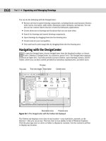
As explained in earlier chapters, you can use the DesignCenter to move named objects,
including xrefs, from one drawing to another. (I cover the DesignCenter in detail in Chapter
26.) To insert an xref from another drawing, press Ctrl+2. Navigate to the drawing and double-
click it to open the list of named objects. Double-click Xrefs to see a list of xrefs in the right
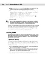
pane, as shown in Figure 19-14.
Figure 19-14: You can use the DesignCenter to insert xrefs into your
drawing.
Double-click the xref that you want to insert. The External Reference dialog box opens (refer
to Figure 19-1) so that you can insert the xref.
The xref log file
If you set the XREFCTL system variable to 1 (by default, it’s set to 0), a copy of all xref activity
for your current drawing is saved in an ASCII text file. You can read the log to troubleshoot
problems that may occur. Figure 19-15 shows part of an xref log file. The log file goes in the
same folder as your drawing and uses your drawing name with the
.xlg filename extension.
This file can become long. Therefore, once in a while, you should delete all or part of the file.
The Reference Manager is a stand-alone program that manages xrefs, images, fonts, and plot
configurations, which are all outside files that are referenced in your drawing. See Chapter
26 for full coverage of the Reference Manager.
The drawing used in the following exercise on managing xrefs, ab19-05.dwg, is in the
Results folder on the CD-ROM.
On the
CD-ROM
Cross-
Reference
27_788864 ch19.qxp 5/22/06 7:40 PM Page 608
609
Chapter 19 ✦ Referencing Other Drawings
Figure 19-15: An xref log file.
STEPS: Managing Xrefs
1. Use ab19-05.dwg from your AutoCAD Bible folder if you did the previous exercise.
Otherwise, open it from the
Results folder of the CD-ROM.
2. Save it as
ab19-06.dwg in your AutoCAD Bible folder.
3. Do one of the following:
• If you have AutoCAD: Choose Modify ➪ Clip ➪ Xref. At the
Select objects:
prompt, pick the xref anywhere. Press Enter. At the Enter clipping option
[ON/OFF/ Clipdepth/Delete/generate Polyline/New boundary] <New>:
prompt, right-click and choose Delete to delete the clip and restore the entire
view of both xrefs.
• If you have AutoCAD LT: If you did the previous exercise and opened
ab19-05
.dwg from your AutoCAD Bible folder, skip this step. If you opened ab19-05.dwg
from the CD-ROM, you have opened an AutoCAD drawing with a clipped xref.
Because AutoCAD LT doesn’t support clipping, you need to reattach the xref.
Copy
ab19-b.dwg from the \Drawings folder and ab19-01.dwg from the
\Results folder (both on the CD-ROM) to your AutoCAD Bible folder. Choose
Insert ➪ External References. Choose
ab19-01 and click Detach. Click Attach.
Select
ab19-01.dwg from your AutoCAD Bible folder and click Open. In the
External Reference dialog box, uncheck the Insertion Point, Scale, and Rotation
Specify On-screen check boxes (if checked) and click OK to attach the xref.
27_788864 ch19.qxp 5/22/06 7:40 PM Page 609
610
Part III ✦ Working with Data
4. Choose Insert ➪ External References. Click the Tree View button. Right-click ab19-b,
the nested xref, and choose Unload.
5. Right-click
ab19-b again. Choose Reload to reload the xref.
6. This time right-click
ab19-01. Choose Bind. In the Bind Xrefs dialog box, choose Insert
and click OK. This action inserts both xrefs (
ab19-01 and ab19-b) as blocks. (Click the
Layer Control drop-down list to see that there are no xref-type layer names.)
7. Save your drawing.
Summary
In this chapter, I covered the techniques that you need to know to work with xrefs. You read
about:
✦ Attaching and overlaying xrefs
✦ Opening an xref in its own window
✦ Editing xrefs and blocks from within the drawing in which they appear
✦ Clipping xrefs so that only the portion you need to see is displayed
✦ Setting spatial and layer indexes to speed up the display of large xrefs
✦ Deleting, unloading, and reloading xrefs
✦ Binding an xref to make it part of your drawing
In the next chapter, I cover database connectivity, which enables you to access outside
databases.
✦✦✦
27_788864 ch19.qxp 5/22/06 7:40 PM Page 610
20
20
CHAPTER
Working with
External Databases
T
he AutoCAD database connectivity feature enables you to com-
municate with an external database from within AutoCAD.
AutoCAD LT does not include the database connectivity feature.
This entire chapter applies to AutoCAD only.
Database connectivity is a powerful way to link drawing objects with
data and is more flexible than using block attributes. With database
connectivity, you can link data in an external database to any object
in a drawing. In this chapter, I show you that database connectivity
does not have to be as difficult as it often sounds.
Many AutoCAD users maintain databases separately from their draw-
ings. Now you can work directly with your data by linking the rows of
the database tables to objects in your drawings. The drawing objects
thus become intelligent and carry these links with them in the drawing.
You can also change data, such as a price or a part number, from within
AutoCAD and have that change automatically applied and available in
all drawing objects that are linked to that database item. Finally, you
can create labels in your drawing, based on the data in the database.
Understanding External Database
Access
Many organizations maintain extensive databases of objects that are in
your AutoCAD drawings. Manufacturers maintain databases of parts,
offices maintain databases of furniture, and so on. You need to keep
your drawings and the databases synchronized so that the information
in the databases and in the drawings is always accurate and up to date.
The linking of databases and AutoCAD drawings is referred to as
external database access. External database access enables you to:
✦ Create links between AutoCAD drawing objects and the external
data
✦ View data in external databases
✦ Edit data in external databases
✦ Display external database data in your drawing
✦✦✦✦
In This Chapter
Understanding
database connectivity
Preparing for database
connectivity
Connecting to a
database
Linking data to drawing
objects
Creating labels
Querying the database
Working with query
files
✦✦✦✦
28_788864 ch20.qxp 5/22/06 7:32 PM Page 611
612
Part III ✦ Working with Data
The database connectivity feature works with the following databases:
✦ Microsoft Access
✦ dBASE
✦ Microsoft Excel
✦ Oracle
✦ Paradox
✦ Microsoft Visual FoxPro
✦ SQL Server
After you configure a database, as explained later in this chapter, you can access the data in
the database even if you don’t have the database program that created the data.
A database is a set of related information, usually maintained by a database management sys-
tem (DBMS) — an application that manages databases. A database is stored in the form of a
table that contains rows and columns. A row, also called a record, contains one element of
data, such as the information for one desk. A column, also called a field, contains the
attributes of the data, such as the price.
Table 20-1 shows the first three rows of the database used as an example in this chapter.
Table 20-1: A Simple Database Table
Part Number Description Dwg Size Made/Purchased Units
8665-023-012 Welding Wire —0.030 StainlessB B P FT
8665-023-013 Weld Rod—0.045 Dia Stainless Steel B P FT
8665-023-014 Welding—Rod 0.045 Dia S.S. B P FT
A relational database is a type of database that contains a collection of tables. Each table rep-
resents a set of data for a defined use.
Structured Query Language (SQL — pronounced sequel or S-Q-L) was created to provide users
with a database language that would be applicable across multiple platforms and database-
management programs.
Some database systems use environments, catalogs, schemas, and tables to create a hierarchy
of database objects. A database object is simply the term used to specify any of the following
SQL2 objects: environment, catalog, schema, or table.
✦ The environment is the entire database system — the DBMS, the databases it can
access, the users, and the programs that can access those databases.
✦ A catalog is a collection of schemas and has the same name as the folder where the
database is located.
✦ A schema is a set of tables and other database components. It has the same name as
the catalog subfolder where the database tables reside.
28_788864 ch20.qxp 5/22/06 7:32 PM Page 612
613
Chapter 20 ✦ Working with External Databases
You don’t need to work with these concepts if your database system does not require or
specify it. AutoCAD can connect to an individual table or to a collection of tables stored in an
environment, catalog, or schema.
Preparing for Database Connectivity
Database connectivity involves several components that you need to prepare in advance.
When they are in place, the connection should go smoothly. In this section, I explain the nec-
essary preparation steps.
The basic steps for starting to work with database connectivity are as follows:
1. Make sure that you have the ODBC Data Source program from Microsoft.
2. Arrange your database tables into catalogs (folders) and schemas (subfolders) appro-
priate for your application, if necessary.
3. Configure the appropriate database driver using Microsoft’s ODBC (Open Database
Connectivity) or OLE DB programs.
4. Configure your data source from within AutoCAD.
5. Start the dbCONNECT command.
6. Establish a user access name and password, if required by the database system.
7. Connect to your data source.
8. Open the Data View window containing your data table.
9. Edit the data, if desired.
10. Link database rows to objects in your drawing.
11. Create labels based on the data in your drawing, if desired.
Organizing the database structure
To connect to a database, you need to know the type of database-management system that
created the database and the structure of the database itself, along with the folders that con-
tain that structure.
In the following exercise, you create a simple structure for a Microsoft Access database table.
In this chapter, you cannot do the later exercises without doing the earlier ones. The later
exercises depend on the setup and configuration that you create in the earlier exercises.
The file used in the following exercise on creating the structure for the database, ab20-prt
.mdb, is in the Drawings folder on the CD-ROM.
On the
CD-ROM
Note
28_788864 ch20.qxp 5/22/06 7:32 PM Page 613
614
Part III ✦ Working with Data
STEPS: Creating the Structure for the Database
1. Right-click Start on the task bar. Choose Explore to open Windows Explorer.
2. If your
AutoCAD Bible folder is not displayed in the Folders window, click the plus sign
(+) next to the drive containing the
AutoCAD Bible folder.
3. Click the
AutoCAD Bible folder and choose File ➪ New➪ Folder from the Explorer
menu. A new folder appears in the right window, called
New Folder. Type Databases ↵
to rename the folder.
4. If necessary, in the Folders window, click the plus sign to open the
AutoCAD Bible
folder. You should see the new Databases folder. (If not, press F5 to refresh the
Explorer view.)
5. From the CD-ROM, copy
ab20-prt.mdb to the Databases folder that you just created.
(Be sure to choose the
ab20-prt.mdb file, not the ab20-prt.xls file.) The .mdb file is
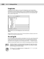
a database of parts. Figure 20-1 shows this database.
6. Because this file is coming from a CD-ROM, you may need to change its read-only prop-
erty. Still in Explorer, right-click
ab20-prt.mdb and choose Properties from the menu.
Uncheck Read-Only and click OK.
7. Click the Close button of Explorer to close it.
Figure 20-1: The Microsoft Access database.
Thanks to Gary Morris of the Dexter Company, Fairfield, Iowa, for this database.
Configuring a data source
To start working with external databases, you must tell AutoCAD how to communicate with
your database, called a data source. AutoCAD uses ODBC and OLE DB for this communication.
AutoCAD provides a sample Microsoft Access file, called
db_samples.mdb in AutoCAD’s
Sample folder, that you can work with to get started.
28_788864 ch20.qxp 5/22/06 7:32 PM Page 614
615
Chapter 20 ✦ Working with External Databases
First, you must install and configure the ODBC Data Source Administrator. To check if the
ODBC Data Source Administrator is installed on your computer, open the Control Panel by
choosing Start ➪ Settings ➪ Control Panel (or as required by your operating system), and look
for one of the following items:
✦ ODBC Data Sources (32-bit) or Data Sources (ODBC)
✦ Administrative Tools➪ Data Sources (ODBC)
To check if you have the required drivers installed, double-click the ODBC item. In the ODBC
Data Source Administrator dialog box, you’ll see a list of database application drivers. Check to
see that your database application is listed. A database driver contains information about how
to connect to your database. In most cases, your operating system will include the ODBC
Administrator. If you don’t have the ODBC 32-bit Administrator, you need to install the Microsoft
ODBC Driver Pack. The ODBC Driver Pack 3.0 (or later) is free from the Microsoft Web site at
The MDAC (Microsoft Data
Access Components) 2.8 download should provide you with everything you need.
The instructions to set up the database vary according to the drivers that you use. The
AutoCAD online help contains help on all supported databases. Look in Help ➪ Help and click
the Contents tab. Double-click Driver and Peripheral Guide and then Configure External
Databases. Click the Procedures tab and choose the link for your database.
To set up your database using ODBC, follow these steps:
1. From the Windows task bar, choose Start➪ Settings ➪ Control Panel (or Start ➪ Control
Panel).
2. Double-click the Administrative Tools icon, then double-click the Data Sources (ODBC)
item. Windows opens the ODBC Data Source Administrator dialog box, shown in
Figure 20-2.
3. Click the User DSN tab if it isn’t already displayed. Choose Add.
4. In the Create New Data Source dialog box, choose the driver appropriate for your
database and click Finish.
Figure 20-2: Use the ODBC Data
Source Administrator dialog box,
accessed from the Windows
Control Panel, to choose a database
driver to connect to your database.
28_788864 ch20.qxp 5/22/06 7:32 PM Page 615
616
Part III ✦ Working with Data
5. In the ODBC Setup dialog box, which is now titled with the name of the driver that you
chose (for example, ODBC Microsoft Access Setup), type a name for your data source
in the Data Source Name text box. You can also add a description. In general, this name
refers to your database program, not the individual database file.
6. Click Select and navigate to the folder containing your database. Choose the database
file and click OK.
7. Click OK again in the Setup dialog box.
8. In the ODBC Administrator dialog box, your data source is listed with its appropriate
driver. Click OK. Close the Administrative Tools window and the Control Panel.
You’re now ready to configure your database from within AutoCAD. Follow these steps:
1. Choose Tools➪ Palettes➪ dbConnect to open the dbConnect Manager palette and dis-
play the dbConnect menu.
2. From the menu, choose dbConnect➪ Data Sources➪Configure. (The dbConnect menu
appears when you start dbConnect.) In the Configure a Data Source dialog box, type a
name representing your database file. Click OK.
3. On the Provider tab of the Data Link Properties dialog box, choose Microsoft OLE DB
Provider for ODBC drivers. Click Next.
4. From the drop-down list on the Connection tab, choose the name of the data source
that you used in the ODBC Setup dialog box, as shown in Figure 20-3.
Figure 20-3: Use the Data Link Properties
dialog box to configure your data source
within AutoCAD.
28_788864 ch20.qxp 5/22/06 7:32 PM Page 616
617
Chapter 20 ✦ Working with External Databases
5. For server-based databases, enter the user name and password.
6. Click Test Connection. You should see a message saying
Test Connection Succeeded.
(If not, check your settings as well as the spelling and case of the name of the data
source.) Click OK.
7. Click OK in the Data Link Properties dialog box.
You’re now ready to establish a connection between a database and an AutoCAD drawing.
The drawing used in the following exercise on configuring a Microsoft Access database,
ab20-a.dwg, is in the Drawings folder on the CD-ROM. This exercise requires that you
have completed the steps in the previous exercises.
STEPS: Configuring a Microsoft Access Database
1. From the task bar, choose Start➪ Settings➪ Control Panel (or Start ➪ Control Panel).
Double-click the Administrative Tools icon, then double-click the Data Sources (ODBC)
icon. (Your item may have a slightly different name.)
2. On the User DSN tab of the ODBC Data Source Administrator dialog box, choose Add.
3. In the Create New Data Source dialog box, choose Microsoft Access Driver. Choose
Finish.
4. In the Data Source Name text box of the ODBC Microsoft Access Setup dialog box, type
ab20-Access.
5. Click Select and navigate to your
AutoCAD Bible\Databases folder (which you created
in the previous exercise). Choose
ab20-prt.mdb and click OK.
6. Click OK twice more to exit the ODBC Data Source Administrator.
7. Close the Administrative Tools and Control Panel windows.
8. Open AutoCAD. Open
ab20-a.dwg from the CD-ROM. Save it as ab20-01.dwg in your
AutoCAD Bible folder.
9. Choose Tools➪ Palettes➪ dbConnect to open the dbConnect Manager palette and dis-
play the dbConnect menu. From the menu, choose dbConnect➪ Data Sources➪
Configure. In the Configure a Data Source dialog box, type ab20-prt. Click OK.
10. On the Provider tab of the Data Link Properties dialog box (which opens automati-
cally), choose Microsoft OLE DB Provider for ODBC Drivers. Click Next.
11. From the upper drop-down list, choose ab20-Access.
12. Click Test Connection. You see a message saying
Test Connection Succeeded. Click OK.
13. Click OK in the Data Link Properties dialog box.
14. Keep
ab20-01.dwg open for the next exercise.
On the
CD-ROM
28_788864 ch20.qxp 5/22/06 7:32 PM Page 617
618
Part III ✦ Working with Data
Connecting to Your Database
After you configure the database connectivity feature, you’re ready to connect to your
database. Here you actually start making connections between objects in your drawing and
rows in your database.
Before connecting to your database, you should think about the relationship between the
drawing and the database. For example, you should decide:
Connecting to an Excel Spreadsheet
If you have a database in Excel and want to practice working with Excel, you may use the Excel
spreadsheet database on the CD-ROM. Here’s how:
1. Follow the steps in the exercise “Creating the Structure for the Database.” In Step 5, copy the
ab20-prt.xls file instead of the .mdb file. If necessary, uncheck the read-only property as
described in Step 6.
2. Double-click the Administrative Tools, then Data Sources (ODBC) icons in the Control
Panel to open the ODBC Data Source Administrator dialog box.
3. On the User DSN tab of the ODBC Data Source Administrator dialog box, choose Add.
4. In the Create New Data Source dialog box, choose Microsoft Excel Driver (
*.xls) and
choose Finish.
5. In the ODBC Microsoft Excel Setup dialog box, type ab Excel as the Data Source Name.
(If you want, type a description.)
6. Click Select Workbook. Use the dialog box to choose the
AutoCAD
Bible\databases\ab20-prt.xls worksheet. Click OK three times and close the
Control Panel.
7. Open AutoCAD. Open
ab20-a.dwg from the CD-ROM. Save it as ab20-01.dwg in your
AutoCAD Bible folder. Choose Tools➪ dbConnect.
8. Choose dbConnect➪ Data Sources➪ Configure. In the Configure a Data Source dialog
box, type ab Excel. Click OK.
9. On the Provider tab of the Data Link Properties dialog box, choose Microsoft OLE DB
Provider for ODBC drivers. Click Next.
10. From the upper drop-down list, choose ab Excel.
11. Click Test Connection. At the
Test Connection Succeeded message, click OK.
12. Click OK in the Data Link Properties dialog box.
You can continue the rest of the exercises, starting from “Connecting a Database to a Drawing,”
without change.
The equivalent of a table in Excel is a named range. You need to open your worksheet, select all
of the data, and type a range name in the Name box at the left end of the Formula bar. To set up
the database, put a field name in the first row of each column.
28_788864 ch20.qxp 5/22/06 7:32 PM Page 618
619
Chapter 20 ✦ Working with External Databases
✦ If the data is to be in one database with many tables or in several separate databases
✦ Which data you want to link to which drawing objects
✦ If several drawing objects will be linked to one row or only one object will be linked
to a row
✦ If you want a drawing object linked to more than one row
✦ Which column(s) will identify unique records
You’re now ready to connect your database to your drawing.
Connecting a database to a drawing
You use the dbConnect Manager, shown in Figure 20-4, to perform all of the connectivity func-
tions. The dbConnect Manager has its own toolbar, which becomes active when you choose a
connected data source. All configured data sources are listed.
Figure 20-4: The dbConnect Manager.
You can dock and undock the dbConnect Manager like any palette. You can also resize it by
dragging its right border left or right. After you open the dbConnect Manager, you see a list of
open drawings and configured data sources.
Follow these steps to connect an external database to a drawing:
1. Open the drawing that you want to connect with a database.
2. Choose Tools➪ Palettes➪ dbConnect (or press Ctrl+6) to open the dbConnect
Manager.
3. Right-click the data source to which you want to connect. (The names listed come from
the names that you entered when you configured the data source in AutoCAD.) Choose
Connect.
AutoCAD lists the database tables associated with the data source. The entire database struc-
ture is now connected, and you can view and work with the database data within AutoCAD. In
order to do the following exercise, you must have completed the previous two exercises.
28_788864 ch20.qxp 5/22/06 7:32 PM Page 619
620
Part III ✦ Working with Data
STEPS: Connecting a Database to a Drawing
1. You should have ab20-01.dwg open from the previous exercise.
2. Choose Tools➪ Palettes ➪ dbConnect to open the dbConnect Manager.
3. Right-click
ab20-prt and choose Connect. The dbConnect Manager lists the database
table
PART NO.
4. Save the drawing. Keep it open. Continue to the next exercise.
Opening a data table
After your database is connected, you choose the database table with which you want to work.
If necessary, click the plus sign next to the desired database to see the actual database files that
are available. The database file also displays a plus sign. If necessary, click it to display the
database tables within the database file. (A database file can contain more than one table.)
You can view or edit a table in the Data View window:
✦ View the data when you have no need to edit it. To view your data, right-click the table
that you want to view and choose View Table.
✦ Edit the data when you need to make changes to your database from within AutoCAD.
To edit your data, right-click and choose Edit Table.
To view or edit a table, select the table. Choose View Table or Edit Table from the dbConnect
Manager’s toolbar. You can also right-click the table and choose View Table or Edit Table from
the shortcut menu.
Figure 20-5 shows the Data View window when you choose Edit Table. (When you choose
View Table, you see the same view but the data cells are gray.)
Figure 20-5: The Data View window displays your data.
Grid header Column header
Record header
28_788864 ch20.qxp 5/22/06 7:32 PM Page 620
621
Chapter 20 ✦ Working with External Databases
The Data View window presents your data in a grid, with each piece of data in a cell, like a
spreadsheet. You can use the scroll bars to scroll through the data. To the left of the horizon-
tal scroll bar, you can use the arrows to move from record to record. The far left and right
arrows with a vertical bar move you to the first and last record, respectively.
When you open the Data View window, a new Data View item appears on the AutoCAD menu.
You can temporarily change the way the data is displayed. These changes are discarded after
you close the Data View window; they don’t affect the data file in your database. Here are
your options:
✦ Resize a column: You may find that your data doesn’t completely display in a column
or that columns don’t all appear in the window. Click the grid line to the right of any
column header and drag it to the left or right. You can also resize the entire Data View
window by dragging on its sides or bottom.
✦ Move a column: You can change the order of the columns by moving a column to
another location. Click the column’s header to select the column. Then click and drag
the column to the location you want. A red vertical line indicates where the column
will land.
✦ Hide a column: You can hide a column with which you don’t need to work. This is
especially helpful if you have many columns and can’t fit them easily on the screen.
Click the column’s header to select the column. Then right-click the column header and
choose Hide. To redisplay the column, right-click any column header and choose
Unhide All.
✦ Sort records: You can sort records in ascending (low to high) or descending (high to
low) order. Sorting helps you to more easily find the records that you want. Right-click
any column header and choose Sort to open the Sort dialog box, shown in Figure 20-6.
In the Sort By drop-down list, choose the column that you want to sort by first. Then
choose Ascending or Descending. This column may have duplicate records. If so, you
may want to choose a secondary column for sorting in the Then By drop-down list.
Choose Ascending or Descending for the secondary column. AutoCAD will then sort
first by the first column and then by the secondary column. You can choose up to five
columns to sort by.
✦ Freeze one or more columns: Freezing one or more contiguous columns moves them
to the left column. Select the columns by clicking their column headers. (Press Ctrl to
select additional columns. You can also select one column, press Shift, and select
another column to select all of the columns in-between.) Then right-click a selected col-
umn and choose Freeze. To return the column to its original location, right-click and
choose Unfreeze All.
✦ Align text: You can align text in a column or columns. By default, columns use the
Standard alignment, which right-aligns numbers and left-aligns everything else. Select a
column or columns by clicking the column header(s), right-click any column header,
and choose Align. Then choose Standard, Left, Center, or Right.
✦ Format text: You can format the font, font style, font size, effects (strikethrough and
underline), and color of the text in the Data View window. Note that, unlike the other
changes previously listed, these changes continue to affect the formatting of the Data
View window the next time you open a Data View window. Choose Data View➪ Format
to open the Format dialog box. Choose the formatting that you want and then click OK.
28_788864 ch20.qxp 5/22/06 7:32 PM Page 621
622
Part III ✦ Working with Data
To get the Data View window out of the way, you can dock it. Right-click in the Data View
window’s toolbar area and choose Allow Docking. Then drag the window to the right edge of
your screen (assuming your dbConnect window is on the left side of your screen).
Figure 20-6: Use the Sort dialog box to
temporarily sort your data in the Data View
window.
Although you can scroll through your data’s records, if you have many records, this can be
time-consuming. You can search for a particular record by specifying a desired value. Follow
these steps:
1. Select any cell in the column that contains the record that you want to find. If you want
to search the entire column, choose the first or last cell in the column.
2. Choose Data View➪ Find to open the Find dialog box, shown in Figure 20-7. (You can
also right-click any cell in the column and choose Find.)
Figure 20-7: The Find dialog box.
3. In the Find what box, type a value (text, numbers, or a combination). Choose to search
either Up (from the selected cell to the first record) or Down (from the selected cell to
the last record). If desired, choose Match Case. Then click Find Next to find the next
instance of the value. Continue to click Find Next to move to the next matching record.
If you want, you can copy your formatting, including sorting, to the Clipboard and paste it
into your DBMS. To do this, select the records that you want to export. To export the entire
database, click the grid header. Then right-click any cell and choose Copy. Open your DBMS
and click Paste from the Standard toolbar.
Tip
Tip
28_788864 ch20.qxp 5/22/06 7:32 PM Page 622
623
Chapter 20 ✦ Working with External Databases
In the following exercise, you practice using the Data View window.
STEPS: Working with the Data View Window
1. Ab20-01.dwg should still be open from the previous exercise. If there’s a plus sign next
to
ab20-prt, click it to display the “PART NO” table. The dbConnect Manager should
look similar to Figure 20-8.
Figure 20-8: Displaying a database table in the
dbConnect Manager palette.
2. Right-click the table icon and choose Edit Table. The Data View window opens.
3. From the menu, choose Data View➪Format. (A new Data View menu item has appeared.)
In the Format dialog box, choose Arial as the font and 10 as the font size. Click OK.
4. The columns are too wide and you can’t see all of them. Click the grid line to the right
of the PART_NO column and drag it to the left so that the width of the column just fits
the width of the part numbers. Do the same with the other columns. To access the right
grid line of the last column (UNITS), expand the right side of the entire window. Then
resize the UNITS column and shrink the Data View window to fit. Your Data View table
should look like Figure 20-9.
Figure 20-9: The Data View table after some formatting.
28_788864 ch20.qxp 5/22/06 7:32 PM Page 623
624
Part III ✦ Working with Data
5. Right-click the PART_NO column’s header and choose Align ➪ Right to right-align the
first column.
6. To practice moving around the table, click the right-most arrow at the bottom of the
Data View window (to the left of the horizontal scroll bar) to move to the last record.
Use the vertical scroll bar to scroll through the database and get an idea of its con-
tents. Click any cell. Click a row header to select an entire row. Click a column header
to select an entire column.
7. To sort the records by description and help you to find all of the angles, right-click
the DESCRIPTION column header and choose Sort. In the Sort dialog box, choose
DESCRIPTION from the Sort By drop-down list, and then click Ascending (if it’s not
already selected). Because there are a number of duplicate records in the DESCRIPTION
column, choose PART_NO in the Then By drop-down list, which should also be sorted
in ascending order. Click OK. AutoCAD sorts the data by description, and then by part
number.
8. Say that you want to find part number 9003-242-001. Right-click the top cell in the
PART_NO column. Choose Find. In the Find dialog box, type 9003-242-001 and choose
Down in the Direction section. Click Find Next. AutoCAD highlights the cell containing
that part number.
9. Close the Find dialog box and save your drawing. Keep it open for the next exercise.
Editing data in the Data View window
After you open your data in Edit mode, you can easily edit the data. You can change the value
of any record. You can add or delete records to reflect new or deleted objects in your draw-
ing. Changing a record is as simple as selecting a cell and typing a new value.
To add a new record, right-click any record (row) header and choose Add New Record.
AutoCAD opens up a space for a new record at the end of the list of records. Type the data for
the new record, tabbing from column to column. (You can also use the right-arrow key to
move to the next column.)
To delete a record, right-click the record header of the record that you want to delete, select-
ing the entire record. Choose Delete Record. You need to confirm the deletion twice in the
dialog boxes that pop up.
You should not use the DBMS to edit a database separately while it is connected to
AutoCAD. If you do edit the database table outside of AutoCAD during an AutoCAD connec-
tion, you may get system crashes or corrupted data. If you need to edit the database using
the DBMS, make sure that you disconnect the table first in the dbConnect Manager palette.
AutoCAD doesn’t save your changes until you commit them. To save your changes, right-click
the grid header — the cell at the top-left corner of the Data Table window — and choose
Commit. To discard your changes, choose Restore, which restores the original values of the
database when you opened the Data Table window.
STEPS: Editing Data
1. With ab20-01.dwg and the Data Table window still open from the previous exercise,
the part number that you found in the previous exercise (9003-242-001) should still be
highlighted. If not, find it following the instructions in Step 8 of the previous exercise.
Caution
28_788864 ch20.qxp 5/22/06 7:32 PM Page 624
625
Chapter 20 ✦ Working with External Databases
2. Note that the MADE/PUR column indicates that this horizontal angle is purchased. Say
that the company has decided to make this angle. Click the P in the MADE/PUR column
of the 9003-242-001 record and type M.
3. To add a record, right-click any record (row) header and choose Add New Record.
AutoCAD moves you to the end of the records with a space for a new record. Type the
following, tabbing between each column:
8665-023-018 WELDING ROD - .05 DIA S.S. B P FT
4. I don’t recommend saving the changes to the database because you may want to do
this exercise again in the future. Right-click the grid header (in the upper-left corner of
the database) and choose Restore. AutoCAD closes the Data Table.
5. Keep the drawing open for the next exercise.
Linking Data to Drawing Objects
The main purpose of using data connectivity is to link data to objects in your drawing. A row
of data contains information about the real-life object that objects in your drawing represent.
By connecting a row of data to an object or objects in your drawing, you can:
✦ View information about the real-life object while in your drawing, such as price, source,
next service date, and so on.
✦ Update a drawing based on changes in the database or vice versa, to keep your draw-
ings and your database synchronized.
✦ Display a label containing data information next to a drawing object.
Creating a link template
When AutoCAD creates a link, it associates an object or objects with a row in your database.
To do so, AutoCAD needs to know which field (column) to look in to identify the row. For
example, let’s say you want to link price information to some objects. However, several rows
may contain the same price information. If you provide a field that contains no duplicate
data, AutoCAD can always locate the required row. If AutoCAD finds two rows with the same
data, it accesses the first row. It makes sense, therefore, to be careful to choose a column that
contains no duplicate values. If your data doesn’t contain such a column, most DBMSs can
create an index field that ensures that each row is unique.
A link template identifies which fields are associated with a link between the data and a draw-
ing object. A link template also identifies your database. After you create a link template, you
can open your data directly from the template, which is listed in the dbConnect window.
If you want to associate data from more than one database table to a single object, you may
need to create more than one link template for an object.
To create a link template, follow these steps:
1. Choose dbConnect ➪ Templates➪ New Link Template.
2. If you haven’t already opened a data table, AutoCAD opens the Select Data Object dia-
log box. Choose a table and click Continue.
28_788864 ch20.qxp 5/22/06 7:32 PM Page 625
626
Part III ✦ Working with Data
3. In the New Link Template Name text box of the New Link Template dialog box, shown in
Figure 20-10, type a name for the link template. AutoCAD assigns an automatic name
using the name of the data source and Link1, Link2, and so on. You can use that name or
type your own. If you have a previous link template that you want to use as a basis for
the new template, choose it from the Start with Template drop-down list. Click Continue.
Figure 20-10: The New Link
Template dialog box.
4. In the Link Template dialog box, check a key field. If the key field that you choose con-
tains any duplicate rows, you should choose a second key field.
5. Click OK. AutoCAD creates the link template, which is added to the dbConnect Manager
palette beneath the current drawing.
You’re now ready to link data with drawing objects.
If the structure of your database changes dramatically, you may need to edit a link template.
For example, a field that contained no duplicate entries might now contain some. Other
changes requiring a change in the template would be a change in the name or length of a
field. To edit a link template:
1. Connect to the desired database table.
2. Choose dbConnect ➪ Templates➪ Edit Link Template.
3. In the Select a Database Object dialog box, choose a link template.
4. Click Continue.
5. Check one (or more) of the key fields and click OK.
You can also delete a link template by choosing dbConnect ➪ Templates ➪Delete Link Template.
This exercise requires that you have completed the previous exercises in this chapter.
STEPS: Creating a Link Template
1. Continue with ab20-01.dwg from the previous exercise. In the dbConnect window,
right-click
“PART NO” and choose Edit Table to open the Data Table window.
2. Choose dbConnect ➪ Templates➪ New Link Template.
3. Select the PART_NO table and click Continue.
28_788864 ch20.qxp 5/22/06 7:32 PM Page 626
627
Chapter 20 ✦ Working with External Databases
4. In the New Link Template dialog box, use AutoCAD’s suggested name, _PART_NO_Link1.
Click Continue.
5. In the Link Template dialog box, check PART_NO. This column contains no duplicate rows.
6. Click OK to return to the drawing. You see the new link template with a chain-link icon
in the dbConnect Manager palette just under the name of the open drawing.
7. Save your drawing. Leave it open to continue with the next exercise.
You’re now ready to link drawing objects to your database.
Creating a link
You can link a drawing object to as many records in a database as you want, and you can link
one database record to several drawing objects. For example, you may want to link a record
containing part-number information to the part in the drawing. However, that part may be
made up of a number of objects, such as lines, arcs, and circles. You can link the record to all
of those objects in your drawing that make up the part. On the other hand, if you have a
database of office equipment, you may attach a row representing telephone numbers and tele-
phones to an object in your drawing representing a phone. However, if someone has a two-line
phone, you may need to attach two rows to that one telephone object in your drawing.
Here’s how to create a link:
1. Open a Data View window that has a defined link template and choose a link template
from the Select a Link Template drop-down list at the top of the window.
2. Select one or more records that you want to link to your drawing.
3. Choose Data View➪ Link and Label Settings➪ Create Links.
4. Choose Data View➪ Link! (You can also choose Link in the Data View window.)
5. AutoCAD returns you to your drawing. Select one or more objects and press Enter to
end object selection.
AutoCAD provides a message on the command line, for example:
1 Record(s) linked with 1
Object(s). You now have a link between your data and your drawing.
If you create a link between a drawing object and a row and in a later session of AutoCAD
edit that object without connecting to the database table, the link information may become
corrupted.
You can delete a link by selecting a linked object and right-clicking in the drawing area. From
the shortcut menu, choose Link ➪ Delete Link.
Viewing linked objects and rows
After you create a link, you need to be able to see which rows are linked to which objects
before you can make decisions regarding either the data or the drawing objects. You can view
the link from either side. That is, you can select an object and see which row or rows it is
linked to or you can select a row and have AutoCAD select the object or objects to which it’s
linked. In both cases, you need to have a Data View table displayed.
Caution
28_788864 ch20.qxp 5/22/06 7:32 PM Page 627
628
Part III ✦ Working with Data
✦ To find out which row an object is linked to, select one or more objects. Then choose
Data View➪ View Linked Records. AutoCAD highlights the row or rows that are linked
to the selection set of objects. Later in this section, I explain how to customize the dis-
play of a row or rows.
✦ To find out which object a row is linked to, select one or more records. Choose Data
View➪ View Linked Objects. AutoCAD pans, zooms (or does both so that you can see
the objects in the center of the screen), and selects them. Later in this section, I explain
how to customize the panning and zooming.
You’ll find that the Data View window obscures your drawing. You can drag it to the bottom
of your screen, resize it, or dock it.
When you use View Linked Objects, the selected objects form a selection set. You can then
use the results with other commands that allow prior selection of objects. For commands
that you must execute before selecting objects, type p ↵ at the Select objects: prompt
to use the Previous option and get the selection set.
If you want to move from object to object or row to row to view your links one after another,
you should use Auto-View. The Auto-View feature automatically highlights either objects when
you choose a row in the Data View window or rows when you choose objects in your drawing.
However, you can work from only one side of the equation—either rows or objects —at a
time. Here’s how it works:
✦ To automatically select linked objects when you select a row, choose Data View ➪
AutoView Linked Objects (or use the AutoView Linked Objects in Drawing button in the
Data View window). Then select a record (or records) by clicking the row header(s) in
the Data View window. AutoCAD highlights the linked objects. You can continue to
select different records to highlight their linked objects. Choose Auto-View Linked
Objects (or click the button) again to turn off Auto-View.
✦ To automatically select linked rows when you select an object, choose Data View➪
AutoView Linked Records (or use the AutoView Linked Records in Data View button in
the Data View window). Then select an object (or objects). AutoCAD highlights the
linked rows. You can continue to select different objects to highlight their linked rows.
Choose Auto-View Linked Records (or click the button) again to turn off Auto-View.
When you’re in Auto-View, you can’t select records. If you click another record’s row header
to create a link, AutoCAD just tells you
0 Object(s) found matching 0 selected
Record(s). Be sure to turn off Auto-View when you go on to another task.
You can customize how AutoCAD displays linked rows and how AutoCAD pans (AutoPan) and
zooms (AutoZoom) to display selected objects. Choose Data View➪ Settings. In the Record
Indication Settings section of the Data View and Query Options dialog box, choose either
Show Only Indicated Records or Show All Records —Select Only Indicated Records (the
default). You can also choose the highlight color. To set AutoPan and AutoZoom, use the
AutoPan and Zoom section of the same dialog box. Uncheck Automatically Pan Drawing and
Automatically Zoom Drawing if you don’t want this feature. When Automatically Zoom
Drawing is checked, you can also choose a zoom percentage. You can choose from 20 to 90
percent. The default, 50 percent, means that the height (or width, if less) of the extents of the
zoomed area is 50 percent of the drawing area. Click OK after you finish using the dialog box.
Tip
28_788864 ch20.qxp 5/22/06 7:32 PM Page 628
629
Chapter 20 ✦ Working with External Databases
Editing links
After you create links in your drawing, you need to be careful how you edit your database
from within AutoCAD. For example, you don’t want to inadvertently delete a record that is
linked to an object.
You may need to edit the key value assigned to a linked object. For example, your company
may change the part-numbering scheme or you may have simply assigned the wrong part
number to an object. The Link Manager enables you to edit key values for linked objects.
Follow these steps:
1. Choose dbConnect ➪ Links➪Link Manager to open the Link Manager, shown in Figure
20-11. You can also select a linked object, right-click in the drawing area, and choose
Link ➪ Link Manager.
2. At the
Select an object: prompt, select an object.
3. In the Link Manager, choose the Link Template that you want to work with from the
drop-down list.
Figure 20-11: The Link Manager enables you to
edit key value data for its linked object.
4. In the Value column, type a new value, such as a new part number.
5. Click OK.
AutoCAD updates the link.
You can also click the Delete button to delete the object’s link.
Exporting link information
You can export a list of links and the handle of the associated links’ objects. A handle is a
unique name that AutoCAD gives to each object in the drawing. (To view an object’s handle,
select it and choose Tools➪ Inquiry ➪ List.) You can export the reports in the same format as
your database (called the native format) or in space- or comma-delimited formats. You might
use these reports to keep track of how many objects are linked to a row because the exported
information tells you how many instances a drawing contains of a record in a database. For
example, if your database lists configurations of desktop computers and you’ve linked each
person’s computer to the appropriate row in the database, the list will let you know how
many people have each configuration.
28_788864 ch20.qxp 5/22/06 7:32 PM Page 629
630
Part III ✦ Working with Data
Follow these steps to export links:
1. Choose dbConnect ➪ Links➪Export Links.
2. At the
Select objects: prompt, choose the objects whose links you want to export.
When you complete object selection, AutoCAD opens the Export Links dialog box,
shown in Figure 20-12.
You can select the entire drawing (type all ↵ at the Select Objects: prompt) and
AutoCAD finds just the linked objects.
Figure 20-12: The Export Links dialog box.
3. In the Include Fields section, select the fields that you want to include.
4. In the Save In drop-down list, navigate to the folder where you want to save the file.
5. In the Save as Type drop-down list, choose one of the three options: comma-delimited
format, space-delimited format, or native database format.
6. In the File Name text box, type a name for the file.
7. Click Save.
AutoCAD creates the file.
You can use this file to create a schedule of objects with links — but it takes some work. The
comma-delimited format seems to work better than the space-delimited format. You’ll proba-
bly want to edit the file first to remove the object handles. You can open the Multiline In-Place
Text Editor and click Import Text to import the output file into your drawing. You can also
open the output file, copy it to the Clipboard, and paste it into your drawing. The Import Text
method enables you to format the text as you would any multiline text but takes some experi-
menting to set up in the proper columns. You can also import the file into a spreadsheet and
format it before importing it into your drawing. If you used the native format, you can open it
in your DBMS, format it, and import it into your drawing. (See Chapter 27 for more informa-
tion on importing files.)
STEPS: Creating and Viewing Links
1. You should have ab20-01.dwg open from the previous exercise. The Data View window
is open with the database visible. The _PART_NO_Link1 link template is current. You
can see the entire drawing in Figure 20-13.
Tip
28_788864 ch20.qxp 5/22/06 7:32 PM Page 630
631
Chapter 20 ✦ Working with External Databases
2. To locate the record that you need, in the Data View window click the left-most arrow
next to the horizontal scroll bar to move to the first record. Choose Data View ➪ Find.
In the Find dialog box, type 9003-242-001. The direction should be down. Click Find
Next. AutoCAD finds the record. Close the Find dialog box by clicking its Cancel button.
3. Click the row’s header (the arrow to the left of the row) to select the entire row.
4. Choose Data View➪ Link and Label Settings➪ Create Links. The Create Links menu
item may already be checked.
5. Choose Data View➪ Link!
6. AutoCAD returns you to your drawing. Use the Zoom Window to zoom into the area
marked
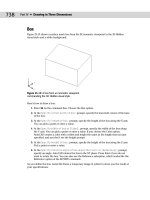
1 in Figure 20-13.
Figure 20-13: This drawing of a base assembly for a commercial
washing machine has objects that can be linked to the database
of parts.
Thanks to Robert Mack of The Dexter Company, Fairfield, Iowa, for this drawing.
7. Select all of the objects that make up the angle bracket indicated by 1 in Figure 20-13
(and which the drawing itself labels as 2), as shown in Figure 20-14. Include the two
cyan hidden lines representing the hole, but not the yellow centerline. Don’t select the
vertical line on the right of the angle, which belongs to another part. Press Enter to end
the selection. AutoCAD returns you to the Data View table and displays
1 Record(s)
linked with 8 Object(s)
on the command line.
8. The linked row is highlighted in yellow. Make sure that the arrow cursor in the row
header points to the highlighted row. (AutoCAD moves it down one so that you can work
on the next row.) To view the objects connected to the row, choose Data View ➪View
Linked Objects. Drag the Data View window to the bottom of the screen so that you can
see the drawing (or dock it). The objects that you selected in Step 7 are selected.
1
28_788864 ch20.qxp 5/22/06 7:32 PM Page 631
632
Part III ✦ Working with Data
Figure 20-14: The horizontal angle.
9. In the drawing, press Esc to deselect the objects and remove the grips. To check the
link, click any other row in the Data View window to move the cursor. (Try to position
the Data View window so that you can see both the row you were working with and the
objects you linked it to at the same time.) Choose Data View➪ View Linked Records. At
the
Select objects: prompt, select one of the objects in the angle and press Enter.
AutoCAD displays the correct row in the database.
10. Save your drawing and keep it open for the next exercise.
Creating Labels
A label is multiline text that appears in your drawing, displaying data from a row in your
database. You can choose which fields from the row are displayed. There are two types of
labels:
✦ Attached labels are attached to objects and are displayed with a leader pointing to the
object. If you move the object, the label moves as well. Use an attached label when the
row in the database applies to one or more specific objects in your drawing.
✦ Freestanding labels are independent of any object. You would use freestanding labels
when your database applies to the drawing as a whole.
Creating label templates
Before creating a label, you need to create a label template. A label template specifies which
fields will be included in the label as well as text formatting. Here’s how to create a label
template:
1. Choose dbConnect ➪ Templates➪ New Label Template.
2. In the Select a Database Object dialog box, choose a link template to use with the label
template. Click Continue.
28_788864 ch20.qxp 5/22/06 7:32 PM Page 632