autocad 2007 and autocad lt 2007 bible - phần 7 pdf
Bạn đang xem bản rút gọn của tài liệu. Xem và tải ngay bản đầy đủ của tài liệu tại đây (1.82 MB, 130 trang )
738
Part IV ✦ Drawing in Three Dimensions
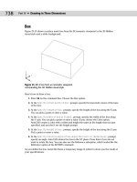
Box
Figure 23-13 shows a surface mesh box from the SE isometric viewpoint in the 3D Hidden
visual style and a white background.
Figure 23-13: A box from an isometric viewpoint
commanding the 3D Hidden visual style.
Here’s how to draw a box:
1. Enter 3d on the command line. Choose the Box option.
2. At the
Specify corner point of box: prompt, specify the lower-left corner of the base
of the box.
3. At the
Specify length of box: prompt, specify the length of the box along the X axis.
You can pick a point or enter a value.
4. At the
Specify width of box or [Cube]: prompt, specify the width of the box along
the Y axis. You can pick a point or enter a value. If you choose the Cube option,
AutoCAD creates a cube with a width and height the same as the length that you just
specified, and you don’t see the height prompt.
5. At the
Specify height of box: prompt, specify the height of the box along the Z axis.
Pick a point or enter a value.
6. At the
Specify rotation angle of box about the Z axis or [Reference]: prompt,
specify an angle. AutoCAD rotates the box in the XY plane. Press Enter if you do not
want to rotate the box. You can also use the Reference suboption, which works like the
Reference option of the ROTATE command.
As you define the box, AutoCAD draws a temporary image in yellow to show you the result of
your specifications.
32_788864 ch23.qxp 5/22/06 7:29 PM Page 738
739
Chapter 23 ✦ Creating 3D Surfaces
Wedge
Figure 23-14 shows a wedge. The prompts are the same as for the box, except that there is no
Cube option. A wedge is half of a box.
Figure 23-14: A wedge from an isometric viewpoint in the
3D Hidden visual style
Here’s how to draw a wedge:
1. Enter 3d on the command line. Choose the Wedge option.
2. At the
Specify corner point of wedge: prompt, specify the lower-left corner of the
base of the wedge.
3. At the
Specify length of wedge: prompt, specify the length of the wedge along the
X axis.
4. At the
Specify width of wedge: prompt, specify the width of the wedge along the Y axis.
5. At the
Specify height of wedge: prompt, specify the height of the wedge along the
Z axis.
6. At the
Specify rotation angle of wedge about the Z axis: prompt, specify an
angle. AutoCAD rotates the wedge in the XY plane. Press Enter if you don’t want to
rotate the wedge.
Pyramid
You can draw pyramids with three- and four-sided bases. A pyramid with a three-sided base
creates a four-sided object called a tetrahedron. You can top the pyramid with a point, a flat
top or, for four-sided bases, a ridge. Figure 23-15 shows the various types of pyramids that
you can draw.
32_788864 ch23.qxp 5/22/06 7:29 PM Page 739
740
Part IV ✦ Drawing in Three Dimensions
Figure 23-15: You can draw all of these pyramidal shapes.
Here’s how to draw the pyramids:
1. Enter 3d on the command line. Choose the Pyramid option.
2. At the
Specify first corner point for base of pyramid: prompt, specify the first
point (any point) on the base.
3. At the
Specify second corner point for base of pyramid: prompt, specify the sec-
ond point on the base.
4. At the
Specify third corner point for base of pyramid: prompt, specify the third
point on the base.
5. At the
Specify fourth corner point for base of pyramid or [Tetrahedron]:
prompt, specify the fourth point on the base or choose the Tetrahedron option (creates
a pyramid with a base of three points).
• If you chose the Tetrahedron option, at the
Specify apex point of tetrahedron
or [Top]: prompt, specify the apex (top point) or choose the Top option.
AutoCAD prompts you for three top points.
• If you specified a fourth base point, at the
Specify apex point of pyramid or
[Ridge/Top]: prompt, specify the apex (top point) or choose the Ridge or Top
options. If you choose the Ridge option, specify the two points for the ridge. If
you choose the Top option, specify the four top points.
Specifying the apex or ridge can be tricky unless you know the absolute coordinates that you
want. You can’t change viewpoints during the command. However, you can easily change the
points later using grips. Another trick is to start any drawing command, such as LINE, before
starting the pyramid. At the
Specify first point: prompt, pick the point that you want to
use for the first base point of the pyramid. Then press Esc to cancel the command. This
leaves that point as the last point specified. Now define the base of the pyramid, using the
same point as the first base point. When you need to specify the apex or ridge, you can use
relative coordinates from the first base point. For example, to create an apex two units
directly over the first base point, specify @0,0,2 for the apex.
32_788864 ch23.qxp 5/22/06 7:29 PM Page 740
741
Chapter 23 ✦ Creating 3D Surfaces
When you use the Top option, AutoCAD provides a rubber-band line from each of the base
corners in turn, letting you use relative coordinates from the base corners. You can also cre-
ate a temporary 2D object before starting the pyramid to frame a ridge or top.
Cone
You can create full or partial cones. Figure 23-16 shows both types, as displayed in the 3D
Wireframe visual style.
Figure 23-16: You can draw full or partial
cones.
Follow these steps to create cones:
1. Enter 3d on the command line. Choose the Cone option.
2. At the
Specify center point for base of cone: prompt, pick the center for the circle
that makes the base of the cone.
3. At the
Specify radius for base of cone or [Diameter]: prompt, specify the radius
for the circle at the base or choose the Diameter option to specify the diameter.
4. At the
Specify radius for top of cone or [Diameter] <0>: prompt, specify the
radius of the top or choose the Diameter option and specify the diameter. If you accept
the default of zero, you get a complete cone. If you specify a radius or diameter, you get
a truncated cone.
You can specify the base’s size to be larger than the top’s size.
5. At the Specify height of cone: prompt, specify the height.
6. At the
Enter number of segments for surface of cone <16>: prompt, specify the
number of mesh segments. A higher number results in a smoother-looking cone.
Note
32_788864 ch23.qxp 5/22/06 7:29 PM Page 741
742
Part IV ✦ Drawing in Three Dimensions
Sphere
Drawing a sphere is quite easy. You just specify the center and radius, and then the number
of segments to display in each direction. Figure 23-17 shows a sphere in the 3D Wireframe
visual style.
Figure 23-17: A sphere.
Here’s how to draw a sphere:
1. Enter 3d on the command line. Choose the Sphere option.
2. At the
Specify center point of sphere: prompt, specify a point.
3. At the
Specify radius of sphere or [Diameter]: prompt, specify the radius, or
choose the Diameter option to specify the diameter.
4. At the
Enter number of longitudinal segments for surface of sphere <16>:
prompt, type the number of north-south lines that you want. A higher number results
in a smoother-looking sphere.
5. At the
Enter number of latitudinal segments for surface of sphere <16>:
prompt, type the number of east-west lines that you want. A higher number results in a
smoother-looking sphere.
The only tricky point with spheres is remembering that the center point is the center in all
three dimensions. If you want to draw a ball on a table, it’s easy to specify the center on the
plane of the tabletop —but you end up with a ball that’s half beneath the table. So plan ahead.
Dome
A dome is the top half of a sphere, as shown in Figure 23-18. The prompts are very similar to
those for a sphere.
Figure 23-18: A dome.
32_788864 ch23.qxp 5/22/06 7:29 PM Page 742
743
Chapter 23 ✦ Creating 3D Surfaces
Follow these steps to draw a dome:
1. Enter 3d on the command line. Choose the Dome option.
2. At the
Specify center point of dome: prompt, specify the center point of the circle
that makes up the base of the dome.
3. At the
Specify radius of dome or [Diameter]: prompt, specify the radius or use the
Diameter option to specify the diameter.
4. At the
Enter number of longitudinal segments for surface of dome <16>: prompt,
type the number of north-south lines that you want. A higher number results in a
smoother-looking dome.
5. At the
Enter number of latitudinal segments for surface of dome <8>: prompt,
type the number of east-west lines that you want. A higher number results in a
smoother-looking dome. Notice that the default is 8 instead of 16 for the sphere
because you’re drawing only half of a sphere.
Dish
A dish is the bottom half of a sphere, as shown in Figure 23-19. Actually, a bowl would be a
better name for it.
Figure 23-19: A dish.
Follow these steps to draw a dish:
1. Enter 3d on the command line. Choose the Dish option.
2. At the
Specify center point of dish: prompt, specify the center point of the circle
that makes up the base of the dish.
3. At the
Specify radius of dish or [Diameter]: prompt, specify the radius or use the
Diameter option to specify the diameter.
4. At the
Enter number of longitudinal segments for surface of dish <16>: prompt,
type the number of north-south lines that you want. A higher number results in a
smoother-looking dish.
5. At the
Enter number of latitudinal segments for surface of dome <8>: prompt,
type the number of east-west lines that you want. A higher number results in a
smoother-looking dish. As with the dish, the default is 8 because you’re drawing only
half of a sphere.
As with spheres, remember that the center point is the center of the top of the dish, not its base.
32_788864 ch23.qxp 5/22/06 7:29 PM Page 743
744
Part IV ✦ Drawing in Three Dimensions
Torus
A torus is a 3D donut, as shown in Figure 23-20.
Figure 23-20: A torus.
Follow these steps to create a torus:
1. Enter 3d on the command line. Choose the Torus option.
2. At the
Specify center point of torus: prompt, specify the center of the torus.
3. At the
Specify radius of torus or [Diameter]: prompt, specify the radius of the
torus, as shown in Figure 23-20, or use the Diameter option to define the diameter.
4. At the
Specify radius of tube or [Diameter]: prompt, specify the radius of the tube
or use the Diameter option to define the diameter.
5. At the
Enter number of segments around tube circumference <16>: prompt, spec-
ify the number of segments around the tube.
6. At the
Enter number of segments around torus circumference <16>: prompt, spec-
ify the number of segments around the torus.
As with a sphere, a torus is half above and half below the center point in the Z direction.
Mesh
The 3D command has a Mesh option that creates a 3D Mesh. All you have to do is pick the
four corners and the M and N mesh sizes. This is similar to a planar surface, except that you
can choose the number of mesh lines during the command.
Specify the four corner points in clockwise or counterclockwise order. Then specify the M
and N mesh sizes. Figure 23-21 shows a mesh with M=8 and N=4.
Segments around torus circumference
Radius of tube
Segments around tube circumference
Radius of torus
32_788864 ch23.qxp 5/22/06 7:29 PM Page 744
745
Chapter 23 ✦ Creating 3D Surfaces
Figure 23-21: A mesh with M=8 and N=4.
The drawing used in the following exercise on drawing 3D polygon meshes, ab23-c.dwg, is
in the Drawings folder on the CD-ROM.
STEPS: Drawing 3D Polygon Meshes
1. Open ab23-c.dwg from the CD-ROM.
2. Save it as
ab23-03.dwg in your AutoCAD Bible folder. The drawing is in architectural
units. OSNAP should be on. Set running object snaps for endpoint and midpoint.
3. Enter 3d and choose the Box option. Follow the prompts to make the tabletop:
Specify corner point of box: 1,1,30 ↵
Specify length of box: 4' ↵
Specify width of box or [Cube]: 3' ↵
Specify height of box: 1 ↵
Specify rotation angle of box about the Z axis or [Reference]: ↵
4. Do a Zoom Extents to see the entire box.
5. Start the 3D command with the Box option again. Follow the prompts to make a leg:
Specify corner point of box: 1,1 ↵
Specify length of box: 1 ↵
Specify width of box or [Cube]: 1 ↵
Specify height of box: 30 ↵
Specify rotation angle of box about the Z axis or [Reference]: 0 ↵
6. Mirror the leg, from one side of the table to the opposite side, using midpoint object
snaps for the mirror line. Then mirror the two legs in the other direction, so that you
have four legs. Zoom out and pan as necessary to center the table in the drawing area.
If you have trouble finding the midpoint object snaps, change the visual style to 2D
Wireframe.
Note
On the
CD-ROM
32_788864 ch23.qxp 5/22/06 7:29 PM Page 745
746
Part IV ✦ Drawing in Three Dimensions
7. Start the 3D command with the Dish option. Follow the prompts to create a bowl on the
table:
Specify center point of dish: 2',2',35-1/2 ↵
Specify radius of dish or [Diameter]: d ↵
Specify diameter of dish: 9 ↵
Enter number of longitudinal segments for surface of dish <16>: ↵
Enter number of latitudinal segments for surface of dish <8>: ↵
The dish’s diameter is 9, so its height is half that, or 4
1
⁄2. The center of the dish is at
height 35
1
⁄2 because the tabletop is at 31 (31 + 4
1
⁄2 = 35
1
⁄2).
8. Type elev ↵. Change the elevation to 31. Leave the thickness at 0 (zero).
9. Start the 3D command with the Cone option. Follow the prompts to create a salt
shaker:
Specify center point for base of cone: 2',1'6 ↵
Specify radius for base of cone or [Diameter]: 1 ↵
Specify radius for top of cone or [Diameter] <0>: .5 ↵
Specify height of cone: 4 ↵
Enter number of segments for surface of cone <16>: 8 ↵
10. Start the 3D command with the Sphere option. Follow the prompts to draw an orange in
the bowl:
Specify center point of sphere: 2',2',32-1/2 ↵
Specify radius of sphere or [Diameter]: d ↵
Specify diameter of sphere: 3 ↵
Enter number of longitudinal segments for surface of sphere <16>: 8 ↵
Enter number of latitudinal segments for surface of sphere <16>: 8 ↵
11. Start the 3D command with the Cone option again. Follow the prompts to make a plate.
(It may not seem logical to use a cone to make a flat plate. However, it works because
you can create a truncated cone that is upside down and very shallow. It’s an unusual
but interesting use for the CONE command.)
Specify center point for base of cone: 1',1' ↵
Specify radius for base of cone or [Diameter]: 2 ↵
Specify radius for top of cone or [Diameter] <0>: 5 ↵
Specify height of cone: 1/2 ↵
Enter number of segments for surface of cone <16>: ↵
12. Start the 3D command with the Wedge option. Follow the prompts to make a wedge of
cheese on the plate:
Specify corner point of wedge: 10,10 ↵
Specify length of wedge: 5 ↵
Specify width of wedge: 2 ↵
Specify height of wedge: 2 ↵
Specify rotation angle of wedge about the Z axis: 30 ↵
13. Start the 3D command with the Pyramid option. Follow the prompts to draw a pyrami-
dal pepper shaker:
32_788864 ch23.qxp 5/22/06 7:29 PM Page 746
747
Chapter 23 ✦ Creating 3D Surfaces
Specify first corner point for base of pyramid: 2'6,2'6 ↵
Specify second corner point for base of pyramid: 1,0 ↵
Specify third corner point for base of pyramid: 0,1 ↵
Specify fourth corner point for base of pyramid or [Tetrahedron]:
-1,0 ↵
Specify apex point of pyramid or [Ridge/Top]: t ↵
Specify first corner point for top of pyramid: 1/4,1/4,3 ↵
Specify second corner point for top of pyramid: -1/4,1/4,3 ↵
Specify third corner point for top of pyramid: -1/4,-1/4,3 ↵
Specify fourth corner point for top of pyramid: 1/4,-1/4,3 ↵
14. Choose View➪ Visual Styles ➪ Conceptual. You can now visualize the drawing better.
15. Save your drawing. It should look like Figure 23-22. If you look carefully, you’ll see that
the edge of the cheese wedge goes slightly through the plate.
Figure 23-22: The table with a plate, wedge of cheese,
bowl, orange, and nonmatching salt and pepper shakers.
Drawing Revolved Surfaces
A common way to define a surface is to revolve an outline around an axis. You can create
some very complex surfaces in this way. AutoCAD offers two ways to create surfaces from the
revolution of an outline.
Understanding the REVSURF command
The REVSURF command takes an object that defines an outline or profile— AutoCAD also
calls it a path curve —and revolves it around an axis, creating a 3D polygon mesh. Figure 23-23
shows two examples of revolved surfaces.
32_788864 ch23.qxp 5/22/06 7:29 PM Page 747
748
Part IV ✦ Drawing in Three Dimensions
The path curve must be one object — a line, arc, circle, polyline, ellipse, or elliptical arc. It
can be open, like the path curves shown in Figure 23-23, or closed. A closed path curve cre-
ates a model that is closed in the N direction.
Figure 23-23: Two revolved surfaces.
If you have several adjoining objects that you’d like to use as one path curve, remember that
you can use PEDIT to change lines and arcs to polylines and join them together. For more infor-
mation, see Chapter 16. You can also use the JOIN command, which I cover in Chapter 10.
Determining the angle of rotation
You can start the angle of rotation at any angle; it doesn’t have to start on the plane of the
path curve. You can rotate the path curve to any angle. Of course, rotating the path curve 360
degrees closes the model (in the M direction of the mesh).
When you rotate the path curve less than 360 degrees, you need to know which way to rotate.
You can specify a positive (counterclockwise) or negative (clockwise) angle.
The point at which you pick the axis of rotation object affects the positive direction of rota-
tion. Then you use the right-hand rule to determine which way the path curve will rotate
around the axis. To do this, point your right thumb along the axis in the opposite direction
from the endpoint closest to where you pick the axis. The direction in which your other fin-
gers curl is the positive direction of rotation. Figure 23-24 shows the same model revolved in
different directions. In the left model, the line of the axis was picked near the bottom end-
point. In the right model, the line of the axis was picked near the top endpoint.
Tip
Axis of rotation
Path curve
Revolved 360
o
o
Revolved 90
32_788864 ch23.qxp 5/22/06 7:29 PM Page 748
749
Chapter 23 ✦ Creating 3D Surfaces
Figure 23-24: From the viewer’s point of view, the left revolved
surface was rotated back 125 degrees, and the right revolved
surface was rotated forward 125 degrees.
Setting the number of segments
You use the SURFTAB1 and SURFTAB2 system variables to determine how AutoCAD cre-
ates the mesh. AutoCAD calls this the wireframe density.
✦ SURFTAB1 affects how the M direction — the direction of revolution— is
displayed.
✦ SURFTAB2 affects how the N direction — the path curve — is displayed.
The higher the setting, the more lines AutoCAD uses to display the model. However, if
the path curve is a polyline with straight segments, AutoCAD just displays one line at each
segment vertex.
In Figure 23-24, SURFTAB1 is 6 and SURFTAB2 is 12. Figure 23-25 shows the same model
with SURFTAB1 at 20 and SURFTAB2 at 5 to show the contrast between the two.
Figure 23-25: The same model re-created with SURFTAB1=20
and SURFTAB2=5.
Pick point
Pick point
Path curve
32_788864 ch23.qxp 5/22/06 7:29 PM Page 749
750
Part IV ✦ Drawing in Three Dimensions
Although you count M and N mesh sizes by vertices, you specify SURFTAB1 and SURFTAB2
by the number of surface areas that you want to see.
To set these system variables, type them on the command line and specify the new value that
you want.
Using the REVSURF command
To create a revolved surface, follow these steps:
1. First create the path curve, which must be one object.
2. Draw the axis of revolution, usually a line.
3. Choose Draw ➪ Modeling ➪ Meshes➪ Revolved Mesh or enter revsurf on the
command line.
4. At the
Select object to revolve: prompt, select the path curve object.
5. At the
Select object that defines the axis of revolution: prompt, select the
axis of revolution object.
6. At the
Specify start angle <0>: prompt, press Enter to accept the default of 0 (zero)
or type a start angle.
7. At the
Specify included angle (+=ccw, -=cw) <360>: prompt, press Enter to
revolve the surface 360 degrees or type a positive or negative angle.
You may need to create the path curve and the axis in a different plane than the one you use
when revolving them. You can draw the path curve and axis in one UCS and use REVSURF in
another. If the object doesn’t come out in the right direction, you can rotate the entire object
when completed. Rotating objects in 3D is covered in the next chapter.
REVSURF retains the original path curve and axis objects. It helps to draw them in a different
layer and color so that you can easily erase them afterward; otherwise, they’re hard to distin-
guish from the revolved surface. Having the original objects on a separate layer also helps if
you need to redo the revolved surface — you can more easily avoid erasing them when you
erase the revolved surface.
The drawing used in the following exercise on drawing revolved surfaces, ab23-d.dwg, is in
the Drawings folder on the CD-ROM.
STEPS: Drawing Revolved Surfaces
1. Open ab23-d.dwg from the CD-ROM.
2. Save it as
ab23-04.dwg in your AutoCAD Bible folder. The path curve and axis are
already drawn. This drawing was saved using the Conceptual visual style.
3. Choose Draw ➪ Modeling ➪ Meshes➪ Revolved Mesh.
4. At the
Select object to revolve: prompt, select the polyline to the right.
On the
CD-ROM
Note
32_788864 ch23.qxp 5/22/06 7:29 PM Page 750
751
Chapter 23 ✦ Creating 3D Surfaces
5. At the Select object that defines the axis of revolution: prompt, select the
line.
6. At the
Specify start angle <0>: prompt, press Enter. At the Specify included
angle (+=ccw, -=cw) <360>: prompt, press Enter to revolve the path curve in a full
circle.
7. Save your drawing. It should look like Figure 23-26.
Figure 23-26: The revolved surface.
Working with the REVOLVE command
The REVOLVE command creates either a solid or a surface, depending on the source object
and the axis of rotation. If the source object and the object that makes up the axis form
a closed figure, REVOLVE creates a solid; otherwise, it creates a surface. When you use
REVOLVE to create a surface, the prompts are similar to those of the REVSURF command.
I cover the REVOLVE command more fully in the next chapter (see the “Drawing Revolved
Solids” section in Chapter 24).
The ability of the REVOLVE command to create a surface when the axis does not touch the
object you’re revolving is new for AutoCAD 2007. Previously, this command only created
solids. The result is a new object type called a revolvedsurface.
The REVOLVE command allows you to select more than one object to revolve, something that
you can’t do with the REVSURF command. The prompts of the two commands ask for the
same information but in a slightly different way.
Figure 23-27 shows two examples of the REVOLVE command, one that creates a surface and
the other that creates a solid. The arc is revolved around the line in each case, but when the
line and the arc create a closed figure, the result is a solid.
New
Feature
32_788864 ch23.qxp 5/22/06 7:29 PM Page 751
752
Part IV ✦ Drawing in Three Dimensions
Figure 23-27: When the axis does not touch
the arc, the REVOLVE command creates a
surface. When the axis and the arc together
create a closed figure, the command creates a
solid.
Drawing an Extruded Surface
A simple way to create a 3D object is to start with a 2D object and extrude it (or thrust it out).
In AutoCAD, extruding refers to creating a 3D object from a 2D object. Two commands, TAB-
SURF and EXTRUDE, allow you to extrude 2D objects to create surfaces.
Working with the TABSURF command
The TABSURF command takes an outline, or profile, which AutoCAD calls a path curve, and
extrudes it along a vector that defines the direction and distance of the extrusion. TABSURF
creates a 3D polyline mesh. The type of surface created is called a tabulated surface. Figure
23-28 shows two examples of extruded surfaces.
Figure 23-28: Two extruded surfaces created using TABSURF.
For the I-beam, you could have simply given the 2D polyline profile a thickness and achieved
a similar result. However, you could not have done so with the extruded surface on the left,
because the extrusion is not perpendicular to the XY plane that contains the 2D polyline pro-
file. TABSURF can extrude a shape in any direction.
When you select the vector object, your pick point determines the direction of the extrusion.
AutoCAD starts the extrusion from the end of the vector closest to the pick point.
32_788864 ch23.qxp 5/22/06 7:29 PM Page 752
753
Chapter 23 ✦ Creating 3D Surfaces
You use the SURFTAB1 system variable to control the number of lines AutoCAD uses to dis-
play the curve. If the curve is made up of polyline segments, AutoCAD displays one line at
each segment vertex.
Note the I-beam in Figure 23-28. If you create an object by mirroring, stretching, and so on,
you’ll see extra tabulation lines at the separate segments in the polyline definition. If you
want a clean look, you need to draw clean. You might need to use the original shape as a
guide to draw a new polyline on top of the old one, and then erase the original.
You should use a nonplanar view when using TABSURF to check that you’ve accurately
defined the extrusion vector into the third dimension. Any of the preset isometric views will
be helpful.
To draw an extruded surface, follow these steps:
1. Draw the object to extrude — a line, arc, circle, polyline, ellipse, or elliptical arc. This is
the path curve.
2. Draw the vector, usually a line. If you use a 2D or 3D polyline, AutoCAD uses an imagi-
nary line from the start point to the endpoint to determine the vector.
3. Enter tabsurf on the command line or in the Dynamic Input tooltip, or choose Draw ➪
Modeling ➪ Meshes ➪ Tabulated Mesh.
4. At the
Select object for path curve: prompt, select the path curve object.
5. At the
Select object for direction vector: prompt, select the line that you’re
using for the vector.
The drawing used in the following exercise on drawing tabulated surfaces, ab23-e.dwg, is
in the Drawings folder on the CD-ROM.
STEPS: Drawing Tabulated Surfaces
1. Open ab23-e.dwg from the CD-ROM.
2. Save it as
ab23-05.dwg in your AutoCAD Bible folder. You see a tabletop. Its bottom is
at a Z height of 30. The current elevation is 30. You’re looking at the table from the SE
isometric view. OSNAP should be on. Set running object snaps for endpoint, midpoint,
and center. The current layer is Const. The drawing is shown in Figure 23-29.
3. Start the CIRCLE command. Follow the prompts:
Specify center point for circle or [3P/2P/Ttr (tan tan radius)]:
Choose the From object snap.
_from Base point: Pick the endpoint at 1 in Figure 23-29.
<Offset>: @-1,3 ↵
Specify radius of circle or [Diameter]: .75 ↵
4. Start the LINE command. At the Specify first point: prompt, choose the Center
object snap of the circle that you just drew. At the
Specify next point or [Undo]:
prompt, type 3,–3,–30 ↵ to draw a line flaring out from the circle and going down to the
floor. End the LINE command.
On the
CD-ROM
Caution
32_788864 ch23.qxp 5/22/06 7:29 PM Page 753
754
Part IV ✦ Drawing in Three Dimensions
Figure 23-29: The tabletop.
5. Enter tabsurf on the command line or in the Dynamic Input tooltip. At the
Select
object for path curve: prompt, select the circle. At the Select object for
direction vector: prompt, select the line. (You can see only the top part of the line,
but that’s the part that you need to pick.) AutoCAD creates the tabulated surface.
6. Start the MIRROR command. Select the entire leg. Choose the midpoint of the bottom
edge of both long sides of the table for the two points of the mirror line.
7. Repeat the MIRROR line and select both legs. Mirror them using the midpoints of the
bottom edge of the short sides of the table for the two points of the mirror line.
8. Do a ZOOM Extents to see the entire table.
9. Save your drawing. It should look like Figure 23-30.
Figure 23-30: The completed table.
1
32_788864 ch23.qxp 5/22/06 7:29 PM Page 754
755
Chapter 23 ✦ Creating 3D Surfaces
Working with the EXTRUDE command
The EXTRUDE command creates a surface if you start with an open 2D figure, and a solid if
you start with a closed 2D figure. If you use the EXTRUDE command to create a surface, it is
similar to the TABSURF command, but offers more options. I discuss the EXTRUDE command
more fully in the Chapter 24, in the “Creating Extruded Solids” section.
The creation of surfaces with the EXTRUDE command is new. Previously, this command cre-
ated only solids. When you create a surface with EXTRUDE, you create a new object type
called extrudedsurface.
Figure 23-31 shows an open 2D figure (an arc) and a closed figure (a line and an arc), and the
results after using the EXTRUDE command.
Figure 23-31: On the left, the EXTRUDE command
creates a surface from an arc. On the right, the
command creates a solid from the closed figure of
a line and an arc.
Sweeping objects along a path
Sweeping is similar to extruding, but you have more options. Like the EXTRUDE command,
the new SWEEP command creates surfaces when you sweep an open profile, and solids when
you sweep a closed one.
SWEEP is a new command for AutoCAD 2007. You can scale the profile and twist it to create
some very interesting models. I cover it fully in the next chapter, where I discuss solids. When
you create a surface with this command, you create a new object type called a sweptsurface.
Figure 23-32 shows two sweeps. On the left, an arc is swept along a helix, creating a surface.
On the right, a circle is swept along the helix, creating a solid.
New
Feature
New
Feature
32_788864 ch23.qxp 5/22/06 7:29 PM Page 755
756
Part IV ✦ Drawing in Three Dimensions
Figure 23-32: You can create interesting surfaces and
solids using the SWEEP command.
Drawing Surfaces Between 2D Objects
If you have two existing objects, you may want to define the surface that would extend
between these objects. Or, you may want to extrapolate a surface along two or more objects.
You can use two commands to create these surfaces.
Creating ruled surfaces
Use the RULESURF command to create a surface that extends between two 2D objects. The
objects can be lines, polylines (2D or 3D), circles, ellipses, elliptical arcs, splines, or points.
The two objects must be either both open or both closed. Only one of the two can be a point.
Use the SURFTAB1 system variable to control the number of lines that AutoCAD uses to dis-
play the surface. Figure 23-33 shows some ruled surfaces.
The pick points of the two objects affect the resulting curve. If you pick them both on the
same side, you get the type of curves shown in Figure 23-33. If you pick them on opposite
sides, the curve intersects itself, as shown in Figure 23-34.
Figure 23-33: Ruled surfaces.
32_788864 ch23.qxp 5/22/06 7:29 PM Page 756
757
Chapter 23 ✦ Creating 3D Surfaces
Figure 23-34: A self-intersecting ruled surface.
Follow these steps to draw a ruled surface:
1. Draw the two objects for the ruled surface.
2. Choose Draw ➪ Modeling ➪ Meshes➪ Ruled Mesh, or enter rulesurf on the command
line or in the Dynamic Input tooltip.
3. At the
Select first defining curve: prompt, choose the first object.
4. At the
Select second defining curve: prompt, choose the second object.
The drawing used in the following exercise on drawing ruled surfaces, ab23-f.dwg, is in the
Drawings folder on the CD-ROM.
STEPS: Drawing Ruled Surfaces
1. Open ab23-f.dwg from the CD-ROM.
2. Save it as
ab23-06.dwg in your AutoCAD Bible folder. You see a spline, as shown in
Figure 23-35. In this exercise, you use the spline to draw some drapes.
Figure 23-35: A spline.
1
2
On the
CD-ROM
32_788864 ch23.qxp 5/22/06 7:29 PM Page 757
758
Part IV ✦ Drawing in Three Dimensions
3. Mirror the spline. For the mirror line, turn on ORTHO and use 1 and 2 as shown in
Figure 23-35. Don’t delete the original spline.
4. Start the COPY command and select both splines. At the
Specify base point or
[Displacement] <Displacement>: prompt, type 0,0,73 ↵ to copy the splines 73 units
in the positive Z direction. Press Enter at the
Specify second point or <use first
point as displacement>: prompt.
5. Choose View➪ 3D Views ➪ SE Isometric.
6. Enter rulesurf on the command line or in the Dynamic Input tooltip. At the
Select
first defining curve: prompt, choose the top-right spline near its right endpoint. At
the
Select second defining curve: prompt, choose the bottom-right spline near its
right endpoint.
7. Repeat the RULESURF command. At the
Select first defining curve: prompt,
choose the top-left spline near its left endpoint. At the
Select second defining
curve: prompt, choose the bottom-left spline near its left endpoint.
8. Save your drawing. It should look like Figure 23-36.
Figure 23-36: The completed drapes.
Lofting objects
The new LOFT command lets you choose two or more 2D objects and creates a new surface
or solid by interpolating through them. If the 2D object is open, like an arc, the command cre-
ates surfaces; if it’s closed, like a circle, the command creates solids.
LOFT is a new command for AutoCAD 2007. The LOFT command has a number of parame-
ters that you need to set. I cover this command in detail in Chapter 24. When you create a
surface with this command, you create a new object type called a loftedsurface.
Figure 23-37 shows two lofts. On the left is a surface created from four arcs. On the right is a
solid created from four circles.
New
Feature
32_788864 ch23.qxp 5/22/06 7:29 PM Page 758
759
Chapter 23 ✦ Creating 3D Surfaces
Figure 23-37: You can create either a surface or a solid with the LOFT
command.
Drawing Edge Surfaces
You may have several edges and want to create a surface that extends between them. You can
use the EDGESURF command to create unusual surfaces bound by four touching objects. The
objects can be lines, arcs, splines, or polylines (2D or 3D). EDGESURF creates a polygon mesh
that approximates a Coon’s surface patch mesh— a surface defined by four edges. Figure
23-38 shows an edge surface.
Figure 23-38: An edge surface created
with the EDGESURF command.
32_788864 ch23.qxp 5/22/06 7:29 PM Page 759
760
Part IV ✦ Drawing in Three Dimensions
Use the SURFTAB1 and SURFTAB2 system variables to vary the displayed lines in each direction.
Follow these steps to create an edge surface:
1. Draw the four objects to create a boundary for the surface. They must touch, so use
Endpoint object snaps to create them or to move them into place.
2. Choose Draw ➪ Modeling ➪ Meshes➪ Edge Surface, or enter edgesurf on the command
line or in the Dynamic Input tooltip.
3. AutoCAD prompts you to select edges 1 through 4. You can select them in any order.
Creating the four edges involves moving from one UCS to another UCS because they’re all in
3D. It helps to create a bounding box for your object using the BOX command. You can then
use the dynamic UCS feature to temporarily change UCSs for each edge.
The drawing used in the following exercise on drawing edge surfaces, ab23-g.dwg, is in the
Drawings folder on the CD-ROM.
STEPS: Drawing Edge Surfaces
1. Open ab23-g.dwg from the CD-ROM.
2. Save it as
ab23-07.dwg in your AutoCAD Bible folder. You see four curves in a bounding
box, as shown in Figure 23-39. In this exercise, you use the curves to draw a dustpan.
Figure 23-39: The four curves are the basis for creating an edge surface.
3. Freeze the Const layer.
4. Enter edgesurf on the command line or in the Dynamic Input interface. At the prompts,
select
1, 2, 3, and 4 in Figure 23-39.
3
4
2
1
On the
CD-ROM
32_788864 ch23.qxp 5/22/06 7:29 PM Page 760
761
Chapter 23 ✦ Creating 3D Surfaces
5. Choose View➪ Hide to see the result.
6. Save your drawing. It should look like Figure 23-40. It’s either a dustpan or a starship—
your choice.
Figure 23-40: The completed dustpan — or starship.
Working with Multiple Types of 3D Objects
Several commands convert one type of object to another or allow you to use multiple types
of objects together. These commands mean that you don’t have to choose in advance which
type of object you want; if necessary, you can make changes later.
Thickening a surface into a solid
The new THICKEN command allows you to add thickness to a surface and thereby turn it into
a solid. You can only use it on surfaces created with the PLANESURF, EXTRUDE, SWEEP, LOFT,
or REVOLVE commands. However, you can start with a region, line, or arc, for example, use
CONVTOSURFACE to create a surface, and then use THICKEN to turn it into a solid.
To thicken a surface to a solid, follow these steps:
1. Choose Modify ➪ 3D Operations ➪ Thicken, or enter thicken on the command line (or
in the Dynamic Tooltip interface).
2. Select the surface or surfaces that you want to thicken.
3. At the
Specify thickness <0.0000>: prompt, enter a thickness. A positive number
thickens in the positive direction of the axes; a negative number thickens in the nega-
tive direction.
32_788864 ch23.qxp 5/22/06 7:29 PM Page 761
762
Part IV ✦ Drawing in Three Dimensions
Extracting edges from a surface or a region
You can turn a surface or a region into a wireframe object by extracting its edges. To extract
an edge, choose Modify ➪ 3D Operations ➪ Extract Edges. The new XEDGES command works
only with the following surface types:
✦ Extrudedsurface
✦ Loftedsurface
✦ Revolvedsurface
✦ Planesurface
You cannot convert polygon or polyface meshes. Figure 23-40 shows edges extracted from a
lofted surface.
Figure 23-41: The XEDGES command can extract
edges from a surface.
The XEDGES command is new for AutoCAD 2007. You can use it to convert certain solids and
regions to wireframe objects.
You can also select individual edges or faces to extract by pressing the Ctrl key and clicking
the edges or faces that you want. Then use the XEDGES command to extract them.
Slicing solids with a surface
You can use the SLICE command to slide a solid with a surface. I cover the SLICE command in
Chapter 24, in the section “Using the SLICE command.”
Summary
In this chapter, you read all about 3D surfaces. You read about:
✦ Converting objects to surfaces
✦ Creating surfaces by using the 3DFACE command and controlling the visibility of the
lines between the faces
✦ Creating polyface meshes
New
Feature
32_788864 ch23.qxp 5/22/06 7:29 PM Page 762