autocad 2007 and autocad lt 2007 bible - phần 10 potx
Bạn đang xem bản rút gọn của tài liệu. Xem và tải ngay bản đầy đủ của tài liệu tại đây (1.25 MB, 127 trang )
1128
Part VII ✦ Programming AutoCAD
STEPS: Working with Break Points
1. Open AutoCAD and start a drawing using any template.
2. Start the Visual LISP Editor. Open
ab36-a.lsp from the CD-ROM. Choose File➪ Save As
and save it as
ab36-01.lsp in the AutoCAD 2007\Support folder or in another folder
that you’ve added to the support file search path.
3. Choose Load Active Edit Window from the Tools toolbar.
4. Read through the code. This routine creates a vertical list of numbers. The new
FOREACH
function steps through each item in a list. The comments explain why it contains a bug.
5. If you didn’t do the previous exercise, choose Debug ➪ Break on Error. (Don’t do any-
thing if the Break on Error item is already checked.)
6. Type the following in the Console window:
(list-beautify-with-bug ‘(1 2 3 4 5 )) ↵
The Console returns the following:
(1
; error: bad argument type: FILE 1
7. Choose Last Break on the Debug toolbar to jump to the error in the source code.
8. To place a break point in the code, place the cursor after
(princ (chr 40)). Press F9.
Visual LISP marks the break with a red box.
9. Place another break point after
(princ (car aList)). Finally, place a third break point
after the closing parenthesis on the line that follows
(princ item 1). Your code should
look like Figure 36-3.
10. After the code produces an error, you need to reset. Click Reset on the Debug toolbar.
11. Click the Visual LISP Editor window and reload the function into Visual LISP. (Choose
Load Active Edit Window on the Tools toolbar.)
12. Type the same expression that produced the error in the Console:
(list-beautify-with-bug ‘(1 2 3 4 5 )) ↵
13. Visual LISP highlights the expression (princ (chr 40)). Choose Step Into on the
Debug toolbar. Visual LISP highlights
(princ (car aList)).
14. Choose Step Into. Now only
(car aList)) is highlighted.
15. Choose Step Into until you reach the error,
(princ item 1).
16. Edit
(princ item 1) so that it reads (princ item).
17. Click Reset again.
18. Choose Debug ➪ Clear All Breakpoints. Click Yes to confirm.
19. Activate the Editor window and reload the function.
20. In the Console, type (list-beautify-with-bug '(1 2 3 4 5 )) ↵.
21. Activate the Editor window and save the file.
48_788864 ch36.qxp 5/22/06 7:34 PM Page 1128
1129
Chapter 36 ✦ Exploring Advanced AutoLISP Topics
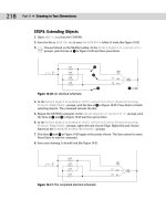
Figure 36-3: Your code should look like this after you place three break points.
If you have difficulty in fixing this bug, you can find the “repaired” version in the Results
folder on the CD-ROM, with the filename list-beautify-without-bug.lsp.
Using the Watch window
The Watch window enables you to examine expressions and variable values as they’re
being evaluated. To watch a variable, select it in the code and choose Debug ➪ Add
Watch, or press Ctrl+W. Visual LISP opens the Watch window listing the expression or vari-
able and displaying its value after an equal sign. If you select an expression or nothing is
selected and you press Ctrl+W, the Add Watch dialog box opens. If it is not already displayed,
enter the expression that you want to watch and click OK. For example, if you add a watch for
(princ (chr 40)), the Watch window displays (PRINC (CHR 40)) = “(“ because (princ
(chr 40)) is another way of telling AutoLISP to print a left parenthesis. After the Watch win-
dow is open, you can add expressions or variables by selecting them and choosing Add
Watch on the Watch window toolbar.
If you have a routine with arguments, you can execute the function with various arguments
and see the results on your watched expressions and variables in the Watch window.
Furthermore, you can add any expression to the Watch window and alter the contents of any
variable while debugging a function.
The file used in the following exercise on using the Watch window, ab36-01.lsp, is in the
Results folder on the CD-ROM.
On the
CD-ROM
On the
CD-ROM
48_788864 ch36.qxp 5/22/06 7:34 PM Page 1129
1131
Chapter 36 ✦ Exploring Advanced AutoLISP Topics
12. To remove the break point, choose View ➪ Breakpoints Window to open the Breakpoints
dialog box. Click Delete All to delete the break point. Visual LISP automatically closes the
dialog box.
13. Click Reset on the Debug toolbar.
14. Close the Watch window and the Visual LISP IDE without saving the file.
As you can see, Visual LISP is not just an editor; it’s a full-featured, integrated development
environment for AutoLISP.
Summary
In this chapter, you examined some of the advanced features of AutoLISP and Visual LISP. You
read about:
✦ Global and local variables
✦ Some of the features of ActiveX
✦ How to use some of Visual LISP’s debugging features, including the Error Trace window,
break points, and the Watch window
In the next chapter, you read about the basics of Visual Basic for Applications, another pro-
gramming language that you can use with AutoCAD.
✦✦✦
48_788864 ch36.qxp 5/22/06 7:34 PM Page 1131
48_788864 ch36.qxp 5/22/06 7:34 PM Page 1132
37
37
CHAPTER
Programming with
Visual Basic for
Applications
V
isual Basic for Applications (VBA) is a programming language
and environment that is included with many Microsoft applica-
tions, such as Word, Excel, PowerPoint, and Access. Since Release 14,
VBA has been available with AutoCAD as well. VBA is ideally suited for
situations in which you need to work with more than one application
at a time. ActiveX, which I discussed in the last chapter in relation
to Visual LISP, enables you to access objects in other applications.
However, you can also use VBA to program AutoCAD alone. This chap-
ter introduces you to VBA and shows how you can start to use this
powerful language to customize AutoCAD.
AutoCAD LT does not support VBA. This entire chapter applies to
AutoCAD only.
Visual Basic for Applications is a variation of Visual Basic. Visual
Basic is not related to any specific application. Visual Basic code is
compiled into an executable file that stands alone, unrelated to any
specific document. VBA, on the other hand, is connected to its appli-
cation and the document in which you created the code. VBA pro-
vides a simple way to customize AutoCAD, automate tasks, and
program applications from within the application.
VBA in AutoCAD works slightly differently from VBA in most other
applications, in that VBA projects are stored in a separate file, with
the DVB filename extension, but can also be stored within the draw-
ing file.
Starting to Work with VBA
After you decide to program AutoCAD, the first step is to select a pro-
gramming language to use.
✦✦✦✦
In This Chapter
Understanding VBA and
AutoCAD
Writing VBA code
Getting user input
Creating dialog boxes
Modifying objects
Creating loops and
conditions
Debugging and
trapping errors
✦✦✦✦
49_788864 ch37.qxp 5/22/06 7:30 PM Page 1133
1134
Part VII ✦ Programming AutoCAD
VBA has the following advantages:
✦ VBA is faster than AutoLISP, even when AutoLISP is compiled.
✦ VBA is common to many other applications. If you’ve used VBA before, you can easily
transfer your knowledge to using VBA in AutoCAD. You’re also more likely to find other
programmers who know VBA compared to AutoLISP.
✦ VBA is generally easier to learn than AutoLISP because of its syntax.
On the other hand, AutoLISP has the advantage of backward compatibility with prior releases
of AutoCAD. Of course, if you’re familiar with AutoLISP but not VBA, it’s hard to beat the ease
of working with a language that you already know and use.
VBA programs are saved in projects. A project contains all of the parts that are needed to exe-
cute the function of the program. You can use the VBA Manager to view your VBA projects.
The VBA Manager also enables you to load, unload, save, and create VBA projects. To open
the VBA Manager, choose Tools ➪ Macro➪ VBA Manager.
Opening the VBA environment
To start working with VBA, you must open the VBA environment. VBA has its own interface,
just like Visual LISP. To open VBA in AutoCAD, choose Tools ➪ Macro➪ Visual Basic Editor
(or type vbaide ↵). Like Visual LISP, VBA has its own interface, called an integrated development
environment, or IDE. AutoCAD displays the VBA environment window.
VBA projects can contain modules. A module is a self-contained piece of programming code.
A VBA project can have one or more modules.
To add a module, choose Insert ➪ Module, or click the drop-down list to the right of the
second button on the VBA IDE Standard toolbar. Then choose Module. AutoCAD opens a
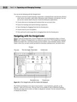
module text editor window so that you can start typing code. In the Project window, VBA adds
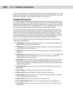
a new module to the list of modules. By default, the first module is called Module1. Figure 37-1
shows the VBA IDE, including the text editor. If you don’t see the Project Explorer or the
Properties window, use the View menu of the VBA IDE to choose Project Explorer or Properties
Window.
You can resize the module text editor as you would any window. As you start adding code to
the text editor, you’ll find it easier to work with a larger window. Click the Maximize button to
enlarge the text editor to its maximum size.
AutoCAD is still running in the background. You can return to it at any time by clicking
its button on the Windows task bar, or by clicking View AutoCAD on the VBA IDE Standard
toolbar.
Getting acquainted with VBA
VBA enables you to easily retrieve, create, and manipulate objects. To get a list of objects,
open the Object Browser by clicking Object Browser on the Standard toolbar or choosing
View➪ Object Browser. Objects are organized into libraries. All of the objects that you work
with in AutoCAD are in the AutoCAD library.
Tip
49_788864 ch37.qxp 5/22/06 7:30 PM Page 1134
1135
Chapter 37 ✦ Programming with Visual Basic for Applications
Figure 37-1: The VBA environment window.
To see the list of AutoCAD objects, click the <All Libraries> drop-down list and choose
AutoCAD. You can see the result in Figure 37-2.
You can resize the panes in the VBA window. Place the mouse cursor on the bar between the
panes until you see the double-headed arrow, and drag it either left or right.
Figure 37-2: You can use the Object Browser to see the
AutoCAD library of objects.
Tip
49_788864 ch37.qxp 5/22/06 7:30 PM Page 1135
1136
Part VII ✦ Programming AutoCAD
Objects and collections of objects
In the left pane, labeled Classes, you see the list of objects. In VBA, you can have both individ-
ual objects and collections of objects. For example, AcadLayer would be the layer object, and
AcadLayers would be the collection of layers. The purpose of collections is to enable you to
work with a group of objects. For example, to add a layer, you add it to the collection of lay-
ers; this is because the new layer is not related to any existing layer.
Methods and properties
What can you do with objects in VBA? First, objects can have properties. For example, you
can set an ellipse to the color red because one of the properties of the ellipse object is
TrueColor. (Of course, all drawing objects have TrueColor as one of their properties.)
Second, objects have methods. A method is an action that you can take on the object. For
example, you can delete (erase) an ellipse because Delete is a method of the ellipse object
(as well as of all drawing objects).
In the Object Browser, the right pane, Members, lists the properties and methods of any
object that you choose in the Classes pane.
Investigating the hierarchy model
Although you might first think that an object in VBA is the same as an object in an AutoCAD
drawing, there is more to the story. In VBA, everything is an object. For example, AutoCAD as
an application is an object. Your current drawing is also an object. Model space and paper
space are also objects. Therefore, to specify an object in your drawing, you need to specify
the application, the drawing, and finally the object in the drawing. To do this, VBA works with
a hierarchy of objects. For example, the hierarchy makes it possible to distinguish between
an object in your drawing and an object in an Excel spreadsheet.
Objects are specified from the most general to the most specific, with a period between each
part of the definition. You then add the desired method or properties after another period.
For example, you can use the following VBA code to add a circle:
Application.ActiveDocument.ModelSpace.AddCircle(center, radius)
A shortcut for Application.ActiveDocument is ThisDrawing, and so you can also use:
ThisDrawing.ModelSpace.AddCircle(center, radius)
In order to work with any object, you need to know where it fits in the hierarchy.
The quickest way to see the hierarchical structure from the VBA IDE is to choose
any method or property in the Object Browser and to choose Help on the Object Browser’s
toolbar. On the Contents tab, choose Object Model to see the listing in Figure 37-3.
Within AutoCAD, choose Help ➪ Additional Resources ➪ Developer Help. You’re now in a
new Help system. On the Contents tab, double-click ActiveX and VBA Reference. Click Object
Model to see the hierarchical model shown in Figure 37-3, or double-click Objects to see the
alphabetical object list.
Note
49_788864 ch37.qxp 5/22/06 7:30 PM Page 1136
1137
Chapter 37 ✦ Programming with Visual Basic for Applications
Figure 37-3: The object model shows you the hierarchy of all of
the VBA objects so that you can work with them.
STEPS: Becoming Acquainted with the VBA Environment
1. With any drawing open in AutoCAD, choose Tools➪ Macro ➪ Visual Basic Editor.
AutoCAD opens the VBA IDE.
2. Choose Insert ➪ Module from the menu. The VBA IDE opens the module text editor
window.
3. Move down to the Windows task bar and click the AutoCAD button to return to
AutoCAD. Now click the Microsoft Visual Basic button to return to the VBA IDE.
4. Click Object Browser on the VBA IDE Standard toolbar. Click the <All Libraries>
drop-down list and choose AutoCAD. If necessary, maximize the window by click-
ing the Maximize button at the top-right corner of the window.
5. In the Classes pane, click AcadLine. You see the associated properties and methods in
the right pane.
6. In the right pane, which is labeled Members of AcadLine, click Delete. You see the fol-
lowing at the bottom of the window:
Sub Delete()
Member of AutoCAD.AcadLine
Deletes a specified object
49_788864 ch37.qxp 5/22/06 7:30 PM Page 1137
1138
Part VII ✦ Programming AutoCAD
Sub indicates the start of a VBA subroutine. Methods are listed in this way.
7. In the right pane, click Layer. At the bottom of the window, you see the following:
Property Layer As String
Member of AutoCAD.AcadLine
Specifies the current layer of the object
This indicates that Layer is a property of AcadLine. String refers to the data type, dis-
cussed later in this chapter.
8. Click Help in the Object Browser window. You see the Help page for the Layer
property.
9. On the Contents tab, double-click Objects and then click Line object. Scroll down to see
all of the properties and methods that belong to the Line object.
10. In the second paragraph of the description, the word AddLine is underlined with a
hypertext line. Click it to see the description of the
AddLine method.
11. At the top of the page, click Example (also with a hypertext underline). You see an
example of VBA code for creating a line.
12. Close Help by clicking the Close button at the top-right corner of each window.
Leave the VBA IDE window open if you’re continuing on to the next exercise.
Accessing help
VBA offers several help features. You’ve already seen the Object Browser, which provides you
with a list of objects as well as their properties and methods. To access help on an object,
choose it in Object Browser and click Help. You can do the same for a method or property,
as shown in Figure 37-4.
After you open a help page, click Example to see an example. These examples are a great way
to learn VBA. You can copy a snippet of VBA code and paste it into your own routine, and
then edit it as you want.
For more general help, AutoCAD offers two systems:
✦ The ActiveX and VBA Reference is an alphabetical listing of objects, methods, proper-
ties, and events.
✦ The ActiveX and VBA Developer’s Guide explains ActiveX automation concepts and
techniques.
To access these reference guides, switch to AutoCAD and choose Help ➪ Additional
Resources➪ Developer Help.
The Microsoft Visual Basic for Applications Help provides information on the general VBA
environment. Click Help on the VBA IDE Menu Bar toolbar, or choose Help ➪ Microsoft
Visual Basic Help. Here you see help for other VBA-enabled applications that you may
have. You can use this when you’re ready to write VBA code that integrates more than one
application.
49_788864 ch37.qxp 5/22/06 7:30 PM Page 1138
1139
Chapter 37 ✦ Programming with Visual Basic for Applications
Figure 37-4: The help page for the Center Property.
After you start programming, you can get help on any expression by clicking it and
pressing F1. For example, you can type AddLine and press F1 to access help on how to
create a line.
Writing VBA Code
Now that you’re familiar with the structure of VBA objects, methods, and properties, you’re
ready to start writing some code. As with any programming language, you need to learn syn-
tax and understand variables and when to use them. Luckily, AutoCAD’s VBA Help includes
many examples to guide you along the way. After you write some code, you can use it in
AutoCAD.
Table 37-1 lists the various components of VBA code. This table defines various terms that
you can often use when working with VBA.
49_788864 ch37.qxp 5/22/06 7:30 PM Page 1139
1140
Part VII ✦ Programming AutoCAD
Table 37-1: Components of VBA Code
Term Definition
Procedure Code that does something and has a name. A procedure can be a subroutine, a
function, or a property.
Project A set of forms and modules.
Module A set of subroutines, functions, and declarations that are usually related and comprise
a distinct component in a project. A module can contain zero (0) or more procedures
(subroutines and functions).
Form A container for the visual components, such as buttons and text boxes, of a dialog box
that you create for your VBA project.
Subroutine A procedure, written in VBA code, that does not return a value.
Function A procedure, written in VBA code, that returns a value.
Property A procedure, written in VBA code, that specifies a value (the property of an object).
Declaration One or more nonexecutable statements that name constants or variables and define
their attributes (such as data type).
Macro A public subroutine that a user can directly execute.
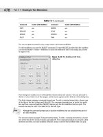
When you start to create code, VBA can create the basic structure for each procedure for
you. With a text or code window displayed, choose Insert ➪ Procedure to open the Add
Procedure dialog box shown in Figure 37-5.
In the Name text box, type in a name for the new procedure, and then choose the type of
procedure that you want to create. Choose whether you want the scope to be Public or
Private and then click OK. If a subroutine (called sub for short) is declared Public, it is visible
(can be called) from other modules or from the AutoCAD Macros dialog box. A sub that is
declared Private is visible only within that module.
Figure 37-5: The Add Procedure dialog box.
49_788864 ch37.qxp 5/22/06 7:30 PM Page 1140
1141
Chapter 37 ✦ Programming with Visual Basic for Applications
If you check the All Local Variables as Statics check box in the Add Procedure dialog box, your
variables retain their values between the times that they’re used.
Looking at VBA syntax
To start programming, you need an idea of how a VBA routine is put together. Here is a com-
plete VBA routine that draws a 3D box.
‘Insert a 3D Solid Box
Sub Box()
‘declare input variables to AddBox()
Dim dOrigin(0 To 2) As Double ‘origin is array of doubles ‘(x,y,z)
Dim dLength As Double ‘length
Dim dWidth As Double ‘width
Dim dHeight As Double ‘height
Dim myBox As Acad3DSolid ‘holds return from AddBox()
dOrigin(0) = 0# ‘set origin to (0,0,0)
dOrigin(1) = 0#
dOrigin(2) = 0#
dLength = 5# ‘make a cube 5 by 5 by 5
dWidth = 5#
dHeight = 5#
‘create the box in modelspace of the current drawing
Set myBox = ThisDrawing.ModelSpace.AddBox(dOrigin, dLength, dWidth,
dHeight)
‘change the viewpoint to better see the box
ThisDrawing.SendCommand (“VPOINT 1,1,1 “)
End Sub
Here’s what the code means:
✦ Line 1: Any text starting with an apostrophe (
‘) is a comment. Placing comments in
your routines helps you and others to understand what you’re doing.
✦ Line 2:
Sub indicates the start of a procedure, which is a named, unified piece of code.
You can have several subroutines in a VBA project. A project is the file that you save,
and it has a DVB filename extension. Each project contains the components of your
subroutines, dialog boxes, and so on. The next word is the name of the subroutine.
Within the parentheses, you can add arguments, if any. Use an empty set of parenthe-
ses if there are no arguments. Declaring variables is discussed later in this chapter.
✦ Line 3: Another comment describing the next few lines of code. It’s always a good idea
to comment your code, indicate what is happening, and even write notes to yourself to
remind you of your intent.
✦ Line 4: You can also declare variables using the
Dim statement. Here dOrigin is used
as the variable for the center of the box.
(0 To 2) means that the origin will have three
parts to it, for the X, Y, and Z coordinates.
Double is a type of variable that is suitable
for most coordinates. More about variable types later.
Note
49_788864 ch37.qxp 5/22/06 7:30 PM Page 1141
1142
Part VII ✦ Programming AutoCAD
✦ Lines 5–7: Here you declare the dLength, dWidth, and dHeight variables, which will be
used as the length, width, and height of the box. These are declared as type
Double,
which is also indicated by the
d prefix on the variable names. This isn’t required, but
it’s a good idea to use a naming scheme for variables to help remind you of their type,
especially as you get deeper into programming or have to come back to some code
after not seeing it for a while.
✦ Line 8: Here you declare a variable called
myBox as an Acad3DSolid to refer to the new
box that will be created.
Acad3DSolid is a data type that is specific to AutoCAD, and
suitable for (you guessed it) referencing a 3D solid in your drawing. You can find other
AutoCAD data types by looking in the Object Browser, or by looking at the Object Model
as I explained earlier in this chapter.
✦ Lines 9–11: Here you specify the X, Y, and Z coordinates of the origin of the box.
The values are assigned to the
dOrigin variable. The pound sign (#) is used to
indicate a double-precision floating-point value. Use of the
# sign is not required here
but is more accurate and more clearly indicates your intentions. In some situations,
rounding errors can occur when assigning numbers of one type to variables of another
type, such as when you assign integers to doubles and doubles to integers.
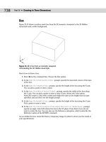
✦ Lines 12–14: Set the length, width, and height of the box to 5.
✦ Line 15: Another comment.
✦ Line 16: Finally, you’re ready to actually do something. The
Set statement is used to
set a variable to an object. Here you set the variable
myBox to an Acad3DSolid defined
by
AddBox(dOrigin, dLength, dWidth, dHeight). The AddBox method creates a new
3D box. You need to define its origin, length, width, and height by using the variables
that you’ve previously defined. The
AddBox method is a member of ModelSpace, which
is a member of
ThisDrawing. You use ThisDrawing in VBA to access the current draw-
ing. Because VBA within AutoCAD is automatically connected to AutoCAD, you don’t
need to specify the application (that is, AutoCAD).
✦ Line 17: Not another comment! Ask yourself these questions: If I looked at this code
without the comments, would I have a harder time understanding it? What if there is
a bug and I ask another programmer to find it? What if I am that programmer?
✦ Line 18: Here we send the VPOINT command to change the viewpoint. Otherwise, the
box that we just created will simply look like a square viewed from the top. The space
after the numbers 1,1,1 and before the quotation mark is important; it signifies the end
of the command. It’s like pressing the Enter key for this command.
✦ Line 19:
End Sub ends the subroutine.
To find the syntax for a statement that you want to use, look in VBA Help, as explained in the
“Accessing help” section earlier in this chapter. In the preceding VBA routine, you might want
to click AddBox and press F1 to find the syntax and elements that are required for creating a
box. Then click Example to see an actual example of code for that statement.
Saving a VBA routine
As I mention earlier, the AutoCAD version of VBA saves VBA projects as separate files with
a DVB file name extension. However, when you run a routine, AutoCAD lists it in the format
ModuleName:Procedure Name. If your project has only one module, you can give the module
and the procedure the same name. However, most VBA routines have more than one module,
with one module controlling the rest. By running the controlling module, you run the whole
project.
49_788864 ch37.qxp 5/22/06 7:30 PM Page 1142
1143
Chapter 37 ✦ Programming with Visual Basic for Applications
To name a module, look in the Properties window. After you’ve created a module, the VBA IDE
lists its name property as Module1 by default. Double-click Module1 and type a new name.
Notice that the module name in the Project window also changes accordingly.
A module name (as well as the names of other forms and controls) must start with a letter
and can be up to 31 characters. Only letters, numbers, and the underscore character are
allowed.
To save a project as a separate file, which includes all of the modules, click Save on the
VBA IDE Standard toolbar. VBA returns you to AutoCAD and opens the Save As dialog
box. Type a name for your project, choose a location, and click Save.
You can save your project in the
Sample\VBA subfolder in the AutoCAD 2007 folder, or use
another folder that is in AutoCAD’s support file search path.
Loading a VBA routine
Before you run a VBA routine, it must be loaded. If you’re working on the routine and want to
run it to check how it works — which you’ll do often — you don’t need to load the routine.
However, if you want to run a routine that hasn’t been loaded, you need to use the VBALOAD
command. When you choose Tools ➪ Macro➪ Load Project (or type vbaload ↵), AutoCAD
opens the Open VBA Project dialog box. Navigate to your project, choose it, and click Open.
(AutoCAD asks you to confirm that you want to enable macros.) The project is now loaded.
Running a VBA routine
After you complete a subroutine, you can run it in AutoCAD. After all, that’s the reason for
writing VBA code in the first place. To run a VBA routine, choose Tools ➪ Macro ➪ Macros
(or type vbarun ↵). In the Macros dialog box, choose the module that you want to run and
click Run. AutoCAD runs the module, including other modules that may be controlled by the
module that you run.
Using the Visual Basic Editor
When you type code from scratch in the Visual Basic Editor, you immediately notice that
Visual Basic color-codes your text as you go. The most common colors are:
Normal text Black
Syntax-error text Red
Comments Green
Keyword text Blue
Keywords include variable types and other words that Visual Basic recognizes, such as
Dim
and Sub.
You can customize these colors by choosing Tools➪ Options from the Visual Basic menu and
then choosing the Editor Format tab. Choose a type of text and then choose the desired color.
Click OK.
Tip
Note
49_788864 ch37.qxp 5/22/06 7:30 PM Page 1143
1144
Part VII ✦ Programming AutoCAD
When you start to type a keyword that Visual Basic recognizes, you’ll often see a box pop up
that enables you to choose from a list, or that helps you to complete the word. The editor
also adds or removes spaces, and capitalizes certain words for you to improve your syntax.
If you make a syntax mistake, a small error message often appears as you work. In these
ways, the Visual Basic Editor helps you to type accurate code.
STEPS: Creating, Saving, and Running a VBA Program
1. Open a new drawing using the acad.dwt template. Choose Tools ➪ Macro➪
Visual Basic Editor.
2. Choose Insert ➪ Module. VBA opens the module text editor. (If you’ve previously
opened a module, Visual Basic may launch with a blank module already open. In that
case, skip this step.)
3. Choose Insert ➪ Procedure. In the Name text box, type DrawTorus. The type should be
Sub and the scope should be Public. Click OK.
4. Type the following code. (Note that the second and last lines are already there for you.)
‘insert a Torus
Public Sub DrawTorus()
‘declare variables
Dim dCenter(0 To 2) As Double
Dim dRadius1 As Double
Dim dRadius2 As Double
Dim myTorus As Acad3DSolid
‘set center of torus to 0,0,0
dCenter(0) = 0#
dCenter(1) = 0#
dCenter(2) = 0#
dRadius1 = 10# ‘torus radius
dRadius2 = 2# ‘tube radius
‘insert the torus
Set myTorus = ThisDrawing.ModelSpace.AddTorus(dCenter, dRadius1,
dRadius2)
‘set the viewpoint and shade it
ThisDrawing.SendCommand (“VPOINT 1,1,1 VSCURRENT CONCEPTUAL “)
End Sub
5. In the Properties window, change the name of the module to DrawTorus.
6. Because this routine is active, you don’t need to load it. Choose Save on the VBA IDE
Standard toolbar. Save the project as
ab37-01.dvb in your AutoCAD Bible folder.
7. Use the Windows task bar to return to your drawing. Choose Tools ➪ Macro ➪ Macros.
In the Macros dialog box, choose DrawTorus and click Run. VBA draws and shades the
torus.
Don’t save your drawing.
49_788864 ch37.qxp 5/22/06 7:30 PM Page 1144
1145
Chapter 37 ✦ Programming with Visual Basic for Applications
Here’s an explanation of the routine that you just wrote and used. Note that blank lines are
ignored.
✦ Line 1: Comment describing routine.
✦ Line 2: This is a public subroutine named DrawTorus with no parameters.
✦ Line 3: Comment indicating which variable declarations are next.
✦ Line 4: Declare the array to hold the X, Y, and Z coordinates for the center of the torus.
✦ Line 5: Declare the variable to hold the radius of the torus.
✦ Line 6: Declare the variable to hold the radius of the tube.
✦ Line 7: Declare the variable to hold the created 3D object.
✦ Line 8: Comment.
✦ Lines 9–11: Set the center to 0,0,0.
✦ Line 12: Set the torus radius to 10.0.
✦ Line 13: Set the tube radius to 2.0.
✦ Line 14: Comment.
✦ Line 15: Create the torus.
✦ Line 16: Comment.
✦ Line 17: Send commands to AutoCAD to set the viewpoint and set the visual style to
Conceptual for better viewing.
✦ Line 18: End of subroutine.
Understanding variables
A variable holds a value for later use in your program. In VBA, you don’t need to explicitly
declare your variables in advance (as long as you don’t include Option Explicit, which I
explain later). You use the
Set statement to set a variable to an object, as in the example
here. This statement creates a variable,
cir, and sets its value equal to the circle that the
AddCircle method creates.
Set cir = ThisDrawing.ModelSpace.AddCircle(cen, radius)
When you create a variable in this way, VBA assigns the default variant type to it. The variant
type of variable can contain numbers, dates, or strings (of text).
However, declaring variables explicitly in advance has two advantages:
✦ You can specify the type of variable, which usually uses less memory than the default
variant type.
✦ As you continue to enter code, VBA checks the variable’s spelling for you, thus reduc-
ing the chance for errors.
You declare variables using the
Dim statement. Here’s an example:
Dim radius As Double
49_788864 ch37.qxp 5/22/06 7:30 PM Page 1145
1146
Part VII ✦ Programming AutoCAD
You can create three different levels of variables:
✦ A
Public variable is available to all procedures in the project. It is shown as follows:
Public dRadius As Double
✦ A module-level variable is available to all of the procedures in the module. You create a
module-level variable by placing the declaration (with the
Dim statement) at the top of
a module, in a Declarations section. Another way to create a module-level variable is to
use the
Private statement. Examples are shown here:
Dim dNum3 as Double
Private dNum2 as Double
✦ A procedure-level variable is used only within a procedure. You can place the variable
anywhere within the procedure, as long as you declare the variable before you use it.
Placing the statement
Option Explicit in a Declarations section requires all variables to be
declared. Using Option Explicit is a way to force yourself to write your code more carefully.
Declared variables are easier to debug because they’re easier to find.
Table 37-2 describes the kinds of variables that you can declare.
Table 37-2: VBA Variable Types
Variable Description
Boolean For variables that can have only two values — True or False.
Byte Positive integers from 0 to 255.
Integer Integers from –32,768 to +32,767.
Long Integers from –2,147,483,648 to +2,147,483,647.
Currency Values from –922,337,203,685,477.5808 to +922,337,203,685,477.5807. Use this variable
for currency or for other values that need accuracy to several decimals.
Single Single-precision floating-point values. Single variables use less memory than double
variables, but their values are limited.
Double Double-precision floating-point values. Double variables offer much greater precision
than single variables. Most coordinates use this variable type. Three double variables
create the X, Y, and Z values.
Date Holds dates and times that are stored as real numbers. The number to the left of the
decimal is the date, and the number to the right of the decimal is the time.
String Fixed- or variable-length text strings, including letters, numbers, spaces, and punctuation
characters.
Object Objects such as an application, a drawing, or a drawing object.
Variant Contains numbers, dates, or strings. When you don’t declare a type for a variable, VBA
uses this type by default.
49_788864 ch37.qxp 5/22/06 7:30 PM Page 1146
1147
Chapter 37 ✦ Programming with Visual Basic for Applications
Here’s an example that uses the Date variable type and displays it in a message box:
Sub DateDemo()
Dim dt As Date
Dim dbl As Double
dt = Now ‘set the dt to the current date and time
dbl = dt ‘assign this date value to a double
MsgBox “Normal date version: “ & dt & “ Double version: “ & dbl
End Sub
Running DateDemo (by pressing F5) would show something similar to:
Normal date version: 5/10/2005 8:03:13 PM
Double version: 38482.8355671296
Creating VBA statements
Although a complete discussion of how to write VBA code is beyond the scope of this book,
some general principles will be helpful.
A statement in VBA is the most basic unit of code. It contains a complete instruction. There
are three kinds of statements:
✦ A declaration names a variable, constant, or procedure, as in this example:
Dim dOrigin as Double
✦ An assignment assigns a value to a variable or constant. For example:
dOrigin = 0#
✦ An executable creates an action. For example, it can execute a method or function, or
create a loop or branch that acts on a block of code, as shown here:
Set myBox = ThisDrawing.ModelSpace.AddBox(dOrigin, dLength, dWidth,
dHeight)
VBA has many keywords, functions, and other components that you can use to create code.
To find the basic components of the VBA language, choose Help ➪ Microsoft Visual Basic
Help. From the Contents tab, double-click Visual Basic Language Reference, which lists terms
that are part and parcel of VBA. Here are some examples:
✦ Constants: Constants can be used anywhere in your code to provide a named value.
For example, VBA offers color and date constants that you can use to specify colors
and dates.
✦ Functions: VBA includes many functions that you’ll find familiar if you’ve used AutoLISP.
For example, the
ABS function returns the absolute value (without a plus or minus sign)
of any number. The
DATE function returns the current system date.
✦ Keywords: Keywords are words that have a special meaning in VBA. They are often
used as parts of VBA statements. For example,
Else is a keyword that is used in the
If Then Else statement. You’re already familiar with the Set keyword, which is
used in the
Set statement.
49_788864 ch37.qxp 5/22/06 7:30 PM Page 1147
1148
Part VII ✦ Programming AutoCAD
✦ Operators: VBA includes all of the usual arithmetic operations, such as +, –, *, /, and ^.
You can also use
& to concatenate text strings. There are several logical operators,
such as
and, not, and or.
✦ Statements: Statements help you to create the flow of your code. You’re already familiar
with the
Set statement. Other statements are For Each Next and If Then Else.
These provide looping capabilities in VBA.
Remember that you can also find a list of objects and their properties and methods in the
Object Browser, as I explained earlier in this chapter.
Getting User Input
The examples shown in this chapter weren’t very useful, partly because the routines pro-
vided no way to get user input for the properties of the objects that they drew. There are two
main ways to get user input: on the command line and through a dialog box. In this section,
I explain how to get user input on the command line.
In order to use the user-input methods, you need to first use something called the Utility
object. The Utility object belongs to the Document object, and controls the methods that
get user input. You can also use ThisDrawing, as in the following example.
Dim iReturn as Integer
iReturn = ThisDrawing.Utility.GetInteger(“Enter an integer: “)
Here you set a variable called iReturn that is equal to the integer that the user types on the
command line. The prompt is
Enter an integer:.
You can use this type of user input to get a pick point, a numeric value (such as the radius of
a circle), a text string, or an object. Use this method when the input is short and sweet.
To avoid several prompts appearing on the same line, use
vbCrLf, the carriage return/linefeed
constant, at the beginning of a prompt, as in the following example:
prompt1 = vbCrLf & “Specify center point: “
Here’s an example that illustrates how to get user input on the command line:
Sub AddCircle()
Dim thePt As Variant
Dim theRadius As Double
Dim myCircle As AcadCircle
thePt = ThisDrawing.Utility.GetPoint(, vbCrLf & “Enter Center
Point:”)
theRadius = ThisDrawing.Utility.GetReal(“Enter radius: “)
Set myCircle = ThisDrawing.ModelSpace.AddCircle(thePt, theRadius)
End Sub
49_788864 ch37.qxp 5/22/06 7:30 PM Page 1148
1149
Chapter 37 ✦ Programming with Visual Basic for Applications
Table 37-3 lists some commonly used methods for getting user input. If you know the GET
functions in AutoLISP, you’ll be familiar with these methods.
Table 37-3: Common User-Input Methods
Method Syntax Description
GetEntity GetEntity Object, The user selects an object (entity) by picking it. Returns the object
PickedPoint, Prompt in the first parameter and the point picked in the second parameter.
The prompt is optional. Example: ThisDrawing.Utility.
GetEntity getObj, basePnt, “Select an object” where
getObj has been declared as an Object type variable.
GetInteger RetVal = GetInteger Any integer from –32,768 to +32,767 is valid. The prompt is
(Prompt) optional. Example: getInt = ThisDrawing.Utility.
GetInteger(“Enter an integer: “)
GetPoint RetVal = GetPoint Returns a variant (which contains a three-element array of doubles).
(Point, Prompt) The user can pick a point, or type in a coordinate. If the Point
parameter (optional) is provided, AutoCAD draws a rubber band
line from Point to the current crosshair position. The prompt is also
optional. Example: getPnt = ThisDrawing. Utility.GetPoint
(, “Specify a point: “)
GetReal RetVal = GetReal Gets any real (positive or negative) number. The prompt is optional.
(Prompt) Example: getaReal = ThisDrawing.Utility.GetReal
(“Enter a real number: “)
GetString RetVal = GetString The HasSpaces parameter specifies whether the string can contain
(HasSpaces, Prompt) spaces. If the HasSpaces parameter is TRUE, the string can
contain blanks and the user must press Enter to end input. If
HasSpaces is FALSE, either entering a blank or pressing Enter
ends input. The prompt is optional. Example: getaString =
ThisDrawing.Utility.GetString(False, “Enter text
(a space or <enter> terminates input):”)
STEPS: Creating a VBA Routine That Gets User Input
1. Open a new AutoCAD drawing using the acad.dwt template.
2. To start a new project, choose Tools➪ Macro ➪ VBA Manager. Click New and then click
Visual Basic Editor.
3. Choose Insert ➪ Module and then choose Insert ➪ Procedure. Name it HappyFace and
click OK.
49_788864 ch37.qxp 5/22/06 7:30 PM Page 1149
1150
Part VII ✦ Programming AutoCAD
4. At the cursor, type the following:
Dim prompt As String, prompt2 As String
Dim cen As Variant
Dim rad As Double
Dim cir As AcadCircle
Dim arc As AcadArc
Dim pi As Double
Dim dStart As Double ‘start angle
Dim dEnd As Double ‘end angle
pi = 3.1415
prompt = vbCrLf & “Specify center point: “
prompt2 = vbCrLf & “Specify radius: “
‘get center point from user
cen = ThisDrawing.Utility.GetPoint(, prompt)
rad = ThisDrawing.Utility.GetDistance(cen, prompt2)
‘draw head
Set cir = ThisDrawing.ModelSpace.AddCircle(cen, rad)
‘draw smile
dStart = 225 * pi / 180 ‘pi / 180 converts to radians
DEnd = 315 * pi / 180
Set arc = ThisDrawing.ModelSpace.AddArc(cen, rad / 2, dStart, dEnd)
‘draw eyes
cen(0) = cen(0) - rad / 4
cen(1) = cen(1) + rad / 4
Set cir = ThisDrawing.ModelSpace.AddCircle(cen, rad / 8)
cen(0) = cen(0) + rad / 2
Set cir = ThisDrawing.ModelSpace.AddCircle(cen, rad / 8)
5. Change the module name to HappyFace.
6. Choose Save from the VBA IDE Standard toolbar, and save the VBA project as
ab37-02.dvb in your AutoCAD Bible folder.
7. Return to your drawing and choose Tools ➪ Macro➪ Macros. In the Macros dialog box,
choose HappyFace and click Run.
8. Respond to the prompts. HappyFace draws the circle with the center point and radius
that you specify.
You don’t need to save your drawing.
The previous example uses
GetDistance rather than GetReal to enable the user to select
the radius of the circle with the mouse. The center point that you previously selected feeds
into the
GetDistance function. Also, there are calculations to convert degrees to radians.
The location and size of the eyes and smile are relative to the center and radius.
49_788864 ch37.qxp 5/22/06 7:30 PM Page 1150
1152
Part VII ✦ Programming AutoCAD
Understanding the Toolbox toolbar
The Toolbox toolbar contains the tools that you need to create a dialog box. These are the
familiar controls that you see in the dialog boxes that you use all the time, such as text boxes,
list boxes, check boxes, and so on.
Table 37-4 explains the Toolbox toolbar buttons.
Table 37-4: The Toolbox Toolbar Buttons
Button Description
Select Objects Enables the user to select objects
Label Creates a label on the dialog box
TextBox Enables the user to type in text
ComboBox Combines features of text and list boxes
ListBox Enables the user to choose from a list
CheckBox Creates a box that can be checked or unchecked
OptionButton Enables the user to choose one option from several possibilities (also called a
radio button)
ToggleButton Creates an on/off switch
Frame Creates a box around a section of the dialog box
CommandButton Creates a button that executes a command, such as OK and Cancel buttons
TabStrip Creates tabs along the top of the dialog box
MultiPage Creates multiple pages
ScrollBar Creates a scroll bar
SpinButton Enables the user to specify a number
Image Inserts an image
If you think that the Toolbox toolbar has a lot of possibilities, right-click the Toolbox toolbar
and choose Additional Controls. From the Additional Controls dialog box, you can choose
from many more controls.
Changing dialog-box properties
After you insert a user form, you should name it. Find the Name property in the Properties
window, and change it from UserForm1 (the default name) to any useful name that you want.
You might find it useful to use the word frm in the name. For example, for a routine to draw a
circle, you could call the user form
frmCircle.
Tip
49_788864 ch37.qxp 5/22/06 7:30 PM Page 1152