Mastering Autodesk 3ds Max Design 2011 phần 8 ppsx
Bạn đang xem bản rút gọn của tài liệu. Xem và tải ngay bản đầy đủ của tài liệu tại đây (2.91 MB, 97 trang )
654
|
CHAPTER 13 CreatInG anIMatIons
Notice your rendering time. Here it’s blindingly fast, about one second a frame. If you have a
much slower render time, go take a quick break.
Once the animation is created, you can view the rendered animation from within 3ds Max
by using the View Image File command or by locating the AVI file using Windows Explorer and
double-clicking it. Unlike the Preview, the player doesn’t automatically launch when the render-
ing is complete.
1. Choose Rendering View Image File. The View File dialog box displays.
2. Locate and select Myfirstanimation.avi, and then click Open. Windows Media Player
opens and plays back the animation. If you have another application set to play back AVI
files, that application will open and play the AVI file.
As you can see, the animation is short and still pretty crude, but at least you can tell whether
the lights are doing what you want them to do.
Creating a Quick Overall Study Animation
Now suppose you want to get a quick view of the overall animation to make sure everything is
working as planned. In the next exercise, you’ll adjust some of the frame output settings to limit
the number of frames that are animated. This will help reduce the total animation time so that
you’ll see the results quickly. You’ll use a different file format that offers a bit more control at file
creation.
1. Make sure the Common tab is selected in the Render Setup dialog box, and then click the
Active Time Segment radio button in the Time Output group.
2. In the Every Nth Frame input box, enter 3. This will cause the renderer to create an
animation that renders only every third frame. Consequently, the animation will take
approximately one-third of the time to render all the assigned frames.
3. Click the Files button in the Render Output group; then, in the Render Output File dialog
box, enter Mysecondanimation for the filename.
4. Select MOV QuickTime File (*.mov) in the Save As Type drop-down list and click Save.
As you’ll see in a moment, the QuickTime file format lets you set the playback frame rate.
Quicktime output will not be available on 64-bit operating systems with 3ds Max 64 bit
installed. If Quicktime is not available, use the AVI format again with MJPEG compres-
sion. The animation will play back in just over 6 seconds instead of 20.
Figure 13.3
The AVI File Com-
pression Setup
dialog box
renderInG the anIMatIon
|
655
5. In the Compression Settings dialog box, change the Frames per Second setting to 10. Note
that you can set the Quality slider and also select the color depth for the MOV file. The
lower the Quality setting, the smaller the file size will be. Decreasing color depth can also
reduce file size. Click OK to close the Compression Settings dialog box and return to the
Render Setup dialog box.
Changing the File Saving Parameters
After rendering a scene to a particular still image or animated file format, the dialog boxes used
to set the file’s parameters (compression, frame rate, and so on) no longer appear. To change the
file’s parameters without changing the file’s type, click the Setup button in the Render File Output
dialog box.
6. Click the Render button in the Render Setup dialog box. This time the rendering will take
a good deal more time because you will be rendering about 200 frames overall (one-third
of 600 frames). Check the Time Remaining field in the Common Parameters rollout to see
an estimate of the remaining rendering time.
7. Use the View File dialog box (Rendering View Image File) to play back the animation
when it finishes rendering.
Lowering the Frames per Second
Rendering at 10 frames per second (fps) is near the limit of flicker fusion, where you start to perceive
individual frames rather than the illusion of continuous motion. The animation will be a bit jerky
but will still be a valuable sample and allow you to get a sense of timing in the segment without
rendering every frame.
This animation is still crude, and you may detect that it is not quite as smooth in the playback
as the previous animation, but it gives you a far better idea of how the final rendering will look
than did the preview animations you used in the previous chapter, because it includes rendered
light and shadow. The test animations that you render may also show you problems that need
fixing. This is exactly the kind of feedback you want from tests before you commit all the time
required to render the entire animation.
Adding a Moving Car
Your animation work so far has involved moving a camera around the villa. Of course, you can
animate other objects in your model. Let’s add a car to the villa animation to see how to con-
trol the behavior of objects other than cameras. By animating a car, you’ll explore how you can
rotate an object through time. You’ll use a simple car model to see how you can make an object
move smoothly in an animation.
656
|
CHAPTER 13 CreatInG anIMatIons
First, insert a Container that has the car model inside it.
1. Right-click the Top viewport; then click the Maximize Viewport Toggle to enlarge the view.
2. Select the skydome object.
3. Right-click; then, in the quad menu, click Hide Selection.
4. Click the Application button, and choose References Inherit Container, as shown in
Figure 13.4
5. In the Inherit Container dialog box, select the LowResCar_Container01.maxc file.
3ds Max Container Files
3ds Max uses the extension *.maxc to identify models that have been prepared as Container files.
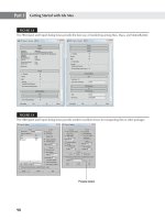
The car appears in the scene near the lower-right corner of the villa, just out of view of the
Camera.View.3DFRONT at frame 0.
Now that you have the car in the scene, it’s time to animate it. Just as with the camera, you’ll
need to enter Auto Key mode, select a time with the Time slider, and then move the car.
1. With the Container01 object still selected, use the Absolute Mode Transform type-in field
and move the car to X = 15’ and Y = 150’.
2. Click the Auto Key button at the bottom of the interface.
3. Move the Time slider to frame 200.
4. Click the Select by Name tool. On the Select from Scene dialog box, select the Display
Containers toggle to make the container appears in the list.
5. Select the Container01 object from the list, and click OK.
Figure 13.4
Adding the
Container repre-
senting the car
renderInG the anIMatIon
|
657
Click the Selection Lock Toggle so you don’t have to worry about accidentally deselecting
the car’s Container while you are animating it.
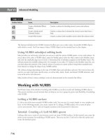
Click the Select and Move tool, and then move the car to the position shown in
Figure 13.5.
To help you visualize the path of the car, turn on its trajectory:
1. Right-click in the viewport and select Object Properties.
2. In the Display Properties section of the Object Properties dialog box, click By Layer to
change the display properties of the car to By Object.
3. Click the Trajectory check box and click OK.
Now you’ve got a visible trajectory. Let’s adjust the beginning and ending keyframes so the
car starts and stops smoothly on its path:
1. Click the Motion tab in the Command panel.
2. In the Key Info (Basic) rollout, click and drag the In flyout and select Slow.
3. Click the left-facing arrow in the upper-left corner of the Key Info (Basic) flyout to go to
keyframe 1.
4. Select the Slow tangent option for the Out parameter.
5. Move the Time slider from frame 0 to frame 200 and watch what the car does.
You can see that the car moves in a straight line between the two keyframes. The orientation
of the car has not changed, so the car looks like it is moving slightly sideways. Finally, the car is
driving near a tree.
Next, you’ll modify the trajectory of the car so that it gives the tree a wider berth. You’ll also
add some rotation to the car so that it looks like it’s turning into the building.
1. Move the Time slider to frame 120. This is where you’ll add another keyframe in order to
move the trajectory away from the tree.
2. With the Select and Move tool still active, move the car to the location shown in
Figure 13.6.
Figure 13.5
Move the car to the
new location at
frame 200.
658
|
CHAPTER 13 CreatInG anIMatIons
3. Click the Select and Rotate tool, and rotate the car so that it is aligned with the trajectory
at this keyframe. By rotating the car at this point, you are adding a rotation key.
4. Now click and drag the Time slider between frames 0 and 200 to see the motion of the car.
The car moves around the tree and turns, although the turning is not well coordinated with
the trajectory. The car also does not complete its turn at frame 200, where it comes to rest. You
need to add a few more rotation keys to make the car’s motion fit its trajectory:
1. Go to frame 200, which is now keyframe 3 of the trajectory.
2. Using the Select and Move and Select and Rotate tools, move and rotate the car so that
it is nearer to the entrance of the building and oriented with the trajectory, as shown in
Figure 13.7.
3. Go to frame 1 and orient the car with the trajectory.
4. Now check the animation again by moving the Time slider between frames 0 and 200.
The car now turns, but it is still somehow out of sync with the trajectory. To fine-tune the
car’s motion, you’ll need to add some additional key locations for the rotation:
1. Set the Time slider to about frame 108; then use the Select and Rotate tool to orient the
car to the trajectory. This location was chosen because it is about where the car begins to
increase its turning rate, and it may be different in your scene.
2. Now test the animation again by sliding the Time slider from 0 to 200 and back.
3. Add additional keyframes if necessary to make the car rotate properly along its trajectory.
The car now follows the trajectory in a more natural, car-like fashion.
Figure 13.6
Moving the car
Figure 13.7
Move the end loca-
tion and orient the
car with the trajec-
tory at keyframe 3.
autoMatInG outPut oF MultIPle stIll IMaGes
|
659
You’ve added several rotation keys in this exercise. Unlike the position keyframes, rotation
keys do not appear on the trajectory. They do, however, appear on the track bar, below the Time
slider, while the car box is selected. Notice how several keys in the track bar are both green and
red, indicating that both a position and rotation track exist at that frame. The rotation keys also
have parameters that can be adjusted in the Motion panel and in the Track Views.
1. With the Time slider set to 200, click the Rotation button at the bottom of the PRS
Parameters rollout (not the Rotation button in the Create Key group). The Rotation
key parameters appear in the Command panel.
2. Scroll down to the Key Info (Basic) rollout. You now see the settings for the rotation
parameters.
If you expand the Assign Controller rollout, you will notice that it is an Euler XYZ (pro-
nounced “oiler”) controller instead of the Position XYZ controller you worked with in the cam-
era animation. You can change the Rotation controller to Tension Continuity Bias (TCB) if you
prefer (see Chapter 12 for more on the TCB controller). You can fine-tune the rotation of the
car using the TCB parameters at each key, though the current settings may be just fine for this
project. You’ve seen how you can use the Rotate transform tool over time to make the car move
through its trajectory as a car normally would. You have the same types of control over the rota-
tion of the car as you do over the position. You can also use both Track View dialog boxes to
fine-tune the car’s motion, just as you did with the camera in Chapter 12.
Automating Output of Multiple Still Images
Animations are great tools for presenting designs, and they can help you or your clients under-
stand what a design will ultimately feel like to inhabit. However, animations can take a great
deal of time to keyframe, preview, study, and, finally, render. The tools you use for animation
can also be used to help you automate the creation of still images. In particular, they can be
great timesaving tools for creating the more traditional elevation views of a building or the
top, front, and side views of objects for technical illustrations. When you automate the render-
ing of stills, you can leave the computer unattended while each one of the stills you specify is
rendered.
In this section, you’ll see how you can automate the creation of elevation views of the villa by
animating another camera in the scene.
Setting Up a Camera for Elevations
The first step in this automation project is to set up a camera to display an orthographic projec-
tion instead of a perspective view:
1. Click the Auto Key button to turn off Auto Key mode.
2. Adjust the Top viewport so it looks similar to Figure 13.8.
3. Click the Create tab in the Command panel; then click the Cameras button.
660
|
CHAPTER 13 CreatInG anIMatIons
4. Click Target in the Object Type rollout; then click and drag the point indicated in
Figure 13.8, directly to the left of the villa.
5. Drag the cursor to the center of the villa and release the mouse.
6. Rename this new camera Elevation001.
The Camera parameters need to be altered so that the camera will display a typical elevation
view, which is a type of orthographic projection view:
1. Click the Maximize Viewport Toggle to view all the viewports.
2. Right-click the Camera.View.3DFRONT viewport label in the upper-left corner of the
Camera viewport, and then choose Cameras Elevation001. This will allow you to see
the changes you make to the Elevation001 camera settings.
3. With the Elevation001 camera selected, click the Modify tab of the Command panel; then,
in the Parameters rollout, select the Orthographic Projection check box.
Notice that the Elevation001 viewport changes to show a side view of the building.
4. Adjust the FOV spinner (FOV stands for field of view) so that you can see the entire build-
ing in the Elevation001 viewport.
You’ll need to make one more adjustment to the camera—lower the view in the
Elevation001 viewport; it is a bit too high. You will also want to hide the background
image behind the building by using the Truck Camera tool.
5. Use the Truck Camera tool in the Elevation001 viewport to drag the building to the center
of the viewport, over the background image, as shown in Figure 13.9. This has the effect
of moving the Elevation001 camera and its target up above the ground to the center of the
building.
Figure 13.8
The Top viewport
and new camera
Figure 13.9
The Elevation001
viewport, showing
the orthographic pro-
jection of the villa
autoMatInG outPut oF MultIPle stIll IMaGes
|
661
Setting Up the Four Elevations
With the Elevation001 camera created and its parameters set, the final step is to set up the four views
using the animation features of 3ds Max. You’ll turn on the Auto Key mode, and then, at three dif-
ferent frames, you’ll set up three camera positions, one for each of the other three elevations.
1. Turn on the Auto Key button.
2. Move the Time slider to frame 2 because it is the next frame after frame 1, the Auto
KeyDefault Frame.
3. In the Top viewport, move the Elevation001 camera to the location shown in Figure 13.10.
Make sure that you move only the camera and not the camera and the target. You can use
the Elevation001 viewport to help align the camera.
4. Move the Time slider to frame 3; then move the camera to the position shown in Figure 13.11.
Again, make sure that the camera is perpendicular to the surface of the building. You
can also use the Elevation001 viewport to make sure that the camera includes the entire
building in its view.
5. Move the Time slider to frame 4, and then move the camera to the last elevation position,
shown in Figure 13.12.
Figure 13.10
Move the camera to
this location for the
second elevation.
Figure 13.11
Move the camera
to this location for
the third elevation.
Figure 13.12
Move the camera
to this location for
the last elevation.
662
|
CHAPTER 13 CreatInG anIMatIons
You now have four frames (frames 1 through 4) that show the villa’s four elevations. As a
final step, you’ll need to create a copy of the SUN directional light that follows the camera.
Typically, rendered elevation views use a light source from the upper corner of the view behind
the camera, so you’ll need to create a copy of the SUN to simulate that orientation.
1. Move the Time slider to frame 1.
2. Shift+click and drag the SUN directional light to the location shown in Figure 13.13.
3. In the Clone Options dialog box, give the new directional light the name SUNelevation001.
4. Click the Copy radio button to make the clone unique and click OK.
5. Move the Time slider to frame 2; then move the new SUNelevation001 direct light to the
location shown in Figure 13.14.
Figure 13.13
Copying the SUN
Make a copy here.
Figure 13.14
Positioning the
SUN for each
elevation
Position at frame 4
Position at frame 2
Position at frame 3
autoMatInG outPut oF MultIPle stIll IMaGes
|
663
6. Repeat step 5 for frames 3 and 4. Use Figure 13.14 to guide you in the location of the
SUNelevation001 directional light.
7. Select the original SUN directional light; then, in the Modify tab of the Command panel,
select the On check box in the General Parameters rollout to turn off this light. You don’t
want the original SUN directional light to over-illuminate the scene now that the eleva-
tions have their own animated SUN light source.
8. Turn off the Auto Key button.
Backburner
Rendering animation sequences or a large number of still images can take a significant amount of
time and seriously hamper your productivity. You may have even heard the term render wander,
referring to a 3ds Max artist’s habit of walking around the office while waiting for a render process
to complete.
When a project’s rendering time is expected to be unacceptably long, consider using Backburner to
assist the rendering process. Backburner is an Autodesk utility that allows one workstation to con-
trol another, using its processor to render assigned frames from the Render Setup dialog box. This
process is called network rendering. Larger companies often have render farms set up consisting of
several workstations with no other purpose than to be used as network rendering nodes as required
by the current projects. Systems in the render farm usually do not need monitors, keyboards, mice,
or other peripheral devices. Another option is to use other computers that are used for day-to-day
tasks in a company as a render farm in the evening.
Systems used in a network rendering setup do not need to be in a render farm; any system capable
of running 3ds Max Design 2011 can be used. All machines in the setup must have 3ds Max Design
2011 installed, but this does not require purchasing additional licenses of the software. Only the
controlling system, called the Manager, must have an authorized copy of 3ds Max Design 2011
installed. The systems being used by the Manager, called Servers, are not required to be authorized.
Backburner can also be used in a single-system setup. This allows you to continue working in 3ds
Max and the Manager while a second session of 3ds Max is opened as the Server; however, in this
setup the performance degradation is often too significant to make any productivity gains. All image
maps used in the rendering must be available to all the computers rendering a project.
Now that you’ve got the scene set up with a camera for the elevations, the rendering part is
simple. 3ds Max gives you the option to render selected frames of an animation instead of the
entire sequence of frames. You’ll use this feature to create your elevations.
1. Stop and save your work before you begin the rendering process. 3ds Max has been
known to crash when it runs out of memory, and rendering can use lots of memory. It’s a
good habit to always make sure you’ve saved before you start to render. Save your file as
MyElevationAnimation.max.
2. Click the Render Setup button on the Main Toolbar to open the Render Setup dialog box.
3. In the Render Setup dialog box, click the Frames radio button in the Time Output group.
664
|
CHAPTER 13 CreatInG anIMatIons
4. In the Frames input box, enter 1-4. This tells 3ds Max to render only frames 1, 2, 3, and 4.
5. Click the Files button in the Render Output group; then, in the Render Output File dia-
log box, enter Myelevations for the name, and select TIF Image File (*.tif) in the Save As
Type drop-down list.
6. Click Save. In the TIF Image Control dialog box, click 8-bit Color, and then click OK.
7. Click the 648 × 480 button in the Output Size section of the dialog box.
8. Make sure Elevation01 is selected in the View drop-down list at the bottom of the Render
Setup dialog box, and then click Render. 3ds Max proceeds to render the four elevation
views.
3ds Max will create four files, each with Myelevations as the first part of the name. A four-
digit number is appended to the name to indicate which frame of the animation the rendering
represents (for example, the first frame will be called Myelevations0001.tif).
Of course, you can use 3ds Max’s animation tools to automate the rendering of a set of per-
spective or isometric views. You can now walk away and take care of other things while 3ds
Max renders your views unattended. If your views take a long time to render, you may want to
set things up to render overnight.
Getting Notified about Rendering Progress
Nobody likes to stare at the slowly moving render progress bar or leave the office with a critical
render in progress. Luckily, you can set up 3ds Max to notify you, by e-mail, when a render job is com-
plete, when it fails, or when specific frames are rendered. To do this, expand the Email Notifications
rollout in the Render Setup dialog box and then check the Enable Notifications option.
In the Categories section, select the frequency or cause for an e-mail notification. Finally, in the
Email Options section, enter the relevant e-mail information, including the SMTP server through
which the e-mail is to be sent.
The elevations you render will look a bit stark. You can add fountains, cars, peripheral
objects, and people to inject some life into the images. The addition of landscaping, people,
and cars to liven up a rendering is referred to as entourage. You can add entourage to your still
images later in an image-editing program or you can include trees and people in the model to
be rendered with the building. Several plug-ins are available for this purpose; the RPC plug-ins
from ArchVision are widely used to this end.
renderInG a shadow studY
|
665
Rendering a Shadow Study
Another great traditional way to use 3ds Max’s animation tools is to create shadow studies.
In many situations, a project may require a shadow study of a building to make sure its shad-
ows do not adversely impact a landscape feature or another building nearby. You may also be
called upon to create a shadow study to help analyze a building’s heat gain and energy usage.
The Daylight System tool in conjunction with the Animation tools can make quick work of
such a task.
In the following section, you’ll learn how to use the animation features to create both stills
and animations of the building’s shadows over time.
Adjusting for True North
Chapter 14, “Advanced Rendering using metal ray,” shows you how to place a Daylight System
into your scenes. Instead of reading the same instructions here, you’ll use a file that has the
Daylight System already placed for you. The Shadowstudy.max file has a Daylight System placed
in the scene with the sun position set for 2 o’clock on September 21, 2010, and for the location
of Paris, France. No adjustment has been made for true north yet, so you need to orient the sun
correctly in relation to the building. For the villa, north is actually in the lower-left corner of the
Top viewport. You can change the orientation of the compass rose and thereby change the true
north direction for the project site.
1. Open the file Shadowstudy.max.
2. Click the Select by Name tool in the Main Toolbar and select Daylight01 from the list.
3. Click the Motion tab in the Command panel and turn off the Manual setting by choosing
Date, Time, and Location at the top of the Control Parameters rollout, if necessary. This
option locks and unlocks the Control Parameters settings.
4. Scroll down to the Location group of the Control Parameters rollout.
5. Change the North Direction setting to 225. You’ll see the compass rose and Sunlight
directional light change orientation and position to reflect the new north direction.
The North Direction setting interprets values as degrees in a clockwise direction, so to
point north directly to the right in a positive X-axis direction, you would enter 90. The North
Direction input box does not accept negative values, so to point true north to the lower-left cor-
ner of the Top viewport, you need to enter 225.
Now let’s set up some times for the shadow study. Suppose you want to see the shadows
at three-hour intervals, starting at 6 o’clock. You’ll want to set the first hour a bit before the
6 o’clock time in case you want to create an animated study of the sunlight.
1. With the Daylight01 system still selected, set the Hours parameter in the Time group of
the Control Parameters rollout to 3.
666
|
CHAPTER 13 CreatInG anIMatIons
2. Click the Auto Key button to turn it on.
3. Move the Time slider to frame 70 and change the Hours setting to 21. Note that all of the
time-related spinners turn red to show they have been keyframed.
4. Turn off Auto Key mode.
You now have a range of time that you can use to generate single images or a two-second
animation showing the movement of shadows across the ground on September 21, 2010. There
is one more detail you’ll need to adjust before you create your study renderings.
Changing from IES Sun to a Standard Light
You may recall from Chapter 8, “Light and Shadow,” that the Daylight System uses an IES Sun,
which is a photometric light. Such a light produces a coarse-looking shadow when not used with
the Radiosity Renderer. You’ll want to change the Daylight System from IES Sun to a standard
directed light to get a smooth, even shadow when you’re using the Default Scanline Renderer.
1. Click the Modify tab.
2. In the Daylight Parameters rollout, change the IES Sun selection in the Sunlight drop-
down list to Standard.
3. You don’t need the Skylight option, so turn off the Active option for Skylight in the
Daylight Parameters rollout.
Now you are ready to create the shadow study renderings:
1. In the Top viewport, adjust the view to look like Figure 13.15.
2. Open the Render Setup dialog box and select 3dsmax.scanline.no advanced lighting
.high.rps, from the Preset dropdown list.
3. Make sure all options are selected, and then click Load in the Select Preset Categories
dialog box.
4. Click the Frames radio button in the Time Output group on the Common tab of the
Render Setup dialog box.
5. Enter the frame numbers that correlate with the times of day you want to render, sepa-
rated by commas. For four single views at three-hour increments, enter 20,30,40,50 with-
out spaces.
Figure 13.15
Adjust the Top
viewport so that
it looks like this
figure.
CreatInG a walKthrouGh
|
667
6. Click the Files button, enter Shadowstudy for the filename, and select TIF as the file type.
Use the Save In drop-down list to browse to the folder where you’ve been saving your
project files; then click Save.
7. Make sure Top is selected in the Viewport drop-down list at the bottom of the dialog box
and click Render. These renderings will take longer than before; you’ve picked the high
setting, so the quality improves, but rendering progress slows accordingly.
Add Exposure Control to Adjust for Brightness
If your scene renders out too bright or too dark, you can use exposure control to compensate. Choose
Rendering Environment or press the 8 key, in the top row of keys on the keyboard, to open the
Environment tab of the Environment and Effects dialog box. In the Exposure Control rollout, expand
the drop-down list and choose Logarithmic Exposure Control. In the Logarithmic Exposure Control
rollout, select the Exterior Daylight option, and then press Render Preview to see a thumbnail of the
scene. Adjust the Brightness value in the Logarithmic Exposure Control rollout to about 70 to fine-
tune the brightness in the scene. You can also increase the physical scale to brighten the scene.
3ds Max will render four views of the Top viewport, each showing the shadows of the build-
ing on the ground at the times indicated for each frame.
To create a short, animated shadow study, do the following:
1. Set up the Top viewport as described in the previous set of steps.
2. Open the Render Setup dialog box, click the Range radio button, and enter a range from
frame 15 to frame 75.
3. Click Files, enter Shadowstudy for the filename, and choose .AVI from the Save As Type
drop-down list.
4. Click Render to create the shadow study animation.
The still images and the animation can be helpful tools in your work, and as these exercises
demonstrate, they may not take that much time to generate.
As you’ve seen from the exercises in this chapter, you can have several animation sequences
in a single scene. You just have to select an object to animate, depending on which animation
you want to use, and then select the time range or set of frames for your final output.
You’ve also seen how you can create a wide variety of animations, from flybys to shadow
studies. There’s one more method for creating animations that you’ll want to know about. You
can generate a more intimate look at a design, called a walkthrough, by simulating the view of a
building as you walk along a path. Let’s see how it is done.
Creating a Walkthrough
Walkthroughs can give you a sense of what an interior space is really like. They can play a major
role in selling a project to a client. They can also show you what is good or bad about a design in
ways that still images cannot. This type of animation is usually created using a Path Constraint,
668
|
CHAPTER 13 CreatInG anIMatIons
so you’ll need a spline that indicates the walkthrough path. The camera will be created and
assigned to the path using the Walkthrough Assistant.
Start by creating a path for your walkthrough using a line shape:
1. Use the Maximize Viewport Toggle to enlarge the Top viewport.
2. Click the Create tab in the Command panel, click the Shapes button, and then click Line.
In the Creation Method rollout, change Drag Type to Bezier.
3. You’ll want a curved path, so click and drag the start of the line at the point indicated in
Figure 13.16.
4. Click and drag two more points to form the curved spline shown in Figure 13.16. Right-
click to complete the path.
5. Give your new line the name Walkthroughpath in the Name and Color rollout on the
Command panel.
You’ve just created the path for the walkthrough. Remember that you can edit the curve
using the Vertex option at the sub-object level in the Modify tab. You don’t have to worry if
your path isn’t perfect. You can edit the spline to fine-tune the walkthrough animation path
even after you’ve created the animation.
Now you’re ready to create a camera for the walkthrough:
1. From the Menu Bar, choose Animation Walkthrough Assistant to open the
Walkthrough Assistant dialog box shown in Figure 13.17.
2. In the Camera Creation section of the Main Controls rollout, ensure the Free option
is selected, and then click the Create New Camera button. The new camera, named
Walkthrough_Cam001, is created and added to the list of cameras in the Cameras section.
Changing a Camera’s Size in the Viewports
If your cameras are larger than you prefer, you can change their sizes using the Non-Scaling Object
Size option in the Viewports tab of the Preference Settings dialog box. This changes all cameras’
sizes along with all other nonscaling objects, such as light icons and Assembly Head gizmos.
Figure 13.16
Draw this spline for
the camera path.
Click and drag these points
to complete the spline.
Click and drag the start of the sp line from here.
CreatInG a walKthrouGh
|
669
3. In the Path Control section, click the Pick Path button; then select the Walkthroughpath
shape that you drew in the previous exercise. The camera moves to the first vertex on the
designated path.
The camera should be 16´ above ground so that it is at eye level on the second floor. You
can’t, however, move the camera, because its position is now controlled through the posi-
tion of the path that it is designated to follow. You must move the path instead.
4. In the Path Control section, set the Eye Level value to 16´; then select the Move Path to Eye
Level option. The elevations of the path and camera change.
Fine-Tuning the Camera’s Orientation
The Walkthrough Assistant assigned the Path Constraint as the controller that determines the
position of the camera, based on a percentage along the path. When the Path Constraint was
applied, the camera moved to the beginning of the path and its orientation shifted to aim in the
direction of the path. The Path Constraint controls the position of the object and, by default, the
orientation of the camera follows the path. You have the option of keyframing its orientation to
customize the view at any point in time, as you’ll see next.
1. Drag the Time slider from frame 0 to frame 600. Observe that the Walkthrough_Cam001
object follows along the path it is constrained to and arrives at the end vertex of the line
at frame 600.
2. Display all four viewports and then right-click in the Camera.View.3DFRONT viewport
to make it active. In the Cameras section of the Walkthrough Assistant dialog box, click
Set Viewport to Camera. The Walkthrough_Cam001 view now occupies that viewport.
You may have to deselect the Orthographic Projection option in the Parameters section
of the Camera Properties on the Modify tab.
Figure 13.17
The Walkthrough
Assistant dialog box
670
|
CHAPTER 13 CreatInG anIMatIons
Using Multiple Paths
Using the Path Constraint controller, you can assign more than one shape as the path for an object to
follow. When more than one shape is selected, each is given a weight that determines the influence
each has on the object’s motion. For example, if an arc and a straight line are both assigned as the
path that a camera (or any other object) must follow, with the arc having a weight of 10 assigned
while the line has a weight of 2 assigned, the object will follow neither path perfectly. It will follow
the arc to a degree fives times greater than it follows the line, creating a trajectory that is somewhat
flattened. Were the weights to be swapped, the trajectory would be fairly straight, with a bump to
indicate the smaller influence of the arc.
1. Select the Walkthrough_Cam001 camera, and then click the Motion tab of the Command
panel. Make sure Position is selected at the bottom of the PRS Parameters rollout and
scroll down to the Path Parameters rollout.
There are several important options in this rollout that define the motion of an object
assigned to a path constraint. The Follow option, which is checked by default, determines
whether the camera changes orientation to match the tangency of the path, and the Bank
option allows the object to tilt as it travels through a curved segment of the path. If your
constrained object follows a vertically looping path, like a roller coaster, you need to select
the Allow Upside Down option or the object will instantly flip at the apex of the loop.
2. You can set rotation keys to define the camera’s orientation and override the orientation
set by the Follow option. Drag the Time slider to frame 100, a point before the camera
enters the curve and turns toward the end of the path.
3. With Auto Key on, click the Rotate transform and, in the Top viewport, pivot the camera
about 20 degrees counterclockwise until you can see the upcoming corridor leading to
the end of the path. A rotation key appears in the track bar.
The Camera Should Mimic the Eyes
When you walk down a street or through a building, try to notice where you look. A few steps before
a turn, you generally look in the direction of the turn for obstacles or impediments. Before you open
a door, you may look down toward the knob or bar and then up into the room. Your camera move-
ments should closely mimic the movements and focus of a person’s eyes in the same situation.
4. Drag the Time slider to frame 400, just past the end of the curve, and you’ll notice that
the camera is rotated too far and not oriented along the path. The previous rotation key
caused a 20-degree skewing of the camera’s orientation, which is carried through the
remainder of the camera’s trajectory because of the active Follow option. You need to
correct for that.
CreatInG a walKthrouGh
|
671
5. Rotate the camera about 20 degrees clockwise until it faces the end of the path. When you
scrub the Time slider, you’ll see the camera look into the turn and then straighten out as
it exits.
6. You can also adjust the orientation of the camera using the Turn Head and Head Tilt Angle
options in the View Controls rollout of the Walkthrough Assistant. Add more rotation
keys using this method if you like.
Deleting Rotation Keys
To delete all the rotation keys assigned to the walkthrough camera, click the Remove All Head
Animation button in the View Controls rollout of the Walkthrough Assistant.
Adjusting the Camera’s Timing
Notice that the Walkthrough_Cam001 object is animated across the entire active time segment.
If you’d like the walkthrough to take less time, you can keyframe the percentage the camera has
progressed along its path to end at an earlier frame.
1. Drag the Time slider to frame 60.
2. With Auto Key mode on and the Walkthrough_Cam001 object still selected, change the %
Along Path parameter in the Path Options group to 0 (zero).
3. Go to frame 510 and change the % Along Path parameter to 100.
4. Scrub the Time slider. Now the camera pauses for 2 seconds, takes 15 seconds (450
frames) to travel the length of the path, and pauses at the end for 3 seconds.
5. Toggle Auto Key off.
6. The time the camera takes to travel the length of the path is shortened, and now the rota-
tion keys are not located properly. Click the rotation key at frame 100 in the track bar and
drag it to frame 170. Use the feedback from the prompt line to accurately move the key.
7. Move the rotation key at frame 400 to frame 450.
672
|
CHAPTER 13 CreatInG anIMatIons
The Walkthrough Assistant contains its own method for rendering previews of the current
frame, eliminating the need to create them using the Render Production button.
1. Drag the Time slider to the desired frame.
2. In the Render Preview rollout of the Walkthrough Assistant dialog box, click the large
Click to Render Preview button. If the results in this window are less than pleasing, go
to Exposure Control (press 8 to launch the Environment and Effects dialog box), and use
Render Preview there.
The Office Walkthrough
A while back, a company that was moving their corporate offices from several small floors in one
building to a single, large floor in another building needed some animation assistance. Because of
the nature of the company’s business, there is a lot of foot traffic through their office space. The
owner needed to provide a method for visitors to find the staff members they were looking for, but
did not feel that there was enough workload for a full-time receptionist to direct traffic. He also
wanted to reduce the amount of time that his employees were away from their desks just to usher
the visitors back to their workspaces.
The decision was made to provide, for the visitors, an interactive display that would show an ani-
mation from the elevator lobby to the destination. Upon selection of a staff member’s name from
a list, the eye-level animation would play through and then ask the user if the animation was to be
repeated. We were asked to provide animations from the elevator to each cubicle or office while
another consultant put together the program, complete with a touch-screen interface.
The office was designed but not constructed; however, access was provided to the CAD files of the
construction documents (see Chapter 5 for information on using CAD files with 3ds Max). Rather
than design and render hundreds of separate animations, each taking time to load when requested,
lines were drawn from the elevator lobby down the major corridors and then stopping at every inter-
section. Wherever one line stopped, one or more lines started from the same location, branching
down another corridor or turning to face an office or cubicle. This allowed for the major runs, which
were common to many of the destinations, to exist as independent videos while shorter animations
were available for the end runs.
Based on the requested staff member’s office location, the other consultant’s software loaded and
played the first section of animation. While it was playing, the remaining animations were loaded
and then played in sequence, appearing to be a single, seamless video.
Adjusting the Path
One of the best things about using the Path Constraint is that you can easily change the camera’s
trajectory by editing the path:
1. Right-click in the Top viewport. Select the Walkthroughpath spline object.
2. Switch to the Vertex sub-object level by right-clicking and using the quad menu.
3. Select the last vertex and move it up.
4. Drag the vertex handle as shown in Figure 13.18.
the anIMatIon FIle outPut oPtIons
|
673
5. Exit the Vertex sub-object level.
6. Right-click the Walkthrough_Cam001 viewport and play the animation.
7. Save your file as MyWalkthroughAnimation01.max.
Observe the camera following the new trajectory from frames 60 through 500. You may keep
editing the spline path as needed to complete an entire walkthrough animation.
Changing Elevations with a Path
You can get a camera to go up or down stairs by constraining it to a path that has its vertices moved
in the Z direction to accommodate the changing elevation. It is best to use Bezier or Smooth vertices
in a walkthrough path to ensure gradual and continuous motion.
The Animation File Output Options
Before you render a production file, you’ll want to know the animation file formats available in
the Render Output File dialog box. Most of these formats are the same as those for single still
images, with a few twists.
You have several format options for animation file output, each with its advantages and
disadvantages:
AVI File (*.avi) AVI stands for Audio Video Interleaved, and it is perhaps the most com-
mon type of animation file on the Windows platform. You can use AVI files for both ani-
mated materials and animated backgrounds.
These AVI files can use any number of compression schemes, known as codecs (codec is short
for compressor/decompressor). When you use this file format, a dialog box appears, allow-
ing you to select a codec. The usual choices are Cinepak, Intel Indeo 3.2, Microsoft Video 1,
MJPEG, and IYUV. You may also install other codecs onto your system, such as MJPEG or
Motion JPEG codecs for specialized video output devices. (A complete discussion on codecs
is beyond the scope of this section, but a brief discussion is available in the “The AVI Codecs”
section of this chapter.) You may want to experiment with the codecs you have available to
see which one gives you the best results.
Figure 13.18
Editing the walk-
through path to
control the camera
trajectory
674
|
CHAPTER 13 CreatInG anIMatIons
Other AVI file settings include compression quality and the Keyframe Every Nth Frames
option. The Compression Quality slider offers a trade-off between image quality and file
size: the better the image quality, the larger the AVI file will be. Keyframe Every Nth Frames
lets you control AVI keyframes that are not the same as the keyframes you’ve encountered
in 3ds Max animations; AVI keyframes have more to do with the way animation files are
compressed.
Targa Image File
(*.tga, *.vda, *.icb, *.vst) This is perhaps the most universally accepted
format for high-quality video animation. Rendering to the Targa format produces a single file
for each frame. Because a typical Targa file is close to 1MB in size (for NTSC video), you will
consume disk space in a hurry using this format. A high-definition video frame in the Targa
format can be over 6MB in size. Still, it is the format of choice when you want the best-quality
video output. It offers a wide variety of resolutions and color depth up to 32-bit color (24-bit
plus alpha channels). Targa was developed by TrueVision, and was the first “True-Color”
file format. You can use Targa files for still images, and it is a good format for transferring
to Apple Macintosh systems because it usually requires little if any translation for the Mac
platform.
TIF Image File (*.tif) This file format offers high-quality color or monochrome output. It
is similar to the Targa true-color format in quality, although TIF files are used primarily for
still images and prepress. This format also produces one file per frame of animation. If your
images are destined for print, this file format is the best choice, but be aware that both PC and
Mac versions of this file format exist. If you’re sending your file to a Mac, make sure you’ve
translated it into a Mac TIFF file. This can be done easily with Photoshop or with another
high-end image-editing program.
BMP Image File (*.bmp) The BMP format is the native Windows image format. It is not as
universally used as the Targa format for video animation; still, most Windows graphics pro-
grams can read BMP files.
JPEG Image File (*.jpg, *.jpe, *.jpeg) This format is a highly compressed, true color file
format. JPEG is frequently used for color images on the Internet. The advantage of JPEG is
that it is a true color format that offers good-quality images at a reduced file size. One draw-
back of JPEG is that it does introduce distortions into the image. The greater the compression
used, the more distortion is introduced.
GIF Image File (*.gif) Although GIF files are not supported by 3ds Max as an output file
format, it is an important one that should be mentioned here. This is a highly compressed
image file format that is limited to 256 colors. This file format is popular because it is easily
sent over the Internet and is frequently used for graphics on web pages. GIF files can also
contain very small animations. You can convert a series of animated GIF frames into an
animation by using a number of software tools, including Adobe Photoshop. Also, free and
shareware products can turn a series of animation frames into animated GIF files.
PNG Image File (*.png) The PNG file format is similar to GIF and JPEG in that it is primar-
ily used for web graphics. It has a variety of settings, mostly for controlling color depth, loss-
less compression, transparency, interlacing, and animation.
Encapsulated PostScript File (*.eps, *.ps) EPS is a file format devised by Adobe for describ-
ing page layouts in the graphic arts industry. If you intend to send your renderings to a pre-
press house, EPS and TIF are both popular formats.
the anIMatIon FIle outPut oPtIons
|
675
Kodak Cineon (*.cin) The Kodak Cineon file is a 10-bit format intended for the film indus-
try. It is a standard format for converting motion picture negative film into a digital format.
Many special-effects houses use this format and other software to help create the special
effects you see in movies. Frames rendered to this format are recorded as individual files.
MOV QuickTime File (*.mov) QuickTime is Apple’s standard format for animation and
video files. Its use is not limited to the Mac OS, however. It is somewhat equivalent to the AVI
file format native to the PC, but MOV animations are of generally better quality.
Although not directly related to animations, MOV files can also be QuickTime VR files.
QuickTime VR is a kind of virtual reality that uses images stitched together to simulate a
sense of actually being in a location and being able to look around. QuickTime VR is fre-
quently used on Internet real estate sites to show the interiors and exteriors of homes. It
is also popular at auto sales sites that show a 360-degree view of the interiors of new cars.
Photostitching applications are available to construct QuickTime VR files from a set of
images.
SGI’s Image File Format (*.rgb, *.sgi) and the RLA Image File (*.rla) The Silicon
Graphics Image file format (SGI) has a following in the film and video industries, and Silicon
Graphics has developed a format designed to work with their own animation software and
hardware. The RGB (red, green, blue) format offers 16-bit color and alpha channels. The RLA
format offers a greater set of options, including additional channels for special effects.
RPF Image File (*.rpf) The RPF file format is an Autodesk 3ds Max file format that sup-
ports arbitrary image channels for special effects and other types of post-processing of images.
It is similar to the SGI and RLA formats. This file format is often used in conjunction when
compositing scenes using Autodesk Combustion.
Radiance Image File (HDRI) (*.pic, *.hdr) Also known as high dynamic range images
(HDRI), radiance image files are used for high-contrast data sets that capture a greater
dynamic range than can be displayed on a monitor. HDRI files are usually composited from
multiple shots taken from the same point of view at different exposure settings into one data
set. Generally, you shouldn’t use them in animation output due to increased memory require-
ments. HDRI files can be used as backgrounds and reflection maps within animated scenes.
See Chapter 11, “Organizing Objects and Scene Management,” for more information.
DDS Image File (*.dds) The DirectDraw Surface format, developed by Microsoft, is used
to store both textures and cubic environment maps. With DirectX 9 installed on your system,
you can render to the DDS format and use the files in materials, but without it you can only
use DDS files in materials.
OpenEXR Image File (*.exr) Similar to HDRI files, OpenEXR image files contain addi-
tional lighting information than can be displayed on a monitor. OpenEXR was developed
by and is used by Industrial Light & Magic in the production of all of their feature films.
OpenEXR has been extended in this release so that all the G-Buffer and Render Element
channels can be included within the single .exr file. If you use 3ds Max Composite with
the EXR file format, you gain access to these individual channels for modification quickly
and easily.
Several of these file formats create a single animation file, like the AVI and MOV file formats.
Other file formats, such as the TGA and CIN formats, are intended as single files per frame. The
676
|
CHAPTER 13 CreatInG anIMatIons
single-frame formats require an application, such as Adobe Premiere, Adobe AfterEffects, or
Autodesk 3ds Max Composite, to turn them into viewable animations, although for short clips
you can use the built-in RAM Player inside of 3ds Max to create viewable animations. Their
chief advantage is that you can maintain a high level of quality in your animation files and
then use the files as a source to produce other formats for different applications. Targa files, for
example, can be rendered for the highest level of resolution and picture quality. The Targa files
can then be processed through Adobe Premiere to generate AVI or MPEG-1 files for the Internet,
or Motion JPEG for video output.
Video Post
You can use the Video Post feature to perform nonlinear video editing of your animated sequences,
including advanced transitions. This is not nearly as powerful as some of the commercially avail-
able editing programs, but it will do in a pinch when some quick editing is necessary and no other
programs are readily available.
True Color vs. 256 Colors
Two of the formats we have discussed—GIF and BMP—offer 256-color output. You can get some
very impressive still images from 256 colors, but when you start to use animation, the color limi-
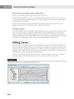
tation begins to create problems. One major problem is called color banding. This occurs when an
image has a gradient color. Instead of a smooth transition of colors over a surface, you see bands,
as shown in Figure 13.19. The effect is similar to that of the Posterize option in many paint
programs.
This color banding may be fine for limited applications such as previewing animations, but
you will want to use true color output for your finished product. True color images, such as those
offered by Targa, TIF, and JPEG files, do not suffer from banding. They also offer smoother edges
on models with lots of straight edges. If you don’t need the absolute best quality, you might con-
sider the JPEG output option. It provides high resolution and true color in a small file size. You
can render a 10-second animation with higher-quality JPEG files and, in some cases, use less
than 40MB of disk space. Most of today’s desktop graphics and video-editing software can read
JPEG files.
Figure 13.19
Two images rendered
in 3ds Max. The one on
the left shows what the
image should look like
under good conditions.
The one on the right
shows color banding
caused by a limited
color palette.
the anIMatIon FIle outPut oPtIons
|
677
File Naming in Animations
When you choose any of the file formats other than AVI or MOV, 3ds Max generates a separate
file for each frame of your animation. The name of each frame is given a number so that the
frame sequence can be easily determined by video-editing programs such as Adobe Premiere
or Autodesk Combustion.
3ds Max will use the name you provide in the Render Output File dialog box. For the rest of
the name, 3ds Max will add a number. For example, if you enter the name Savoye for the ani-
mation file output using the Targa file format, 3ds Max will create a set of files with the names
Savoye0000.TGA, Savoye0001.TGA, Savoye0002.TGA, and so on.
Choosing an Image Size
Still image sizes will vary depending on the medium of presentation. A minimum resolution for
8 × 10-inch prints, for example, is 1024 × 768. Larger poster-size prints will require much higher
resolutions. Video animations for traditional VHS or DVD purposes usually will not exceed
720 × 480. The resolution will be determined by the type of device you are using to record to
videotape or the software used to master your DVD. For example, if you were using the obsolete
step-frame recording method that recorded a single frame at a time directly to videotape, you
would typically render to an image size of 512 × 486. Other real-time video playback devices can
use seemingly odd sizes such as 320 × 486 or 352 × 240. The horizontal resolution is stretched to
fit the size of the screen, so the higher the horizontal resolution you use, the more detail appears
in the final output. The aspect ratio of the animation does not change. You should check the
documentation that comes with your video recording board for the specific sizes you can use for
videotape.
You can use the Print Size Wizard dialog box, shown in Figure 13.20, to quickly determine
the proper rendering resolution when the final destination for the image is printed media. To
open the dialog box, choose Rendering Print Size Assistant.
In the Paper Width and Paper Height fields, enter the printable dimension for the artwork.
This may not be the same as the paper size in situations where the printer, like most office
models, does not print to the extents of the paper. In the DPI field, enter the dots-per-inch value
that the image will be printed to. Click the Render button at the bottom of the Print Size Wizard
dialog box to transfer the values, and then open the Render Setup dialog box. Choose a filename
and type, and then click Render in the Render Setup dialog box to create your image.
Figure 13.20
The Print Size
Assistant is used to
determine the cor-
rect rendering size
for image output to
properly print an
image.
678
|
CHAPTER 13 CreatInG anIMatIons
The AVI Codecs
Earlier in this chapter, you had to choose a video-compression method for your animation files.
Many methods are available, all of which degrade the video quality to some degree. Some of the
methods are intended for presenting video only on a computer, while others are intended for TV
monitors.
Third-Party Codecs
Several third-party codecs are available free or for purchase; one of the most popular is the DivX
codec. When using a codec that does not ship with Windows, keep in mind that anyone who wants
to view your animations must have that codec installed on their system as well. Be aware of this
if you send an animated portfolio to a potential employer using a third-party codec that they may
not have.
If your animation is destined for computer presentation, chances are you’ll use the AVI
file format. AVI allows you to select from a variety of compression/decompression methods,
commonly known as codecs. You’ve already been introduced to a few of these codecs, but as a
reminder, here’s a rundown of the most common codecs and their uses:
Cinepak Designed for high-quality video playback from a computer. This codec is consid-
ered to produce the best quality.
Intel Indeo Designed for high-compression ratios, it is best suited for multimedia.
Intel Indeo RAW Applies no compression to video. Use this to maintain the highest level
of image quality while transporting your file to other digital video programs such as Adobe
Premiere.
Microsoft RLE Designed to keep file size down by reducing the color depth. It is primarily
designed for 8-bit animations.
Microsoft Video Similar to RLE in that it reduces the color depth of the file. It is designed
for 8- and 16-bit animations and videos.
None Applies no compression at all to your file. Like the Intel Indeo RAW format, this
option is for storing image files at their best level of quality, sacrificing disk storage space.
Burning Animations to DVDs
You can render sizable animations and burn them onto an inexpensive DVD-ROM that holds 4.7GB of
data. You can buy a DVD writer for under $25; practically all new computers have them as standard
equipment. Many DVD burners come with the software needed to produce DVDs that are viewable
on consumer DVD players connected to television sets.