Conductive Polymers and Plastics in Industrial Applications Part 2 potx
Bạn đang xem bản rút gọn của tài liệu. Xem và tải ngay bản đầy đủ của tài liệu tại đây (384.36 KB, 20 trang )
subtle systematic variations throughout this intermediate HF-doping sequence. The 22 =30
o
shoulder becomes much less pronounced while the 22 =26
o
shoulder is ultimately identified
as a distinguishable peak. The 995 mM sample scan is clearly different from all the preceding
curves and indicates that addition HF uptake ( to give y
≈
0.5) is associated with a discrete
change to another structural phase. In this case the scattering profile bears a strong resem-
blance to the H
2
SO
4
-doped PANI-ES results of Moon et al.
12
We note that throughout the en-
tire processing sequence of samples in Figure 4 there appears to be a monotonic decrease in
the proportion of scattering which can be attributed to crystalline regions of the films. More-
over these remaining peaks also appear to broaden somewhat. This general trend suggests
that c-PANI is “fragile” and that the continued structural variations irreversibly lower the rel-
ative crystallinity.
There are other important scattering features that can be resolved. The HCl-ES scan of
Figure 3 contains distinctive variations in the widths and shapes of the resolved peaks. Na-
ively one expects that simple crystalline polymers tend to produce scattering peaks whose
full-width at half-maximum are nearly independent of the crystal orientation and broaden
only slightly with increasing 22. In this sample the two peaks located near 22 =26
o
and 28
o
are much narrower than any other resolved peaks including those at lower angles. While an
anisotropic crystal habit may play a role in this result, a more likely possibility is that these
other peaks are comprised of
at least two or more superim-
posed scattering peaks from
a low-symmetry unit cell.
Hence a simple d-spacing
identification is somewhat
deceptive although we in-
clude this in Table 1.
Before introducing pos-
sible structural models for
the aforementioned results it
is first necessary to demon-
strate the significance of
incorporating water uptake
17
into any comprehensive dis-
cussion of the unit cell
structure.
18
Hence the results
of the in situ scattering ex-
periment during water
uptake in a dehydrated
Polyaniline from a Structural Perspective 15
Table 1. Summary of observed d-spacings
Sample
22,
o
d, nm Sample
22,
o
d, nm
HCl-ES
8.9 0.99
Dedoped
EB
6.5 1.40
15.0 0.59 9.8 0.90
20.4 0.44 15.1 0.59
25.4 0.35 20.0 0.44
27.7 0.32 24.3 0.37
30.5 0.29 26.4 0.34
HF-ES
(99 mM)
9.4 0.94 30.0 0.30
14.7 0.60 36.5 0.25
19.4 0.46
HF-ES
(995 mM)
10.0 0.88
23.4 0.38 14.6 0.61
25.5 0.35 19.0 0.47
29.6 0.30 25.5 0.35
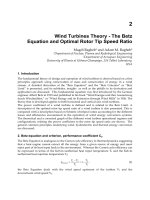
HCl-doped ES-I samples are shown in Figure 5. The bottom two spectra of the left side panel
show in direct relief a comparison of the dehydrated powder and the same powder after expo-
sure to water vapor for just 30 m. While the specific crystalline “peak” positions remain
relatively unchanged, the dehydrated sample data is significantly different in a variety of im-
portant ways. Much of the scattering intensity shifts to lower angle and the relative proportion
of scattering by crystalline regions of the power is sharply diminished. Moreover the relative
peak intensity ratios are seen to shift strongly. There is an exceptionally large increase in the
scattering intensity of the dehydrated sample at the lowest accessible 22 regions. There are
16 Conductive Polymers and Plastics
Figure 5. XRD spectra recorded in situ, from a dried HCl-ES (class I) sample, during continuous exposure to water vapor. The
left panel is arranged so that only the upper five bracketed curves have been vertically offset. The right panel shows the low angle
2
θ
behavior in greater detail without offsets.
also noticeable changes between the two HCl-ES profiles representing a sample before
(Figure 4) and after dehydration. In particular the rehydrated sample exhibits a profile shape
closer to those reported elsewhere and it contains a measurable decrease in the relative frac-
tion of crystalline material.
These features suggest that water has a profound impact on the crystal structure, the rela-
tive crystalline/amorphous proportions and the overall structural homogeneity. Removal of
water from HCl-doped ES seems to produce three main effects: The unit cell packing be-
comes altered without any dramatic changes in the major d-spacings, the level of local
disorder within the unit cell is significantly increased and, finally, the degree of structural
inhomogeneity at larger scales is also increased. Since the small-angle scattering results of
Annis et al.
19
identify changes primarily along the meridional direction, the increases in in-
tensity of the scattering background seen in this work are also expected to occur likewise
(along the meridional direction) and are associated with ordering by both water and halogen
counter-ions within any identifiable channels. Closer inspection of the in situ profiles, ob-
tained at selected times after constant exposure to water vapor, shows continued evolution of
the HCl-doped ES structure. In addition to the rapid recovery of the original ES-I unit cell
structure, albeit with a
loss in crystallinity, the
low-angle scattering in
the 22 =2
o
to 4
o
region
smoothly decreases over
time. This suggests a
gradual return to a more
uniform water/halo-
gen-ion ordering along
the c-axis. Coupled with
this are gradual increases
in the scattering intensity
in the vicinity of 4
o
,7
o
,
27
o
at 30
o
(and denoted by
arrows in Figure 5).
Hence there are slow
changes in the unit cell
structure itself.
While comprehen-
sive modeling studies are
currently underway, it is
still possible to provide
Polyaniline from a Structural Perspective 17
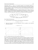
Figure 6. Various proposed new structural models for the studied emeraldine class I
powders appropriate in (a) dehydrated HCl-ES, (b) HCl-ES containing two water
molecules per nitrogen, (c) dedoped EB, (d) redoped HF-ES [from 25 mM to 99 mM HF
aqueous solution treated powders] and (e) fully redoped HF-ES [using a 995 mM HF
aqueous solution].
preliminary structural models which reproduce many of the aforementioned scattering fea-
tures. These are displayed in sequential order in Figure 6. All of the doped structures have
some characteristics in common with the nominal model proposed by Pouget [shown in
Figure 3(b)] but there are notable differences. The model for dehydrated HCl-ES requires that
the PANI chain axis rotation alternates along the a-axis. This doubles the effectively equato-
rial unit cell dimensional area and creates two different PANI interchain nearest neighbor
spacings along the b-axis direction. The larger of these two may serve to facilitate water diffu-
sion upon reexposure to water vapor. In panel 6(b) the rehydrated structure is displayed with
two H
2
O molecules per N-atom. In this structure all PANI chains now have equivalent chain
rotations thus halving the a-axis repeat. To accommodate the pronounced water uptake the
PANI chain axis rotation is large (relative to the a-axis) and the Cl
-
ions are laterally displaced
from the high-symmetry position of Figure 3(b). Modeling the dedoped EB sample requires a
large, disordered unit cell but the overall ES-I PANI chain packing remains. Finally on
HF-doping there is a sequential two-step process whereby only half the available F
-
channels
site are filled initially. The final HF-doped ES sample most resembles the dehydrated HCl-ES
structure although the former requires water. In sum total this structural response is far richer
than originally imagined.
ACKNOWLEDGMENTS
The financial support by NSF Grant No. DMR-9631575 (MJW) is gratefully acknowledged.
REFERENCES
1 M. E. Jozefowicz et al., Phys. Rev., B39, 12958 (1989).
2 J. P. Pouget et al., Macromolecules, 24, 779 (1991).
3 A. J. Epstein et al., Synth. Met., 65, 149 (1994).
4 Z. H. Wang et al., Phys. Rev. Lett., 66, 1745 (1991).
5 M. Reghu, Y. Cao, D. Moses, and A. J. Heeger, Phys. Rev., B47, 1758 (1993).
6 A. G. MacDiarmid and A. J. Epstein, Synth. Met., 69, 85 (1995).
7 Z. H. Wang, J. Joo, C H. Hsu, and A. J. Epstein, Synth. Met., 68, 207 (1995).
8 N. S. Sariciftci, A. J. Heeger, and Y. Cao, Phys. Rev., B47, 1758 (1994).
9 W. S. Huang, B. D. Humphrey, and A. G. Mac-Diarmid, J. Chem. Soc., Faraday Trans., 82, 2385 (1986).
10 A. Andreatta et al., in Science and Applications of Conducting Polymers, edited by W. R. Salaneck, D. T. Clark, and
E. J. Samuelsen (Adam Hilger, Bristol, 1991), p. 105.
11 A. G. MacDiarmid and A. J. Epstein, Science and Applications of Conducting Polymers (Adam Hilger, Bristol,
England, 1990), p. 141.
12 Y. B. Moon, Y. Cao, P. Smith, and A. J. Heeger, Polymer, 30, 196 (1989)
13 M. Laridjani et al., Macromolecules, 25, 4106 (1992).
14 J. Maron, M. J. Winokur, and B. R. Mattes, Macromolecules, 28, 4475 (1995).
15 T. J. Prosa et al., Phys. Rev., B51, 150 (1995).
16 The absolute F
-
concentrations were not ascertained.
17 M. Angelopoulos, A. Ray, A. G. MacDiarmid, and A. J. Epstein, Synth. Met., 21, 21 (1987).
18 B. Lubentsov et al., Synth. Met., 47, 187 (1992).
19 B. K. Annis, J. S. Lin, E. M. Scherr, and A. G. MacDiarmid, Macromolecules, 25, 429 (1989).
18 Conductive Polymers and Plastics
Processability of Electrically Conductive Polyaniline
Due to Molecular Recognition
Terhi Vikki
Department of Technical Physics, Helsinki University of Technology, FIN-02150 Espoo,
Finland
Olli Ikkala
Department of Technical Physics, Helsinki University of Technology, FIN-02150 Espoo,
Finland and Neste Oy, P.O. Box 310, FIN-06101 Porvoo, Finland
Lars-Olof Pietilä
VTT Chemical Technology, P.O. Box 1401, FIN-02044, Finland
Heidi Österholm, Pentti Passiniemi, Jan-Erik Österholm
Neste Oy, P.O. Box 310, FIN-06101 Porvoo, Finland
INTRODUCTION
The electrically conductive emeraldine salt form of polyaniline
1
has long been regarded as an
intractable material, i.e. infusible and poorly soluble, due to the aromatic structure, the
interchain hydrogen bonding, and the charge delocalization effects. Emeraldine salts are
known to dissolve only in certain amines, and hydrogen bonding solvents, in particular in
strong acids. Melt and solution processability can be improved if PANI is protonated with
specific bulky protonic acids. Well-known examples of such acids are p-dodecyl benzene
sulphonic acid (DBSA),
2
camphor-10-sulphonic acid (CSA)
2
and methyl benzene sulphonic
acid (TSA).
PANI(DBSA)
0.5
-complex is soluble in excess DBSA,
3
probably because its highly
acidic -SO
3
H-groups are able to make a particularly strong hydrogen bonding to the aminic
sites of PANI. Less acidic compounds lead to lower solubility due to smaller strength of hy-
drogen bonding. For example, aliphatic alcohols, long chain aliphatic carboxylic acids,
phthalates and most other carboxylic acid esters and ketones are not solvents for electrically
conductive PANI. However, in spite of their low acidity, phenols are good solvents for
emeraldine salt, if the protonation has been made using CSA.
2,4
The above considerations show that strong specific interaction between the emeraldine
salt and an organic compound is important to achieve high solubility. Here we point out a
novel concept to achieve high solubility of emeraldine salt where increased specific interac-
tion to the solvent is obtained by sterically matching several small interactions
5,6
i.e.,
molecular recognition.
7
Examples of solvents fulfilling these conditions are dihydroxy
benzenes and phenyl phenols. In this work solubility of PANI(DBSA)
0.5
in resorcinol i.e.,
1,3-dihydroxy benzene is studied. We also show that PANI(CSA)
0.5
/m-cresol is a limiting
case of the concept.
5
EXPERIMENTAL METHODS
PANI(DBSA)
0.5
-complex was prepared by conventional methods.
4
PANI(DBSA)
0.5
and res-
orcinol were dried and mixed usinga3gminiature mixer at constant temperature in N
2
atmo-
sphere for 10 minutes. The mixing temperatures were 160, 180, 200, 220 and 240°C, and the
weight fraction of resorcinol was 100, 90, 80, 70 and 60 wt%. FTIR was used to verify that no
chemical reactions or major thermal degradation had occurred.
Optical microscopy in combination with a hot stage was used to study the solubility of
PANI(DBSA)
0.5
in resorcinol. A small amount of mixture was inserted between two micro-
scope glass slides and kept for two minutes at the temperature were the mixing had taken
place. The morphology of the mixture was simultaneously inspected with a microscope. If a
distinct “two-phase” structure containing dispersed PANI particles in a solvent rich medium
was observed, it was concluded that PANI(DBSA)
0.5
was not dissolved in resorcinol. On the
contrary, a green transparent “one-phase” morphology without a dispersed phase suggests
solubility. Note, however, that based on optical microscope alone, one cannot unambiguously
conclude whether a true solution or colloidal dispersion is obtained.
DSC measurements were conducted with a Perkin Elmer DSC 7 equipment at a heating
rate 10°C/min.
COMPUTATIONAL METHODS
In order to model PANI(DBSA)
0.5
/resorcinol systems, the long alkyl tail of DBSA was ex-
cluded, as it was not expected to qualitatively effect bonding. Therefore, the binding of resor-
cinol molecules to sulphonic acid doped PANI-complex was studied using TSA as the
counter-ion. UHF/AM1 optimized structure of PANI chain consisting of three rings and
doped with two TSA molecules was studied. Eight resorcinol molecules were added to the
system and 200000 steps (time step 1 fs) of molecular dynamics were performed at 300 K.
The resulting structure was saved after each 1000 steps and the 200 structures were opti-
mized. The Insight/Discover software with the pcff force field by Biosym Technologies was
used in these calculations.
20 Conductive Polymers and Plastics
Conformations of CSA-protonated PANI chains and the PANI(CSA)
0.5
/m-cresol system
were modeled using the semiempirical quantum chemical method AM1 implemented to the
MOPAC software package. The models were limited to PANI compounds consisting of three
rings and checked with eight rings.
RESULTS AND DISCUSSION
Solubility of PANI(DBSA)
0.5
in res-
orcinol depends both on temperature
and PANI-complex weight fraction.
Figure 1 depicts the morphologies of
PANI(DBSA)
0.5
/resorcinol mixtures
at elevated temperatures by optical
microscopy. High temperatures and
low PANI-complex weight fractions
promote dissolution, manifested as a
one-phase morphology.
PANI(DBSA)
0.5
can be dissolved in
resorcinol up to 40 wt% at tempera-
tures below 240°C. This behavior
suggests one branch of phase bound-
ary corresponding to the upper criti-
cal solution behavior with a high
critical temperature.
The same morphologies as in
Figure 1 are observed also at room
temperature immediately after rapid
cooling. No crystallinity is observed
in PANI(DBSA)
0.5
/resorcinol mix-
tures. However, after an induction
period spherulitic crystals start to
emerge, see Figure 2. This is in con-
trast to pure resorcinol which
crystallizes immediately after cool-
ing to room temperature. Long
induction time is observed for sam-
ples with high mixing temperature,
i.e., for samples that have been well
Processability of Polyaniline 21
Figure 1. Dissolution phase diagram of PANI(DBSA)
0.5
and resorcinol
mixtures.
Figure 2. Induction time for resorcinol crystallization as a function of the
mixing temperature.
dissolved according to Figure 1. This observation
suggests that the dissolved PANI(DBSA)
0.5
mole-
cules delay the crystallization of resorcinol. A
similarly slow development of crystallinity was
also observed for mixtures of PANI(CSA)
0.5
and
resorcinol by WAXS in a related study.
6
The DSC traces for the second heating of the samples mixed at 200°C are shown in Fig-
ure 3. The mixtures were aged a few weeks at room temperature before measurement. By
comparing different aging times, it was concluded that resorcinol was fully crystallized.
Melting point depression of resorcinol is observed suggesting interaction between the com-
ponents (Figure 3). Pure resorcinol crystallizes at about 115°C and the melting point is
depressed to 98°C as 40 wt% PANI(DBSA)
0.5
is mixed with resorcinol at 200°C. Also the
heat of fusion shows interaction between the components (Figure 4). The heat of fusion deter-
mined from the first heating thermogram depends linearly on the weight fraction of
resorcinol. It vanishes for mixtures with less than 2.8 moles of resorcinol associated per PhN
repeat unit of PANI. This suggests that only part of resorcinol is able to crystallize as the rest
is strongly associated with PANI(DBSA)
0.5
.
The association of 8 resorcinol molecules to the system comprising three PANI repeat
units doped by two TSA molecules is shown in Figure 5, i.e., there are 2.7 moles of resorcinol
vs. 1 mol of PhN repeat unit of PANI. The first 4 resorcinol molecules form strong hydrogen
bonds directly to the two sulfonate groups of TSA. The strong dipole moment of the sulfonate
22 Conductive Polymers and Plastics
Figure 3. DSC traces of PANI(DBSA)
0.5
/resorcinol
samples mixed at 200
o
C.
Figure 4. Resorcinol heat of fusion in PANI(DBSA)
0.5
/resorcinol
samples mixed at 200
o
C.
groups is able to orientate these
“first-layer” resorcinol molecules due to
the hydrogen bonding OH-groups. The
“first-layer” resorcinol molecules effec-
tively shield the sulfonate groups. The
nature of the available hydrogen bond-
ing to additional resorcinol molecules is
therefore changed, and the additional 4
resorcinol molecules are bonded both
by two hydrogen bonds and one
phenyl/phenyl interaction on top of the
PANI rings. There are several specific
reasons that allow the phenyl/phenyl
stacking of the “second-layer” mole-
cules. Firstly, the stacked structures are
possible because the distance of the
OH-groups of resorcinol matches the
corresponding distances of the hydro-
gen bonding moieties of the
PANI(DBSA)
0.5
, thus allowing steric fit
of two hydrogen bonds and one
phenyl/phenyl interaction, i.e., molecu-
lar recognition. Secondly, resorcinol is a
rigid structure, for which the thermal
movements do not change the distances.
Thirdly, the phenyl/phenyl interaction
plays an important role, as further mani-
fested by phenyl phenols and bisphenols
which are examples of other solvents. In these cases also the periodicities of the phenyl rings
within the solvents approximately match the periodicity of PANI chains, allowing steric fit of
the successive phenyl rings in combination with the hydrogen bonds.
Finally it is shown that PANI(CSA)
0.5
dissolved in m-cresol is a limiting case of the
above molecular recognition concept.
5
In this case there are three possible sites for the associ-
ation of m-cresol molecules. First, there is the sulfonate anion of CSA, secondly the PANI
amine group and finally the carbonyl group of CSA. The last bonding site is specific to CSA
and does not exist in DBSA, for example. Figure 6 demonstrates the optimized structure
showing >C=O
⋅⋅⋅
HO hydrogen bonding between CSA and m-cresol and the stacking of the
m-cresol phenyl ring on top of the PANI phenyl ring. In this case the net interaction of
Processability of Polyaniline 23
Figure 5. Association of 8 resorcinol molecules with PANI protonated
by TSA.
Figure 6. Association of m-cresol molecules with PANI protonated by
CSA.
m-cresol consists of one hydrogen bond and one phenyl/phenyl interaction, leading to a cycli-
cally associated species. This observation is in agreement with the observed high solubility of
PANI(CSA)
0.5
in m-cresol, while the solubility of PANI(DBSA)
0.5
in m-cresol remains
poor.
4,5
CONCLUSIONS
We suggest that molecular recognition can be systematically applied to identify a large class
of novel low acidic solvents for PANI protonated by essentially any organic acid. In this con-
cept the phenyl rings of PANI are considered as potential sites of phenyl/phenyl interaction
with a periodicity of ca 6 Å. At the same periodicity there are also hydrogen bonding sites,
consisting of amines and sulfonates due to protonating sulfonic acids. The first requirement
for low acidic solvents is that the solvent has to comprise phenyl rings and sufficiently strong
hydrogen bonding functional groups at the same periodicity. Secondly, for PANI protonated
by generic sulfonic acid such as DBSA, TSA, or methane sulfonic acid an additional require-
ment is that at least one hydrogen bond and at least one phenyl/phenyl interaction is made, the
total number of such interactions being
≥
3. Suitable compounds are dihydroxy benzenes,
phenyl phenols, bisphenols, hydroxy benzoic acids. In the special case where the counter ion
itself allows a suitable hydrogen bonding, such as CSA, the critical number of the interactions
is reduced to 2. An example of this case is PANI(CSA)
0.5
dissolved in m-cresol.
In order to demonstrate the feasibility of the concept, dissolution of PANI(DBSA)
0.5
in
resorcinol is illustrated in more detail.
REFERENCES
1 J C. Chiang, A.G. MacDiarmid, Synth. Met., 1986, 13, 193.
2 Y. Cao, P. Smith, A.J. Heeger, Synth. Met., 1992, 48, 91.
3 T. Kärnä, J. Laakso, E. Savolainen, K. Levon, European Patent Application EP 0 545 729 A1, 1993.
4 Y. Cao, J. Qiu, P. Smith, Synth. Met., 1995, 69, 187
5 O.T. Ikkala, L O. Pietilä, L. Ahjopalo, H. Österholm, P.J. Passiniemi, J. Chem. Phys., in press.
6 T. Vikki, L O. Pietilä, H.Österholm, L. Ahjopalo, A. Takala, A. Toivo, K. Levon, P.Passiniemi, andO. Ikkala, submitted.
7 For a review, see Rebek, J. Jr., Topics in Current Chem., 1988, 149, 189.
24 Conductive Polymers and Plastics
Crystallinity and Stretch Orientation in Polyaniline
Camphor-Sulphonic Acid Films
L. Abell, P. Devasagayam, P. N. Adams and A. P. Monkman
Department of Physics, University of Durham, England
BACKGROUND
Conceptually, being able to replace metals with conductive polymers is a very attractive prop-
osition. Practically, the last decade has shown that although there is a great deal of promise,
we still have a way to go before commercial products are realized. To this end polyaniline
(PANI) has been shown to be the most promising material to fulfill such applications
1
being
air stable, cheap to produce in large scale and most importantly processible to some degree.
2
One problem with this polymer has always been how to efficiently dope it once it has been
processed. This problem tends to rule out using ‘base’ polymer processing, i.e. solution pro-
cessing unprotonated or base PANI in N-methyl-2-pyrrolidone.
3
as such material requires
post process acidification to render the polymer conductive, which is difficult to achieve ho-
mogeneously in a dense film.
4
This problem has, however, been circumvented by the discov-
ery of acid solution processing routes. These were first described by Cao et al.
5
using two
specific functional acids, camphor-sulphonic acid (CSA) and dodecyl benzene sulphonic
acid (DBSA) in various organic solvents.
One such system has proven to be of considerable interest however. This is PANI:CSA
cast from m-cresol solution. Using this particular system enables films to be produced which
show metallic transport, i.e. an increase in conductivity with decreasing temperature above
some critical temperature below which the conductivity drops again with lowering tempera-
ture.
6
Intriguingly, it seems that only this particular system yields such well defined transport
properties. To try to find out why this is, we have performed a range of measurements on
PANI:CSA films aimed at probing the role which CSA and m-cresol play in both
microstructure and electrical transport and to understand why it is that only this combination
gives such desirable physical properties. To do this we have employed x-ray crystallography
along with various film processing conditions, film orientation via application of uniaxial
stress and temperature dependent transport analysis to monitor how both microstructure and
transport are controlled by CSA and m-cresol content along with film processing conditions.
EXPERIMENTAL SECTION
High molecular weight polyaniline was prepared at -25
o
C using the standard Durham proce-
dure.
7
Gel permeation chromatography in N-methyl-2-pyrrolidone solvent (+ 0.1% LiCl)
with polyvinylpyridine molecular weight standards
8
indicated that the polymer had a weight
average molecular weight, M
w
, of 174000 and number average molecular weight, M
n
,of
21000 Daltons. The polydispersity was therefore 8.3.
To obtain stretch oriented CSA doped polyaniline films, good quality isotropic
feedstock with a thickness variation of less than 5% is imperative. This was achieved by sol-
vent casting in the usual way, i.e. a 50% CSA doped, 1.6% PANI in m-cresol polymer solution
was poured onto a polished sili-
con wafer and dried at 60
o
C
under a dynamic vacuum for 20
hours. A quantity of chloroben-
zene was added to the solution to
prevent gelation. This process
gives a sample thickness varia-
tion of less than 5%. Dumbbell
shaped specimens with a gauge
aspect ratio of 6 were then guillo-
tined from the feed stock.
Differential scanning calorimetry
studies have shown that the glass
transition temperature of
PANI:CSA (m-cresol) is approxi-
mately 145
o
C,
9
thus the
deformation temperature was
chosen to be 150
o
C. Attempts to
draw samples at lower tempera-
tures have all failed at low strains
(< 25% extension).
The specimens were de-
formed using an Instron 4505
tensile testing machine which
26 Conductive Polymers and Plastics
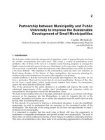
Figure 1. 2
θ
scans of PANI:CSA with various doping levels.
had been preheated to 150
o
C for an hour. Fiducial markers were drawn onto the surface of
each specimen at 3 mm intervals so that the amount of deformation parallel to the draw direc-
tion could be determined. The specimens where then placed, in turn, into the oven where they
were left until the oven reached thermal equilibrium. Thermogravimetric analysis of a typical
sample shows that (5+
2)% of the sample’s weight is lost during this period due to loss of
m-cresol and chlorobenzene. As 15-20% of the as cast sample's weight is due to the retention
of m-cresol and chlorobenzene, sample ‘hardening’ due to removal of the plasticisers during
the thermal emersion before stretching should not be a significant problem. The specimens
were then deformed uniaxially at a rate of 5mm/min, a strain rate of 0.2 min
-1
.
To probe the transition to the ‘‘metallic’’ conductive state upon protonation with CSA,
the temperature dependence of the electrical conductivity of films was measured as a function
of doping level. Films were prepared with CSA contents intended to yield 30, 40, 50 and 60%
protonation levels. Conductivity was measured under vacuum (< 10
-3
Torr) over the tempera-
ture range 10 to 300 K using a four in line constant current technique.
10
Samples were held for
5-6 hours in the vacuum environment of the cryostat prior to the measurement process to en-
sure that any volatiles were extracted. The conductivity of PANI:CSA after such treatment
was typically 80 to 85% of that measured in normal atmospheric conditions. The 2
θ
WAXS
diffraction patterns of the various films were collected using a Philips diffractometer and
CuK
α
radiation in reflection (see Figure 1), air scattering and line broadening due to slit ef-
fects were corrected for. A careful study of diffraction patterns obtained from several forms of
CSA show that the features we observe in PANI:CSA are not due to CSA crystallites within
the films. To measure the effect of solvent removal from films, samples were placed in high
vacuum (<10
-6
torr using a turbo molecular vacuum pump) for 48 hours prior to examination.
Texture induced in the drawn samples was studied using a Huber 4 circle goniometer
with CuK
α
radiation. This technique relies on the fact that the measured intensity after correc-
tions is proportional to the number of crystallographic plane normals or ‘poles’ which are
parallel to the scattering direction, a reference direction which bisects the angle between the
source and detector and lies in the plane formed by the source, detector and sample. Thus the
orientation distribution of a chosen set of (hkl) crystallographic planes can be measured by
fixing the detector at the appropriate 2
θ
angle so that it receives radiation scattered from these
planes and then rotating the sample, the scan is parameterized by defining two spherical an-
gles. The angle between the scattering direction and the sample plane normal is defined as
α
,
and the angle between the projection of the scattering direction onto the sample and the sym-
metry axis of the sample perpendicular to the draw direction and in the plane of the film (the
transverse direction) is defined as
β
.
The effect of varying the amount of CSA dopant on crystal structure can clearly be seen
in Figure 1. We are currently in the process of fitting and refining this data to yield crystal
structures, however trends present in the 2
θ
scans are very informative. The main features
Crystallinity and Stretch Orientation 27
which will be seen to be the most
sensitive to m-cresol content are a
very sharp peak at ca. 2
o
-4
o
corre-
sponding to a d-spacing of 20A.
This feature is strongly dependent
on the doping level and is most
pronounced at 60% CSA level
corresponding to the most metal-
lic samples that we have produced
and scales directly with the metal-
lic conductivity contribution (see
Figure 2). The half width of this 2
θ
peak implies a coherence length
within the film of many hundreds
of Angstroms and so must be a
feature associated with crystal re-
gions, not amorphous regions as
implied by others.
11
RESULTS
Further features which are clearly dependent on the level of CSA in the sample are seen at ca.
6A, 4.5A and 3.5 A d-spacing. The widths of these peaks vary quite markedly. This is in fact
due to anisotropy within the films even though they were produced simply by casting. This
has been shown clearly by Minto and the group at the University of Reading.
12
In the reflec-
tion geometry that we have used to obtain our spectra a peak at 9.2A is not very visible
whereas others observe such a feature for example.
12
Conductivity data for films at all doping
levels are presented in Figure 2. It is clear that as the level of protonation is increased, the con-
ductivity increases rapidly, also the conductivity becomes a weaker function of temperature
in the more heavily protonated films. Each data set in the 30% to 60% doping range possesses
a characteristic maximum in
σ
(T) somewhere in the measured range. The temperature at
which this peak occurs has an inverse relation to the level of doping of the sample in question.
The trend revealed by samples prepared with protonation levels in the range between 30%
and 60% are consistent. At low temperature, the conductivity displays an activated behavior.
As the level of protonation is increased from 30% the decrease in conductivity at the lowest
temperatures is much reduced, compared to each films room temperature value. At the theo-
retical 50% maximum doping point
13
the peak in conductivity is observed at approximately
180 K. However, at 60% doping the magnitude of the conductivity is increased significantly,
28 Conductive Polymers and Plastics
Figure 2. Conductivity data from PANI:CSA as a function of doping level.
this is consistent with the x-ray data, the peak value of conductivity also occurs at a tempera-
ture significantly lower than that of 50% doped samples. The reduction in conductivity at
temperatures below the peak is also less pronounced. This evidence implies that doping
above the 50% level is capable of driving the PANI:CSA system far closer to true metallic be-
havior which is mirrored by the increase in the enhanced crystallinity of the 60% films.
To probe where the m-cresol
may be residing in the system a
nominally 50% doped film was
taken and after recording a 2
θ
scan,
subjected to 48 hours in high vac-
uum. After this treatment another 2
θ
was recorded. The before and
after scans are shown in Figure 3.
Removal of m-cresol is seen to
have a marked effect on the
crystallinity of the sample. Peak
positions were accurately deter-
mined with respect to Al peaks
emanating from the sample holder
(not shown in the figure for clarity).
After pumping all peaks are seen to
shift to higher 2
θ
angles indicating decreasing d-spacing. The relative intensities of the fea-
tures also changes markedly. The 20A feature losses intensity whereas all other features gain
intensity with some small line shape changes and line broadening also being noted. Such
pumped films also suffer loss of conductivity, and in most cases the turn over temperature
moves to higher temperatures. Importantly, when we have measured 60% films in a liquid He
cryostat with sample in exchange gas we find that the magnitude of low temperature conduc-
tivity increases and the turn over temperature is observed at 70K,
14
observations consistent
with the pumping experiment. A comparison of the 2
θ
diffractometer scans of the isotropic
and drawn samples (Figures 1 and 4), which have been corrected for thickness and any geo-
metrical effects, shows that there is a decrease in scattering from both
the amorphous phase
and the equatorial crystalline reflection. at 2
θ
=25.5
o
(the poles of which lie in the a-b plane of
the unit cell) of the drawn sample. Little change is observed in the crystalline peak at
2
θ
=20.75
o
, and no new diffraction peaks are observed within the range 2
θ
=2-100
o
due to the
production of a new crystal structure during deformation.
Crystallinity and Stretch Orientation 29
Figure 3. WAXS scans of pumped and unpumped CSA doped polyaniline.
DISCUSSION
From the transport data it is evi-
dent that PANI:CSA is an exam-
ple of a conductor close to a
metal-insulator (MI) transition.
As the level of doping is in-
creased from 30% to 60% the
trends in conductivity imply that
there is a transition in the nature
of charge transport from hopping/
tunneling due to localization of
carriers on some scale, to partial
‘metallic’ diffusive transport. The
exact mechanism by which this
transition occurs must be related
to the crystal structure of the sam-
ple. If we view PANI-CSA as a
composite material and invoke
the heterogeneous conductor model with two charge transport mechanisms at work, these be-
ing metallic diffusion within crystalline regions and temperature activated transport in the
disordered regions. A detailed discussion of these processes is given elsewhere.
10
It is clear
that the ‘‘metallic’’ conductivity is not only controlled by the doping level (which is control-
ling the crystal structure) but also by the content of m-cresol in the sample (again this is also
controlling the crystallinity). From our x-ray analysis the optimum dopant level for maximum
crystallinity is 60%, this agrees very well with the transport data. In both cases the degree of
crystallinity scales well with the magnitude of electrical conductivity and the strength of the
metallic signature. The role the solvent, m-cresol plays in all of this is obvious to see but at
present it is difficult to interpret exactly what is going on. To fully elucidate the subtle struc-
ture property correlation's of this system requires extensive modeling and fitting of the wide
range of experimental data now available. However from the trends presented here a few pro-
cesses are apparent. On removal of m-cresol from a film the magnitude of its conductivity
drops, as does the metallic contribution to the overall conductivity. Looking at the crystal
structure of the two states we see that the 20A feature reduces in intensity, since this feature
scales so well with metallic conductivity in the doping studies, it is consistent with the fact
that in the pumped films the metallic nature is much reduced. The increase in the amorphous
background on removal of the m-cresol indicates that the solvent is required within the crys-
30 Conductive Polymers and Plastics
Figure 4. Comparison of 2
θ
scans from a drawn (67% elongation) PANI:CSA
film.
talline phase in order to prevent some process which would otherwise disrupt the unit cell. We
do not understand why the 3.5 A feature behaves as it does unless it is a signature of ‘‘effec-
tive’’ dedoping, or rather a shift in the CSA dissociation equilibrium such that less charge ap-
pears on the PANI chain. This would have many effects including changes to the backbone
geometry and a reduction of coulombic repulsion between adjacent chains. On a molecular
level we have to assume that the m-cresol is involved with the CSA to aid dissociation and
thus drive protonation of the PANI chain, and it prevents the carbonyl group of the CSA from
H-bonding to the PANI chain. What exactly occurs upon its removal is impossible to say with
the data we have at present. However, as the CSA is a bulky counter ion, to achieve efficient
close packing of chains, neighboring CSA counter ions have to interdigitate, removal of the
m-cresol will allow the CSA to H-bond to the chains disrupting this efficient packing. This
will cause shrinkage of the unit cell, consistent with the observed decreases in d-spacing,
breaking of long range order and most importantly weakening of cofacial interchain ring
overlap destroying metallic charge transport. On a macroscopic scale it is assumed that the
polymer structure can be described by a fringed micelle model.
15
Removal of the m-cresol
from this type of structure will very readily lead to loss of long range order and local shrink-
age of the unit cell, consistent with what is observed upon pumping out the solvent. A great
deal more work is required to fully understand this problem note that the x-ray peaks shown
here are few and planes of electron density within the sample, many processes will lead to
‘‘peaks’’ being absent and the random alignment of crystallites will confuse relative peak in-
tensities, only modeling and fitting can resolve these problems effectively. Once solved how-
ever we shall be in a position to start to be able to design truly metallic conjugated polymers.
The effects observed upon drawing are not simple. The behavior of the crystallites in
particular are unusual if uniaxial orientation is occurring, with the chain axes orienting to-
wards the draw direction. In this case one would expect orientation of the a-b crystallographic
axes (which are themselves randomly oriented about the c crystallographic axis) into the
plane formed by the transverse direction and normal to the plane of the film (nor-
mal-transverse plane). Some orientation and crystallization of the amorphous regions would
also be expected. Thus for uniaxial orientation an increase in scattering from the crystalline
reflections accompanied by a decrease in scattering from the amorphous phase is expected.
Alternatively any decrease in crystallinity should be accompanied by an increase in scattering
from the amorphous phase due to destruction of crystalline order during processing. A de-
crease in scattering from both
phases, which a comparison of Figures 1 and 4 shows, suggests
the development of preferred orientation away from
α
=0
o
and crystallization\orientation of
the amorphous phase. To check this, an
α
scan with the scattering direction in the nor-
mal-transverse plane (
β
=0
o
), and a
β
scan with the scattering direction in the plane of the film,
α
=90
o
, of the 2
θ
=25.54
o
peak, the equatorial reflection showing the biggest effect, were
performed.
15
This work showed that the poles of this reflection are orienting into the nor-
Crystallinity and Stretch Orientation 31
mal-transverse plane, which is consistent with the crystallographic c (or chain) axes orienting
towards the draw direction, and the development of a preferred direction at
α
=10
o
. This is
supported by the 2
θ
scans shown in Figure 4 which where taken at
α
=10
o
and 90
o
. It can be
seen from this that the intensity of scattering from the crystal phase increases and then de-
creases, which supports the idea of non-uniaxial orientation of the crystallites developing.
The increased intensity at
α
=10
o
corresponds to scattering from crystal planes which are ori-
ented at 10
o
to the plane of the film. This we feel may represent a plane formed by the
phenylene rings along the polymer backbone which are inclined at 10
o
.
SUMMARY
Our initial work on the PANI:CSA system indicates that by careful sample preparation very
consistent results can be achieved. By varying the percent of CSA in the films, one starts to
get some insight into the role played by the CSA. X-ray data reveals that sample crystallinity
depends on the doping level. Transport measurements mirror this. We observe the onset of a
metallic conductivity component at ca. 30% doping. This becomes more dominant on in-
creased doping level to 60% doping. At this CSA doping level the samples remain “metallic”
to 135 K. In agreement with the development of maximum sample crystallinity. Thus we ob-
serve a good correlation between crystallinity and metallic conductivity. On removal of
m-cresol we observe changes in the crystalline phase, especially the loss of the 20 A feature.
Such pumped samples are much less metallic and have lower overall conductivity. Stretch
orientation further enhances the physical properties of the films, giving room temperature
conductivities up to ca. 960 S cm
-1
at 120% elongation.
ACKNOWLEDGMENTS
This work is sponsored by BICC Cables and EPSRC via a ROPA award (GRK 35433). We
wish to thank all our collaborators for their support.
REFERENCES
1 See for example, Science and Applications of Conducting Polymers, ed. W. R. Salaneck, D. T. Clark and
E. J. Samuelsen, Adam Hilger, IOP Publishing Ltd.
2 A. P. Monkman and P. N. Adams, Solid State Comm., 78 (1991) 29.
3 A. P. Monkman and P. N. Adams, Synth. Met., 41/2 (1991) 891.
4 A. P. Monkman and P. N. Adams, Synth. Met., 41/2 (1991) 627.
5 Y. Cao, P. Smith and A. J. Heeger, Synth. Met., 48 (1992) 91.
6 M. Reghu, Y. Cao, D. Moses and A. J. Heeger, Phys. Rev. B, 47 (1993) 1758.
7 P. N. Adams, P. J. Laughlin, A. P. Monkman and A. Kenwright, Polymer, 37(15) (1996) 3411.
8 P. N. Adams, D. C. Apperley and A. P. Monkman, Polymer, 34(2) (1993) 328-332.
9 L. Abell and A. P. Monkman, Synth. Met., Accepted for publication.
10 E. Holland et al, J. Phys.Cond. Mat., (1996) 2991.
11 O. T. Ikkala et. al, J. Chem. Phys., 103 (1995) 4855.
32 Conductive Polymers and Plastics
12 C. Minto and A.S. Vaghan, Polymer, in press.
13 J-C. Chiang et al, Synth. Met., 13 (1986) 193.
14 K. Chow et al, Synth Met. Accepted.
15 L. Abell, P. N. Adams, and A. P. Monkman, Polymer Comm., in press.
Crystallinity and Stretch Orientation 33
Structure-Property Characteristics of Ion Implanted
Syndiotactic Polystyrene
Chang-Meng Hsiung and Caiping Han
Louisiana Productivity Center, Chemical Engineering Department/University of SW
Louisiana, Lafayette, LA 70504-4172
Y. Q. Wang, W. J. Sheu, and G. A. Glass
Acadiana Research Laboratory /University of SW Louisiana, Lafayette, LA 70504
Dave Bank
The Dow Chemical Company, Midland, Michigan 48667
INTRODUCTION
Syndiotactic polystyrene (sPS) is a newly developed engineering semi-crystalline polymer
that is based on metallocene technology. It has some attractive physical characteristics in-
cluding high melting point (270
o
C), low specific gravity (1.045), excellent hydrocarbon re-
sistance, a high degree of dimensional stability, enhanced mechanical performance at
elevated temperature, very good electrical properties, and low viscosity at typical shear
rates.
1,2
This combination of properties opens a wide variety of applications including auto-
motive, appliance, medical, electrical/electronic, fibers, and films. The structure-property
characteristics of injection molded neat and glass fiber reinforced sPS parts have been studied
by Hsiung and Cakmak.
3,4,5
Ion implantation is a well-known technique in the electronic industry to modify the elec-
tronic and physical properties of materials. In the recent years, this technique has been widely
applied to many new materials, including organic polymers. Applications of ion implantation
to polymers is of growing interest mainly because polymers are inexpensive, light and can be
easily shaped into various forms. However, most polymers exhibit poor surface properties.
Ion implantation can significantly modify the surface, mechanical, and electrical perfor-
mance of polymers.
6
We studied the structure-property characteristics of carbon ions implanted sPS under
different doses and energy levels.