Frontiers in Robotics, Automation and Control Part 6 pot
Bạn đang xem bản rút gọn của tài liệu. Xem và tải ngay bản đầy đủ của tài liệu tại đây (756.18 KB, 30 trang )
Robust Underdetermined Algorithm Using Heuristic-Based Gaussian Mixture Model for
Blind Source Separation
143
Three other underdetermined algorithms with state of the art are tested in the following
simulations to compare with the proposed algorithm. Here, the first one is named PF
proposed in (Bofill & Zibulevsky, 2001), the second one is named GE proposed in (Shi et al,
2004), and the last one is our previous work which named FC proposed in (Liu et al, 2006).
In order to confirm validation and robustness of these algorithms, four sparse signals
recorded from real sounds are taken for the source signals whose waveforms are shown in
Fig. 3 and Fig. 4. In the first BSS case, the first three source signals are mixed by a well-
conditioned mixing matrix as
⎟
⎟
⎠
⎞
⎜
⎜
⎝
⎛
=
7071.00.8944-0.9285
7071.00.44720.3714
well
A
(24)
It involves distinguishable mixing vectors whose normal angles are
[]
5000.0 ,2952.0 ,2422.0
~
−
well
μ
respectively. The distribution of mixtures is plotted in Fig. 5. In
the second BSS case, the four source signals are mixed by an ill-conditioned mixing matrix
as
⎟
⎟
⎠
⎞
⎜
⎜
⎝
⎛
−
=
9285.07926.07071.07071.0
3714.06097.07071.07071.0
ill
A
(25)
It involves undistinguishable mixing vectors whose normal angles are
[]
2422.0 ,4175.0 ,5000.0- ,5000.0
~
=
ill
μ
respectively since the first vector and the third vector
are quite close. The distribution of mixtures is plotted in Fig. 6.
The parameters of compared algorithms are referenced from the original setting of their
articles. For example, the grid scale is given 720 and
λ
is entered as 55 in PF. The improved
PSO, through the experience of numerous previous experiments, are given the suitable
parameters,
20=sz
, 5.0
=
D
P , 12.0
0
=
α
, 3.0
1
=
α
and 4.0
2
=
α
. For generation number,
100=G is given in first case and 200
=
G is given in second case. For all algorithms, the
every simulation will be tested by 30 independent runs. And, the performance is evaluated
by mean square error (MSE) as
()
∑
=
−=
n
i
ii
n
MSE
1
2
~
1
μμ
(26)
where
i
μ
~
denotes the ith real mixing vector, and
i
μ
denotes the ith estimation. In final, the
average of MSE by 30 independent runs will be presented. An estimated set of mixing vector
having a small MSE implies a excellent source separation.
Frontiers in Robotics, Automation and Control
144
Fig. 3. The waveforms of source signals represented in time domain.
Fig. 4. The waveforms of source signals represented in frequency domain.
Robust Underdetermined Algorithm Using Heuristic-Based Gaussian Mixture Model for
Blind Source Separation
145
Fig. 5. The distribution of mixtures produced by well-conditioned mixing matrix.
Fig. 6. The distribution of mixtures produced by ill-conditioned mixing matrix.
Frontiers in Robotics, Automation and Control
146
5.2 Results
After two simulations are implemented by the involved algorithms, the compared data
about estimating accuracy are presented in Table 1 and Table 2. The both tables describe the
real mixing vectors, the average of estimated mixing vectors and the MSE of the four
algorithms for well-conditioned case and ill-conditioned case. From these tables, it could be
observed that GE algorithm’s performance is always unacceptable in all cases. PF algorithm
just work acceptably in well-conditioned case, but it fail in ill-conditioned case. FC
algorithm is valid in all cases, but its MSE is not better than that of proposed PSO-GMM
algorithm.
In order to compare the improved PSO and standard PSO, their average fitness curves are
shown in Fig. 7 (well-conditioned case) and Fig. 8 (ill-conditioned case). Form both figures,
it could be observed that improved version has better convergent ability on speed and depth;
particularly, that in Fig. 8.
Compared algorithms PF GE FC PSO-GMM
2422.0
~
1
=
μ
1
μ
0.2497 0.2292 0.2498
0.2421
2952.0
~
2
−=
μ
2
μ
-0.2190 -0.1958 -0.2903
-0.2896
5000.0
~
3
=
μ
3
μ
0.1627 0.1402 0.5134
0.4995
MSE 0.0399 0.0465 8.7110e-05 1.0540e-05
Table 1. Comparison of results between the four algorithms in well-conditioned BSS case.
Compared
algorithms
PF GE FC PSO-GMM
5000.0
~
1
=
μ
1
μ
0.5520 0.6856 0.5000
0.4998
5000.0
~
2
−=
μ
2
μ
-0.4895 -0.6469 -0.4982
-0.4929
4175.0
~
3
=
μ
3
μ
0.5639 0.5687 0.3996
0.4176
2422.0
~
4
=
μ
4
μ
0.7494 -0.0817 0.2426
0.2426
MSE 0.0704 0.0460 8.0060e-05 1.2662e-05
Table 2. Comparison of results between the four algorithms in ill-conditioned BSS case.
Robust Underdetermined Algorithm Using Heuristic-Based Gaussian Mixture Model for
Blind Source Separation
147
6. Discussion
In comparing the proposed PSO-GMM with related BSS algorithms, the performance of
GE algorithm is sensitive to predefined parameters. Tt exhibited a large value in MSE
because of the lack of perfect initiations. Unfortunately, there is no rule or criterion that can
be referred to for choosing suitable initiations. The PF algorithm is available in well-
conditional case, and it does not involves any random initiation. However, the PF algorithm
is not robust enough to deal with a complex problem because its settings of parameters is
not for general-purpose; moreover, there are no instructions to guide a user on how to
adjust them to suit other specific cases. The FC algorithm and PSO-GMM algorithm are
efficient and robust enough to handle whether a general toy BSS case or an advanced BSS
case. For further comparison between the both algorithms, it can be discovered that PSO
method explores variant potential solutions; therefore, its accuracy is more excellent than FC
algorithm. For the different PSO versions, the improved PSO exhibits a better convergent
curve because it have the additional mechanism which enhances and replaces the globel
best solution to rapidly drag particles toward a solution with an exact direction and distance
during whole generations.
Fig. 7. Fitness convergence comparison between improved PSO and standard PSO for well-
conditioned BSS case.
Frontiers in Robotics, Automation and Control
148
Fig. 8. Fitness convergence comparison between improved PSO and standard PSO for ill-
conditioned BSS case.,
7. Conclusion
This study addresses on the BSS problem which involves sparse source signals,
underdetermined linear mixing model. Some related algorithms have been proposed, but
are only tested on toy cases. For robustness, GMM is introduced to learn the distribution of
mixtures and find out the unknown mixing vectors; meantime, PSO is used to tune the
parameters of GMM for expanding search range and avoiding local solutions as much as
possible. Besides, a mechanism is proposed to enhance the evolution of PSO. For
simulations, a simple toy case which includes distinguishable mixing matrix and a difficult
case which includes close mixing vectors are designed and tested on several state of the art
algorithms. Simulation results demonstrate that the proposed PSO-GMM algorithm has the
best accuracy and robustness than others. Additionally, the comparison between standard
PSO and improved PSO shows that improved PSO is more efficient than standard PSO.
Robust Underdetermined Algorithm Using Heuristic-Based Gaussian Mixture Model for
Blind Source Separation
149
8. References
Amari, S.; Chen, T. P. & Cichocki, A. (1997). Stability analysis of learning algorithms for
blind source separation, Neural Networks, vol. 10, issue: 8, pp. 1345-1351
Belouchrani, A.; Abed-Meraim, K.; Cardoso, J. F. & Moulines, E. (1997). A blind source
separation technique using second-order statistics, IEEE Trans. on Acoustics, Speech,
and Signal Processing,vol. 45, issue: 2, pp. 434-444
Bofill, P. & Zibulevsky, M. (2001). Underdetermined blind source separation using sparse
representations, Signal Processing, vol. 81, pp. 2353-2362
Cichocki, A. & Unbehauen, R. (1996). Robust neural networks with on-line learning for blind
identification and blind separation of sources, IEEE Trans. on circuits and systems-I:
fundamental theory and applications, vol. 43
Eberhart, R. C. & Kennedy, J. (1995). A new optimizer using particle swarm theory,” Proc. of
the Sixth International Symposium on Micro Machine and Human, pp. 39-43
Grady, P. O. & Pearlmutter, B. (2004). Soft-LOST: EM on a mixture of oriented lines, Proc. of
ICA 2004, ser. Lecture Notes in Computer Science Granada, pp. 430-436
Gudise, V. G. & Venayagamoorthy, G. K. (2003). Comparison of particle swarm
optimization and Backpropagation as Training Algorithms for Neural Networks,
Proc. of IEEE Swarm Intelligence Symposium, pp. 110-117
Hedelin, P. & Skoglund, J. (2000). Vector quantization based on gaussian mixture models,
IEEE Trans. on Speech and Audio Processing, vol. 8, no. 4, pp. 385-401
Herault, J. & Juten, C. (1986). Space or time adaptive signal processing by neural network
models, Proc. of AIP Conf. Snowbird, UT, in Neural Networks for Computing, J. S.
Denker, Ed. New York: Amer. Inst. Phys., pp. 206-211
Lee, T. W.; Girolami, M. & Sejnowski, T. J. (1999a). Independent component analysis using
an extended infomax algorithm for mixed sub-gaussian and super-gaussian sources,
Neural Computation, vol. 11, issue: 2, pp. 409-433
Lee,T. W.; Lewicki, M. S.; Girolami, M. & Sejnowski, T. J. (1999b). Blind source separation of
more sources than mixtures using overcomplete representations, Signal Processing
Letters, vol. 6, issue: 4, pp. 87-90
Li, Y. & Wang, J. (2002). Sequential blind extraction of instantaneously mixed sources, IEEE
Trans. on Acoustics, Speech, and Signal Processing, vol. 50, issue: 5, pp. 997-1006
Lin, C. & Feng, Q. (2007). The standard particle swarm optimization algorithm convergence
analysis and parameter selection, Proc. of the 3
th
International Conference on Natural
Computation, pp. 823-826
Liu, C. C.; Sun, T. Y.; Li, K. Y. & Lin, C. L. (2006). Underdetermined blind signal separation
using fuzzy cluster on mixture accumulation, Proc. of the International Symposium on
Intelligent Signal Processing and Communication Systems, pp. 455-458
Liu, C. C.; Sun, T. Y.; Li, K. Y.; Hsieh, S. T. & Tsai, S. J. (2007).
Blind sparse source separation using cluster particle swarm optimization
technique, Proc. of International Conference on Artificial Intelligence and Applications,
pp. 549-217
Luengo, D.; Santamaria, I. & Vielve, L. (2005). A general solution to blind inverse problems
for sparse input signals: deconvolution, equalization and source separation,
Neurocomputing, vol. 69, pp. 198-215
Frontiers in Robotics, Automation and Control
150
Nikseresht, A. & Gelgon, M. (2008). Gossip-based computation of a gaussian mixture model
for distributed multimedia indexing, IEEE Trans. on Multimedia, vol. 10, no. 3, pp.
385-392
Pajunen, P. (1998). Blind source separation using algorithmic information theory,
Neurocomputing, vol. 22, issue: 1-3, pp. 35-48
Pham, D. T. & Vrins, F. (2005). Local minima of information-theoretic criteria in blind source
separation,” IEEE Signal Processing Letters, vol. 12, issue: 11, pp. 788-791
Shi, Z.; Tang, H.; Liu, W. & Tang, Y. (2004). Blind source separation of more sources than
mixtures using generalized exponential mixture models, Neurocomputing, vol. 61,
pp. 461-469
Shi, Y. & Eberhart, R. C. (1998). A modified particle swarm optimizer, Proc. of IEEE World
Congress on Computational Intelligence, pp. 69-73
Song, K.; Ding, M.; Wang, Q. & W. Liu, (2007). Blind source separation in post-nonlinear
mixtures using natural gradient descent and particle swarm optimization
algorithm, Proc. of the 4
th
International Symposium on Neural Networks, pp. 721-730
Tangdiongga, E.; Calabretta, N.; Sommen, P. C. W. & Dorren, H. J. S. (2001). WDM
monitoring technique using adaptive blind signal separation, IEEE Photonics
Technology Letters, vol. 13, issue: 3, pp. 248 - 250
Todros, K. & Tabrikian, J. (2007). Blind separation of independent sources using gaussian
mixture model, IEEE Trans. on Signal Processing, vol. 55, no. 7, pp. 3645-3658
Vaerenbergh, S. V. & Santamaria, I. (2006). Spectral clustering approach to underdetermined
postnonlinear blind source separation of sparse sources, IEEE Trans. on Neural
Networks, vol. 17, issue: 3, pp. 811-814
Yilmaz, O. & Rickard, S. (2004). Blind separation of speech mixtures via time-frequency
masking, IEEE Trans. on Acoustics, Speech, and Signal Processing, vol. 52, issue: 7, pp.
1830-1847
Yue, Y. & Mao, J. (2002). Blind separation of sources based on genetic algorithm, Proc. of the
4
th
World Congress on Intelligent Control and Automation, pp. 2099-2103
Zhang, Y. C. & Kassam, S. A. (2004). Robust rank-EASI algorithm for blind source
separation, IEE Proceedings-Communications, vol. 151, issue: 1, pp. 15-19
9
Pattern-driven Reuse of Behavioral
Specifications in Embedded Control
System Design
Miroslav Švéda, Ondřej Ryšavý & Radimir Vrba
Brno University of Technology
Czech Republic
1. Introduction
Methods and approaches in systems engineering are often based on the results of empirical
observations or on individual success stories. Every real-world embedded system design
stems from decisions based on an application domain knowledge that includes facts about
some previous design practice. Evidently, such decisions relate to system architecture
components, called in this paper as application patterns, which determine not only a
required system behavior but also some presupposed implementation principles.
Application patterns should respect those particular solutions that were successful in
previous relevant design cases. While focused on the system architecture range that covers
more than software components, the application patterns look in many features like well-
known software object-oriented design concepts such as reusable patterns (Coad and
Yourdon, 1990), design patterns (Gamma et al., 1995), and frameworks (Johnson, 1997). By
the way, there are also other related concepts such as use cases (Jacobson, 1992),
architectural styles (Shaw and Garlan, 1996), or templates (Turner, 1997), which could be
utilized for the purpose of this paper instead of introducing a novel notion. Nevertheless,
application patterns can structure behavioral specifications and, concurrently, they can
support architectural components specification reuse.
Nowadays, industrial scale reusability frequently requires a knowledge-based support.
Case-based reasoning (see e.g. Kolodner, 1993) can provide such a support. The method
differs from other rather traditional procedures of Artificial Intelligence relying on case
history: for a new problem, it strives for a similar old solution saved in a case library. Any
case library serves as a knowledge base of a case-based reasoning system. The system
acquires knowledge from old cases while learning can be achieved accumulating new cases.
Solving a new case, the most similar old case is retrieved from the case library. The
suggested solution of a new case is generated in conformity with the retrieved old case. This
book chapter proposes not only how to represent a system’s formal specification as an
application pattern structure of specification fragments, but also how to measure similarity
of formal specifications for retrieval. In this chapter, case-based reasoning support to reuse
is focused on specifications by finite-state and timed automata, or by state and timed-state
Frontiers in Robotics, Automation and Control
152
sequences. The same principles can be applied for specifications by temporal and real-time
logics.
The following sections of this chapter introduce the principles of design reuse applied by the
way of application patterns. Then, employing application patterns fitting a class of real-time
embedded systems, the kernel of this contribution presents two design projects: petrol
pumping station dispenser controller and multiple lift control system. Via identification of
the identical or similar application patterns in both design cases, this contribution proves the
possibility to reuse substantial parts of formal specifications in a relevant sub-domain of
embedded systems. The last part of the paper deals with knowledge-based support for this
reuse process applying case-based reasoning paradigm.
The contribution provides principles of case-based reasoning support to reuse in frame of
formal specification-based system design aiming at industrial applications domain. This
book chapter stems from the paper (Sveda, Vrba and Rysavy, 2007) modified and extended
by deploying temporal logic formulas for specifications.
2. State of the Art
To reuse an application pattern, whose implementation usually consists both of software
and hardware components, it means to reuse its formal specification, development of which
is very expensive and, consequently, worthwhile for reuse. This paper is aimed at
behavioral specifications employing state or timed-state sequences, which correspond to
Kripke style semantics of linear, discrete time temporal or real-time logics, and at their
closed-form descriptions by finite-state or timed automata (Alur and Henzinger, 1992).
Geppert and Roessler (2001) present a reuse-driven SDL design methodology that appears
closely related approach to the problem discussed in this contribution.
Software design reuse belongs to highly published topics for almost 20 years, see namely
Frakes and Kang (2005), but also Arora and Kulkarni (1998), Sutcliffe and Maiden (1998),
Mili et al. (1997), Holzblatt et al. (1997), and Henninger (1997). Namely the state-dependent
specification-based approach discussed by Zaremski et. al. (1997) and by van Lamsweerde
and Wilmet (1998) inspired the application patterns handling presented in the current
paper. To relate application patterns to the previously mentioned software oriented
concepts more definitely, the inherited characteristics of the archetypal terminology,
omitting namely their exclusive software orientation, can be restated as follows. A pattern
describes a problem to be solved, a solution, and the context in which that solution works.
Patterns are supposed to describe recurring solutions that have stood the test of time.
Design patterns are the micro-architectural elements of frameworks. A framework which
represents a generic application that allows creating different applications from an
application sub-domain is an integrated set of patterns that can be reused. While each
pattern describes a decision point in the development of an application, a pattern language
is the organized collection of patterns for a particular application domain, and becomes an
auxiliary method that guides the development process, see the pioneer work by Alexander
(1977).
Application patterns correspond not only to design patterns but also to frameworks while
respecting multi-layer hierarchical structures. Embodying domain knowledge, application
patterns deal both with requirement and implementation specifications (Shaw and Garlan,
1996). In fact, a precise characterization of the way, in which implementation specifications
Pattern-driven Reuse of Behavioral Specifications in Embedded Control System Design
153
and requirements differ, depends on the precise location of the interface between an
embedded system, which is to be implemented, and its environment, which generates
requirements on system’s services. However, there are no strict boundaries in between: both
implementation specifications and requirements rely on designer’s view, i.e. also on
application patterns employed.
A design reuse process involves several necessary reuse tasks that can be grouped into two
categories: supply-side and demand-side reuse (Sen, 1997). Supply-side reuse tasks include
identification, creation, and classification of reusable artefacts. Demand-side reuse tasks
include namely retrieval, adaptation, and storage of reusable artefacts. For the purpose of
this paper, the reusable artefacts are represented by application patterns.
After introducing principles of the temporal logic deployed in the following specifications,
next sections provide two case studies, based on implemented design projects, using
application patterns that enable to discuss concrete examples of application patterns
reusability.
3. Temporal Logic of Actions
Temporal Logic of Actions (TLA) is a variant of linear-time temporal logic. It was developed
by Lamport (1994) primarily for specifying distributed algorithms, but several works shown
that the area of application is much broader. The system of TLA+ extends TLA with data
structures allowing for easier description of complex specification patterns.
TLA+ specifications are organized into modules. Modules can contain declarations,
definitions, and assertions by means of logical formulas. The declarations consist of
constants and variables. Constants can be uninterpreted until an automated verification
procedure is used to verify the properties of the specification. Variables keep the state of the
system, they can change in the system and the specification is expressed in terms of
transition formulas that assert the values of the variables as observed in different states of
the system that are related by the system transitions.
The overall specification is given by the temporal formula defined as a conjunction of the
form
I ∧ [N]
v
∧ L,
where I is the initial condition, N is the next-state relation (composed from transition
formulas), and L is a conjunction of fairness properties, each concerning a disjunct of the
next-state relation. Transition formulas, also called actions, are ordinary formulas of
untyped first-order logic defined on a denumerable set of variables, partitioned into sets of
flexible and rigid variables. Moreover, a set of primed flexible variables, in the form of v’, is
defined. Transition formulas then can contain all these kinds of variables to express a
relation between two consecutive states. The generation of a transition system for the
purpose of model checking verification or for the simulation is governed by the enabled
transition formulas. The formula [N]
v
admits system transitions that leave a set of variables
v unchanged. This is known as stuttering, which is a key concept of TLA that enables the
refinement and compositional specifications. The initial condition and next-state relation
specify the possible behaviour of the system. Fairness conditions strengthen the
specification by asserting that given actions must occur.
Frontiers in Robotics, Automation and Control
154
The TLA+ does not formally distinguish between a system specification and a property.
Both are expressed as formulas of temporal logic and connected by implication S ⇒ F,
where S is a specification and F is a property. Confirming the validity of this implication
stands for showing that the specification S has the property F.
The TLA+ is accompanied with a set of tools. One of such tool, the TLA+ model checker,
TLC, is state-of-the-art model analyzer that can compute and explore the state space of finite
instances of TLA+ models. The input to TLC consists of specification file describing the
model and configuration file, which defines the finite-state instance of the model to be
analysed. An execution of TLC produces a result that gives answer to the model correctness.
In case of finding a problem, this is reported with a state-sequence demonstrating the trace
in the model that leads to the problematic state. Inevitably, the TLC suffers the problem of
state space explosion that is, nevertheless, partially addressed by a technique known as
symmetry reduction allowing for verification of moderate size system specifications.
4. Petrol Dispenser Control System
The first case study pertains to a petrol pumping station dispenser with a distributed,
multiple microcomputer counter/controller (for more details see Sveda, 1996). A dispenser
controller is interconnected with its environment through an interface with volume meter
(input), pump motor (output), main and by-pass valves (outputs) that enable full or
throttled flow, release signal (input) generated by cashier, unhooked nozzle detection
(input), product's unit price (input), and volume and price displays (outputs).
4.1 Two-level structure for dispenser control
The first employed application pattern stems from the two-level structure proposed by
Xinyao et al. (1994): the higher level behaves as an event-driven component, and the lower
level behaves as a set of real-time interconnected components. The behavior of the higher
level component can be described by the following state sequences of a finite-state
automaton with states "blocked-idle," "ready," "full fuel," "throttled" and "closed," and with
inputs "release," (nozzle) "hung on/off," "close" (the preset or maximal displayable volume
achieved), "throttle" (to slow down the flow to enable exact dosage) and "error":
blocked-idle
release
→ ready
hung off
→ full_fuel
hung on
→ blocked-idle
blocked-idle
release
→ ready
hung off
→ full_fuel
throttle
→
throttled
hung on
→ blocked-idle
blocked-idle
release
→ ready
hung off
→ full_fuel
throttle
→
throttled
close
→ closed
hung on
→
blocked-idle
blocked-idle
error
→ blocked-error
blocked-idle
release
→ ready
error
→ blocked-error
blocked-idle
release
→ ready
hung off
→ full_fuel
error
→ blocked-error
blocked-idle
release
→ ready
hung off
→
full_fuel
throttle
→
throttled
error
→ blocked-error
The states "full_fuel" and "throttled" appear to be hazardous from the viewpoint of
unchecked flow because the motor is on and the liquid is under pressure the only nozzle
valve controls an issue in this case. Also, the state "ready" tends to be hazardous: when the
nozzle is unhooked, the system transfers to the state "full_fuel" with flow enabled. Hence,
the accepted fail-stop conception necessitates the detected error management in the form of
transition to the state "blocked-error." To initiate such a transition for flow blocking, the
error detection in the hazardous states is necessary. On the other hand, the state "blocked-
Pattern-driven Reuse of Behavioral Specifications in Embedded Control System Design
155
idle" is safe because the input signal "release" can be masked out by the system that, when
some failure is detected, performs the internal transition from "blocked-idle" to "blocked-
error."
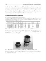
Fig. 1. Noise-tolerant impulse recognition automaton of length 8
4.2 Incremental measurement for flow control
The volume measurement and flow control represent the main functions of the hazardous
states. The next applied application pattern, incremental measurement, means the
recognition and counting of elementary volumes represented by rectangular impulses,
which are generated by a photoelectric pulse generator. The maximal frequency of impulses
and a pattern for their recognition depend on electro-magnetic interference characteristics.
The lower-level application patterns are in this case a noise-tolerant impulse detector and a
checking reversible counter. The first one represents a clock-timed impulse-recognition
automaton that implements the periodic sampling of its input with values 0 and 1. This
automaton with b states recognizes an impulse after b/2 (b>=4) samples with the value 1
followed by b/2 samples with the value 0, possibly interleaved by induced error values, see
an example timed-state sequence:
(0, q
1
)
inp=0
→
inp=0
→ (i, q
1
)
inp=1
→ (i+1, q
2
)
inp=0
→
inp=0
→ (j, q
2
)
inp=1
→ (k, q
b/2+1
)
inp=1
→
inp=1
→ (m, q
b-1
)
inp=0
→ (m+1, q
b
)
inp=1
→
inp=1
→ (n, q
b
)
inp=0/IMP
→ (n+1, q
1
)
i, j, k, m, n are integers representing discrete time instances in increasing order.
For the sake of fault-detection requirements, the incremental detector and transfer path are
doubled. Consequently, the second, identical noise-tolerant impulse detector appears
necessary.
The subsequent lower-level application pattern used provides a checking reversible counter,
which starts with the value (h + l)/2 and increments or decrements that value according to
Frontiers in Robotics, Automation and Control
156
the "impulse detected" outputs from the first or the second recognition automaton. Overflow
or underflow of the pre-set values of h or l indicates an error. Another counter that counts
the recognized impulses from one of the recognition automata maintains the whole
measured volume. The output of the letter automaton refines to two displays with local
memories not only for the reason of robustness (they can be compared) but also for
functional requirements (double-face stand). To guarantee the overall fault detection
capability of the device, it is necessary also to consider checking the counter. This task can be
maintained by an I/O watchdog application pattern that can compare input impulses from
the photoelectric pulse generator and the changes of the total value; evidently, the
appropriate automaton provides again reversible counting.
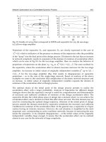
The noise-tolerant impulse detector was identified as a reusable design-pattern and its
abstract specification written using TLA+ can be stored in a case library. This specification is
shown in Fig. 2. The actions Count1 and Count0 capture the behaviour of the automaton at
sampling times. Action Restart defines an output of the automaton, which is to pose the
signal on impuls output as the signalization of successful impulse detection.
Fig. 2.Abstract TLA specification of noise-tolerant impulse recognition automaton
4.3 Fault Maintenance Concepts
The methods used a ccomplish the fault management in the form of (a) hazardous state
Pattern-driven Reuse of Behavioral Specifications in Embedded Control System Design
157
reachability control and (b) hazardous state maintenance. In safe states, the lift cabins are
fixed at any floors. The system is allowed to reach any hazardous state when all relevant
processors successfully passed the start-up checks of inputs and monitored outputs and of
appropriate communication status. The hazardous state maintenance includes operational
checks and, for shaft controller, the fail-stop support by two watchdog processors
performing consistency checking for both execution processors. To comply with safety-
critical conception, all critical inputs and monitored outputs are doubled and compared;
when the relevant signals differ, the respective lift is either forced (in case of need with the
help of an substitute drive if the shaft controller is disconnected) to reach the nearest floor
and to stay blocked, or (in the case of maintenance or fire brigade support) its services are
partially restricted. The basic safety hard core includes mechanical, emergency brakes.
Because permanent blocking or too frequently repeated blocking is inappropriate, the final
implementation must employ also fault avoidance techniques. The other reason for the fault
avoidance application stems from the fact that only approximated fail-stop implementation
is possible. Moreover, the above described configurations create only skeleton carrying
common fault-tolerant techniques see e.g. (Maxion et al., 1987). In short, while auxiliary
hardware components maintain supply-voltage levels, input signals filtering, and timing,
the software techniques, namely time redundancy or skip-frame strategy, deal with non-
critical inputs and outputs.
5. Multiple Lift Control System
The second case study deals with the multiple lift control system based on a dedicated
multiprocessor architecture (for more details see Sveda, 1997). An incremental measurement
device for position evaluation, and position and speed control of a lift cabin in a lift shaft can
demonstrate reusability. The applied application pattern, incremental measurement, means
in this case the recognition and counting of rectangular impulses that are generated by an
electromagnetic or photoelectric sensor/impulse generator, which is fixed on the bottom of
the lift cabin and which passes equidistant position marks while moving along the shaft.
That device communicates with its environment through interfaces with impulse generator
and drive controller. So, the first input, I, provides the values 0 or 1 that are altered with
frequency equivalent to the cabin speed. The second input, D, provides the values "up,"
"down," or "idle." The output, P, provides the actual absolute position of the cabin in the
shaft.
5.1 Two-level structure for lift control
The next employed application pattern is the two-level structure: the higher level behaves as
an event-driven component, which behavior is roughly described by the state sequence
initialization → position_indication → fault_indication
and the lower level, which behaves as a set of real-time interconnected components. The
specification of the lower level can be developed by refining the higher level state
"position_indication" into three communicating lower level automata: two noise-tolerant
impulse detectors and one checking reversible counter.
Frontiers in Robotics, Automation and Control
158
5.2 Incremental measurement for position and speed control
Intuitively, the first automaton models the noise-tolerant impulse detector in the same
manner as in previous case, see the following timed-state sequence:
(0, q
1
)
inp=0
→
inp=0
→ (i, q
1
)
inp=1
→ (i+1, q
2
)
inp=0
→
inp=0
→ (j, q
2
)
inp=1
→ (k, q
b/2+1
)
inp=1
→
inp=1
→ (m, q
b-1
)
inp=0
→ (m+1, q
b
)
inp=1
→
inp=1
→ (n, q
b
)
inp=0/IMP
→ (n+1, q
1
)
i, j, k, m, n are integers representing discrete time instances in increasing order.
The information about a detected impulse is sent to the counting automaton that can also
access the indication of the cabin movement direction through the input D. For the sake of
fault-detection requirements, the impulse generator and the impulse transfer path are
doubled. Consequently, a second, identical noise-tolerant impulse detector appears
necessary. The subsequent application pattern is the checking reversible counter, which
starts with the value (h + l)/2 and increments or decrements the value according to the
“impulse detected” outputs from the first or second recognition automaton. Overflow or
underflow of the preset values of h or l indicates an error. This detection process sends a
message about a detected impulse and the current direction to the counting automaton,
which maintains the actual position in the shaft. To check the counter, an I/O watchdog
application pattern employs again a reversible counter that can compare the impulses from
the sensor/impulse generator and the changes of the total value.
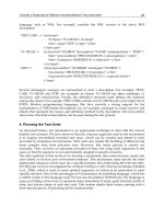
The reuse of the noise-tolerant impulse detector is desirable. To do this, suitable patterns
stored in a case library need to be identified. The method for identification of candidate
patterns is based on the behavioural similarity by means of inclusion of a state sequence in
models of stored specifications. The TLA tools can be used for formal checking whether a
design pattern stored in a case library contains a state sequence that describes the new
design. The new TLA module Query (see Fig. 3) is generated for the purpose of checking
whether the design pattern from the previous case study can be reused in the multiple lift
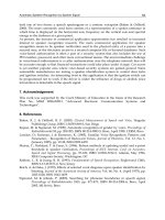
control system. Note that the formula is negated in order to get an example of concrete state-
sequence in a model of matched specification. The state-sequence is shown in Fig. 4. It has
25 unique states and describes the behaviour that conforms to the required state-sequence
defining the intended behaviour of noise-tolerant impulse detector for lift control system. In
the reuse scenario, the required size of the new automaton is 4. The stored design pattern in
a case library can be parameterized; hence the model-checking procedure instantiates the
constant B = 4, which is defined in the accompanying configuration file.
Fig. 3. TLA Module Query containing sought-after timed-state sequence
Pattern-driven Reuse of Behavioral Specifications in Embedded Control System Design
159
Fig. 4. A trace found by the TLC for state-sequence specified in Query module
5.3 Lift fault management
The approach used accomplishes a consequent application pattern, fault management based
on fail-stop behavior approximations, both in the form of (a) hazardous state reachability
control and (b) hazardous state maintenance. In safe states, the lift cabins are fixed at any
floors. The system is allowed to reach any hazardous state when all relevant processors have
successfully passed the start-up checks of inputs and monitored outputs and of appropriate
communication status. The hazardous state maintenance includes operational checks and
consistency checking for execution processors. To comply with safety-critical conception, all
critical inputs and monitored outputs are doubled and compared. When the relevant signals
differ, the respective lift is either forced (with the help of a substitute drive if the shaft
controller is disconnected) to reach the nearest floor and to stay blocked.
The basic safety hard core includes mechanical, emergency brakes. Again, more detailed
specification should reflect not only safety but also functionality with fault-tolerance
support: also blocked lift is safe but useless. Hence, the above described configurations
create only skeleton carrying common fault-tolerant techniques.
Frontiers in Robotics, Automation and Control
160
6. Application Patterns Reuse
The two case studies presented above demonstrate the possibility to reuse effectively
substantial parts of the design dealing with petrol pumping station technology for a lift
control technology project. While both cases belong to embedded control systems, their
application domains and their technology principles differ: volume measurement and
dosage control seems not too close to position measurement and control. Evidently, the
similarity is observable by employment of application patterns hierarchy, see Table 1.
fault management based on fail-stop behavior approximations
two-level (event-driven/real-time) structure
incremental measurement
noise-tolerant impulse detector checking reversible counter /O watchdog
Table 1. Application patterns hierarchy.
The reused upper-layer application patterns presented include the automata-based
descriptions of incremental measurement, two-level (event-driven/real-time) structure, and
fault management stemming from fail-stop behavior approximations. The reused lower-
layer application patterns are exemplified by the automata-based descriptions of noise-
tolerant impulse detector, checking reversible counter, and I/O watchdog.
Clearly, while all introduced application patterns correspond to design patterns in the
above-explained interpretation, the upper-layer application patterns can be related also to
frameworks. Moreover, the presented collection of application patterns creates a base for a
pattern language supporting reuse-oriented design process for real-time embedded systems.
7. Knowledge-Based Support
Industrial scale reusability requires a knowledge-based support, e.g. by case-based
reasoning (see Kolodner, 1993), which differs from other rather traditional methods of
Artificial Intelligence relying on case history. For a new problem, the case-based reasoning
strives for a similar old solution. This old solution is chosen according to the correspondence
of a new problem to some old problem that was successfully solved by this approach.
Hence, previous significant cases are gathered and saved in a case library. Case-based
reasoning stems from remembering a similar situation that worked in past. For software
reuse, case-based reasoning utilization has been studied from several viewpoints as
discussed e.g. by Henninger (1998), and by Soundarajan and Fridella (1998).
7.1 Case-Based Reasoning
The case-based reasoning method contains (1) elicitation, which means collecting those
cases, and (2) implementation, which represents identification of important features for the
case description consisting of values of those features. A case-based reasoning system can
only be as good as its case library: only successful and sensibly selected old cases should be
Pattern-driven Reuse of Behavioral Specifications in Embedded Control System Design
161
stored in the case library. The description of a case should comprise the corresponding
problem, solution of the problem, and any other information describing the context for
which the solution can be reused. A feature-oriented approach is usually used for the case
description.
Case library serves as the knowledge base of a case-based reasoning system. The system
acquires knowledge from old cases while learning can be achieved accumulating new cases.
While solving a new case, the most similar old case is retrieved from the case library. The
suggested solution of the new case is generated in conformity with this retrieved old case.
Search for the similar old case from the case library represents important operation of case-
based reasoning paradigm.
7.2 Backing Techniques
Case-based reasoning relies on the idea that situations are mostly repeating during the life
cycle of an applied system. Further, after some period, the most frequent situations can be
identified and documented in the case library. So, the case library can usually cover
common situations. However, it is impossible to start with case-based reasoning from the
very beginning with an empty case library.
When relying on the case-based reasoning exclusively, also the opposite problem can be
encountered: after some period the case library can become huge and very semi-redundant.
Majority of registered cases represents clusters of very similar situations. Despite careful
evaluation of cases before saving them in the case library, it is difficult to avoid this
problem.
In an effort to solve these two problems, the case-base reasoning can be combined with some
other paradigm to compensate these insufficiencies. Some level of rule-based support can
partially cover these gaps with the help of rule-oriented knowledge; see (Sveda, Babka and
Freeburn 1997). Rule-based reasoning should augment the case-based reasoning in the
following situations:
• No suitable old solution can be found for a current situation in the case library and
engineer hesitates about his own solution. So, rule-based module is activated. For a
very restricted class of tasks, the rule-based module is capable to suggest its own
solution. Once generated by this part of the framework, such a solution is then
evaluated and tested more carefully. However, if the evaluation is positive, this
case is later saved in the case library covering one of the gaps of the case-based
module.
• Situations are similar but rarely identical. To fit closer the real situation, adaptation
of the retrieved case is needed. The process of adaptation can be controlled by the
rule-based paradigm, using adaptation procedures and heuristics in the form of
implication. Sensibly chosen meta-rules can substantially improve the effectiveness
of the system.
The problem of adaptation is quite serious when a cluster of similar cases is replaced by one
representative only - to avoid a high level of redundancy of the case library. The level of
similarity can be low for marginal cases of the cluster. So, adaptation is more important
here.
Three main categories of rules can be found in the rule-based module:
Frontiers in Robotics, Automation and Control
162
• Several general heuristics can contribute to the optimal solution search of a very
wide class of tasks.
• However, the dominant part of the knowledge support is based on a domain-
specific rule.
• For a higher efficiency, metarules are also attached to the module. This “knowledge
about knowledge” can considerably contribute to a smooth reasoning process.
While involvement of an expert is relatively low for case-based reasoning module, the rules
are mainly based on expert’s knowledge. However, some pieces of knowledge can also be
obtained by data mining.
7.3 Similarity measurement of state-based specifications
Retrieval schemes proposed in the literature can be classed based upon the technique used
to index cases during the search process (Atkinson, 1998): (a) classification-based schemes,
which include keyword or feature-based controlled vocabularies; (b) structural schemes,
which include signature or structural characteristics matching; and (c) behavioral schemes;
which seek relevant cases by comparing input and output spaces of components.
The problem to be solved arises how to measure the similarity of state-based specifications
for retrieval. Incidentally, similarity measurements for relational specifications have been
resolved by Jilani, et al. (2001). The primary approach to the current application includes
some equivalents of abstract data type signatures, belonging to structural schemes, and
keywords, belonging to classification schemes. While the first alternative means for this
purpose to quantify the similarity by the topological characteristics of associated finite
automata state-transition graphs, such as number and placement of loops, the second one is
based on a properly selected set of keywords with subsets identifying individual patterns.
The current research task of our group focuses on experiments enabling to compare those
alternatives.
8. Conclusions
The book chapter stems from the paper (Sveda, Vrba and Rysavy, 2007) and complements it
by TLA specifications. The original contribution consists in proposal how to represent a
system’s formal specification as an application pattern structure of specification fragments.
Next contribution deals with the approach how to measure similarity of formal
specifications for retrieval in frame of case-based reasoning support. The above-presented
case studies, which demonstrate the possibility to effectively reuse concrete application
pattern structures, have been excerpted from two realized design cases.
The application patterns, originally introduced as “configurations” in the design project of
petrol pumping station control technology based on multiple microcontrollers (Sveda, 1996),
were effectively but without any dedicated development support reused for the project
of lift control technology (Sveda, 1997). The notion of application pattern appeared for the
first time in (Sveda, 2000) and was developed in (Sveda, 2006). By the way, the first
experience of the authors with case-based reasoning support to knowledge preserving
Pattern-driven Reuse of Behavioral Specifications in Embedded Control System Design
163
development of an industrial application was published in (Sveda, Babka and Freeburn,
1997).
8. Acknowledgements
The research has been supported by the Czech Ministry of Education in the frame of
Research Intentions MSM 0021630528: Security-Oriented Research in Information
Technology
and MSM 0021630503 MIKROSYN: New Trends in Microelectronic Systems and
Nanotechnologies, and by the Grant Agency of the Czech Republic through the grants
GACR 102/08/1429: Safety and Security of Networked Embedded System Applications and
GACR 201/07/P544: Framework for the deductive analysis of embedded software.
10. References
Alexander, C. (1977) A Pattern Language: Towns / Buildings / Construction, Oxford
University Press.
Alur, R. and T.A. Henzinger (1992) Logics and Models of Real Time: A Survey. In: (de
Bakker, J.W., et al.) Real-Time: Theory in Practice. Springer-Verlag, LNCS 600, 74-
106.
Arora, A. and S.S. Kulkarni (1998) Component Based Design of Multitolerant Systems. IEEE
Transactions on Software Engineering, 24(1), 63-78.
Atkinson, S. (1998) Modeling Formal Integrated Component Retrieval. Proceedings of the
Fifth International Conference on Software Reuse, IEEE Computer Society, Los
Alamitos, California, 337-346.
Coad, P. and E.E. Yourdon (1990) Object-Oriented Analysis, Yourdon Press, New York.
Frakes, W.B. and K. Kang (2005) Software Reuse Research: Status and Future. IEEE
Transactions on Software Engineering, 31(7), 529-536.
Gamma, E., R. Helm, R. Johnson and J. Vlissides (1995) Design Patterns Elements of
Reusable Object-Oriented Software, Addison-Wesley.
Geppert, B. and F. Roessler (2001) The SDL Pattern Approach – A Reuse-driven SDL Design
Methodology. Computer Networks, 35(6), Elsevier, 627-645.
Henninger, S. (1997) An Evolutionary Approach to Constructing Effective Software Reuse
Repositories. Transactions on Software Engineering and Methodology, 6(2), 111-
140.
Henninger, S. (1998) An Environment for Reusing Software Processes. Proceedings of the
Fifth International Conference on Software Reuse, IEEE Computer Society, Los
Alamitos, California, 103-112.
Holtzblatt, L.J., R.L. Piazza, H.B. Reubenstein, S.N. Roberts and D.R. Harris (1997) Design
Recovery for Distributed Systems. IEEE Transactions on Software Engineering,
23(7), 461-472.
Jacobson, L. (1992) Object-Oriented Software Engineering: A User Case-Driven Approach,
ACM Press.
Jilani, L.L., J. Deshamais and A. Mili (2001) Defining and Applying Measures of Distance
Between Specifications. IEEE Transactions on Software Engineering, 27(8), 673-703.
Johnson, R.E. (1997) Frameworks = (Components + Patterns), Communications of the ACM,
40(10), 39 42.
Frontiers in Robotics, Automation and Control
164
Kolodner, J. (1993) Case-based Reasoning, Morgan Kaufmann, San Mateo, CA, USA.
Lamport, L. (1994) Temporal Logic of Actions. ACM Transactions on Programming
Languages and Systems, 16(3) :872-923.
Lamport, L. (2002) Specifying Systems. Addison-Wesley, 2002.
Mili, R., A. Mili, and R.T. Mittermeir (1997) Storing and Retrieving Software Components: A
Refinement Based System. IEEE Transactions on Software Engineering, 23(7), 445-
460.
Sen, A. (1997) The Role of Opportunity in the Software Reuse Process. IEEE Transactions on
Software Engineering, 23(7), 418-436.
Shaw, M. and D. Garlan (1996) Software Architecture, Prentice Hall.
Soundarajan, N. and S. Fridella (1998) Inheritance: From Code Reuse to Reasoning Reuse.
Proceedings of the Fifth International Conference on Software Reuse, IEEE
Computer Society, Los Alamitos, California, 206-215.
Sutcliffe, A. and N. Maiden (1998) The Domain Theory for Requirements Engineering. IEEE
Transactions on Software Engineering, 24(3), 174-196.
Sveda, M. (1996) Embedded System Design: A Case Study. IEEE Proc. of International
Conference and Workshop ECBS'96, IEEE Computer Society, Los Alamitos,
California, 260-267.
Sveda, M., O. Babka and J. Freeburn (1997) Knowledge Preserving Development: A Case
Study. IEEE Proc. of International Conference and Workshop ECBS'97, Monterey,
California, IEEE Computer Society, Los Alamitos, California, 347-352.
Sveda, M. (1997) An Approach to Safety-Critical Systems Design. In: (Pichler, F., Moreno-
Diaz, R.) Computer Aided Systems Theory, Springer-Verlag, LNCS 1333, 34-49.
Sveda, M. (2000) Patterns for Embedded Systems Design. In: (Pichler, F., Moreno-Diaz, R.,
Kopacek, P.) Computer Aided Systems Theory EUROCAST'99, Springer-Verlag,
LNCS 1798, 80-89.
Sveda, M. and R. Vrba (2006) Fault Maintenance in Embedded Systems Applications.
Proceedings of the Engineering of Computer-Based Systems. Proceedings of the
Third International Conference on Informatics in Control, Automation and
Robotics (ICINCO 2006), INSTICC, Setúbal, Portugal, 183-186.
Sveda, M., R. Vrba and O. Rysavy (2007) Pattern-Driven Reuse of Embedded Control Design
Behavioral and Architectural Specifications in Embedded Control System
Designs. Proceedings of Fourth International Conference on Informatics in Control,
Automation and Robotics (ICINCO 2007), INSTICC, Angers, FR, pp. 244-248.
Turner, K.J. (1997) Relating Architecture and Specification. Computer Networks and ISDN
Systems, 29(4), 437-456.
van Lamsweerde, A. and L. Willemet (1998) Inferring Declarative Requirements
Specifications from Operational Scenarios. IEEE Transactions on Software
Engineering, 24(12), 1089-1114.
Xinyao, Y., W. Ji, Z. Chaochen and P.K. Pandya (1994) Formal Design of Hybrid Systems. In:
(Langmaack, H., W.P. de Roever and J. Vytopil) Formal Techniques in Real-Time
and Fault-Tolerant Systems, Springer-Verlag, LNCS 863, 738-755.
Zaremski, A.M. and J.M. Wing (1997) Specification Matching of Software Components.
ACM Trans. on Software Engineering and Methodology, 6(4), 333-369.
10
Optical Speed Measurement and applications
Tibor Takács, Viktor Kálmán, dr. László Vajta
Budapest University of Technology and Economics
Department of Control Engineering and Information Technology
Hungary
1. Introduction
Mobile robot navigation is a well researched discipline, looking back to a relatively long
history however it is still a rich, active area for research and development. The ultimate goal
for robots and intelligent vehicles seems to be autonomous navigation in complex real life
scenarios. In order to achieve higher levels of autonomy sophisticated sensors and a sound
understanding of the robot and its interaction with the environment is needed. The tasks
involved can be divided to two basic categories; internal tasks involve keeping track of
internal dynamic parameters, like speed accelerations, internal states etc. On the other hand
the vehicle needs to be aware of external factors like obstacles, points of interest, possible
routes from a to b and the respective costs. This is generally called robotic mapping.
Intelligent Vehicle stands for a vehicle that senses the environment and provides
information or control to assist the driver in optimal vehicle operation. Intelligent Vehicle
systems operate at the tactical level of driving (throttle, brakes, steering) as contrasted with
strategic decisions such as route choice, which might be supported by an on-board
navigation system. (Bishop, 2005)
Optical sensors supply by far the most information and as greater and greater processing
capabilities become readily available their use becomes more widespread. Many researchers
and companies have made more or less successful attempts at creating optical sensors for
speed measurement, however to the knowledge of the authors no accurate high speed
solution exist at the low price range. The aim of this article is to introduce a novel method
for optical speed measurement and put it into perspective by summarizing other navigation
methods and reviewing recent related work and possible applications. Also an introduction
to optical flow calculation is given and practical considerations on texture analysis and
sensor parameters are discussed backed up with simulation results.
2. Motion measurement techniques
The development of navigation and dynamic sensors has always had a prominent place in
mobile robotics research, as the key to accurate trajectory tracking and precise movements is
the exact knowledge of the dynamic parameters of the mobile platform.
Frontiers in Robotics, Automation and Control
166
2.1 Incremental techniques
The first class of movement measurement methods - called incremental techniques - uses
only sensors located on the mobile platform. In this case the actual position is calculated
from the previous pose-information and the relative displacement measured by the motion-
sensors. This navigation mode is often called “dead reckoning navigation”.
On wheeled vehicles the most straightforward method is to measure wheel movements and
calculate displacement accordingly. Rotations can be measured with optical encoders,
proximity sensors and cog wheels or magnetic stripes with Hall sensors etc. Heading
information can be derived from differential odometry, which means calculating the
direction based on the distance difference travelled by the left side and right side wheels of
the vehicle. In addition to optical encoders, potentiometers, synchros, resolvers and other
sensors capable of measuring rotation can be used as odometry sensors. In the last few years
in the wake of the invention of the optical mouse optical navigation found its way to mobile
robotics, and other similar methods emerged in the transportation industry.
(Borenstein et al. 1996) describes thoroughly the various aspects related to odometry
including typical error sources. Many of the systematic errors come from the errors of the
kinematical model (wheelbase, wheel radius, misalignment etc.), some depend on the
electronics (finite sampling rate, resolution). Non systematic errors occur when the wheel
slips due to uneven surface or overacceleration etc. Some of these problems can be
eliminated by the use of inertial methods, when accelerations and rotations are measured in
three dimensions and integrated over time to derive position, speed and heading
information. These methods are very sensitive to sensor quality since the double integration
in position determination is prone to drift. (Mäkelä 2001) Due to accumulated errors
measurements loose accuracy over time therefore position and speed information is usually
periodically updated from an absolute source.
2.2 Absolute methods
In this case the actual position can be calculated without any previous information about the
motion of the agent. The global pose is estimated directly (with one measurement) by means
of external – artificial or natural – beacons which are totally independent from the platform.
Artificial beacons are objects which are placed at known positions with the main purpose of
being used for pose determination. According to this definition, setting up the working
environment for a robot using artificial beacons almost always requires a considerable
amount of building and maintenance work. In addition, using active beacons requires a
power source to be available for each beacon. GPS positioning is one of the major exceptions
since the system is almost constantly available for outdoor navigation. Although the
ultimate goal of research is to develop navigation systems which do not require beacons to
be installed in the working environment, artificial beacons are still preferred in many cases.
The reason is that artificial beacons can be designed to be detected very reliably which is not
always the case when using natural beacons. For pose estimation in two dimensions, one
can either measure the distances or bearings to at least three beacons and calculate the
position and the heading by simple geometry. The calculation is called trilateration if it is
based on known distances, and triangulation if it is based on bearings. Distance from the
beacons can be measured by using several different methods like triangulation, time of
flight, phase-shift measurement, frequency modulation, interferometry, swept focus, or
Optical Speed Measurement and applications
167
return signal intensity etc. The sensors used can be radio or laser based ultrasonic, or visual.
The advantage of artificial beacon based systems is that they can be made very accurate as
the environment is controlled, however this same controlled environment is the biggest
disadvantage as it decreases flexibility. In certain cases system complexity becomes a
problem, as was the case with GPS before mass production of receiver chips started.
Artificial beacons are relatively simple to use and pose estimation based on them is
straightforward and reliable. However, there are various applications where they can not be
used. Natural beacons are objects or features of the environment of the robot that can be
used for pose estimation. These beacons can be man made; natural means they were not
built for navigation purposes. Navigation using a map is also related to natural beacons,
when the map is matched to raw sensor data the whole environment can be considered as a
beacon. (Mäkelä 2001)
2.3 Fusion
Through sensor fusion we may combine readings from different sensors, remove
inconsistencies and combine the information into one coherent structure. This kind of
processing is a fundamental feature of all animal and human navigation, where multiple
information sources such as vision, hearing and balance are combined to determine position
and plan a path to a goal. While the concept of data fusion is not new, the emergence of new
sensors, advanced processing techniques, and improved processing hardware make real-
time fusion of data increasingly possible (Bak 2000).
Incremental and absolute navigation techniques have somewhat complementing advantages
and disadvantages so developers usually combine them to benefit from the advantages of
both. In case of absolute techniques like for example GPS, the navigation system can directly
calculate the absolute position of the platform therefore the error of the actual pose comes
only from the current measurement and does not accumulate over time. But unfortunately
in some cases these methods are unusable for direct positioning or speed measurement, for
lack of signal or unacceptable latency. Incremental techniques are usually simpler and have
greater data rates, but accumulate error over time.
In addition the ability of one isolated device to provide accurate reliable data of its
environment is extremely limited as the environment is usually not very well defined in
addition to sensors generally not being a very reliable interface. Sensor fusion seeks to
overcome the drawbacks of current sensor technology by combining information from many
independent sources of limited accuracy and reliability to give information of better quality.
This makes the system less vulnerable to failures of a single component and generally
provides more accurate information. In addition several readings from the same sensor are
combined, making the system less sensitive to noise and anomalous observations.
Basically motivations for sensor fusion can be categorized into three groups (Bak 2000).
Complementary. Sensors are complementary when they do not depend on each other
directly, but can be combined to give a more complete image of the environment.
Competitive. Sensors are competitive when they provide independent measurements of the
same information. They provide increased reliability and accuracy. Because competitive
sensors are redundant, inconsistencies may arise between sensor readings, and care must be
taken to combine the data in a way that removes the uncertainties. When done properly, this
kind of data fusion increases the robustness of the system.