InTech-Climbing and walking robots towards new applications Part 6 pot
Bạn đang xem bản rút gọn của tài liệu. Xem và tải ngay bản đầy đủ của tài liệu tại đây (455.51 KB, 30 trang )
Climbing & Walking Robots, Towards New Applications
150
The ACFM NDT results are the work of TWI Ltd, Cambridge (UK) and the results from
experiments on ultrasonic radar are the work of Isotest Engineering, Italy.
The work on RobTank Inspec was funded by the European Community through the FP6
programme (Competitive and sustainable growth). Project coordinator was ISQ Ltd
(Portugal). Partners: Tecnatom (Spain), Phoenix Inspection Systems (UK), OIS (UK), London
South Bank University (UK), Petrogal (Portugal).
6. References
Berger A., Knape B., Thompson B. (1990) Development of a Remote Tank Inspection (RTI)
Robotic System, Proceedings of 1990 American Nuclear Society Winter
Meeting,Washington D.C., November 1990
European CRAFT project FPSO-INSPECT, Non-Intrusive In-Service Inspection Robot for
Condition Monitoring of Welds Inside Floating Production Storage and Off-loading
(FPSO) Vessels, EU 6th Framework Programme, Co-operative Research Project,
COOP-CT-2004-508599, December 2004.
King R.D., Raebiger, R.F., Friess R.A. (1992) Consolidated-Edison-Company-Of-New-York,
Inc - Petroleum Fuel-Oil Tank Inspection Program, Proceedings of the American
Power Conference, Chicago, Illinois, Vol 54, Pt 1 and 2 Moving Ahead While
Protecting the Environment, pg. 983-988
Raad J.A. (1994) Techniques for Storage Tank Inspection, Materials Evaluation, July 1994,
pg 806-7
Rusing, J.E. (1994) The NDT Perspective on Above Ground Storage Tanks, Materials
Evaluation, July 1994, pg 801-804
(a) Sattar T.P., Leon-Rodriguez H., Shang J., (2005) Automated NDT Of Floating Production
Storage Oil Tanks With A Swimming And Climbing Robot, in Proceedings of the
8th International Conference on Climbing and Walking Robots and the Support
Technologies for Mobile Machines (CLAWAR 2005), Editors Tokhi, Virk and
Hossain, ISBN-10 3-540-26413-2, Springer, ISBN-13 978-3-540-26413-2, pp. 935-942
(b) Sattar T.P., Zhao Z., Feng J., Bridge B., Mondal S., Chen S., (2002) Internal In-service
Inspection of the floor and walls of Oil, Petroleum and Chemical Storage Tanks
with a Mobile Robot, Proceedings Of 5th International Conference on Climbing and
Walking Robots and the Support Technologies for Mobile Machines, Edited by
Philipe Bidaud and Faiz Ben Amar, ISBN 1 86058 380 6, 2002, pp 947-954,
Professional Engineering Publishing Ltd. UK
Schempf H. (1994). Neptune-Above-Ground Storage Inspection Robot System, Proceeding
of IEEE International Conference on Robotics and Automation, San Diego, Vols 1-4,
Part 2. pg. 1403-1408
Shang, J., Sattar, T.P., Leon Rodriguez , H.E, (2006) PDA Depth Control of a FPSO
Swimming Robot, Proceedings of the 9th International Conference on Climbing
and Walking Robots and the Support Technologies for Mobile Machines (CLAWAR
2006)
Shimamura Y. (2002) FPSO/FSO: State of the art, J. Mat. Sci. Technol. 2002, pp 60-70.
7
Test Methods and Knowledge Representation
for Urban Search and Rescue Robots
Craig Schlenoff, Elena Messina, Alan Lytle, Brian Weiss and Ann Virts
National Institute of Standards and Technology (NIST)
USA
1. Introduction
Urban Search and Rescue (USAR) is defined as “the strategy, tactics, and operations for
locating, providing medical treatment, and extrication of entrapped victims.” (Federal
Emergency Management Agency 2000) USAR teams exist at national, state, and local
levels. At the national level, the Federal Emergency Management Agency (FEMA), which
is part of the Department of Homeland Security, has Task Forces that respond to major
disasters. There are many challenges in diverse disciplines entailed in applying robots for
USAR. Examples include range and penetration limitations for wireless radio signals that
send commands to the robots from the operator control station, the ability of the platforms
to withstand moisture, dust, and other contaminants, and the resolution of onboard
navigation cameras.
NIST is working with FEMA Task Force members to define performance requirements and
standard test methods as well as to assess the deployment potential of robots applied to the
USAR domain. The development process being employed during this effort is driven by
user-defined requirements, which were initially articulated by FEMA responders during an
initial set of workshops hosted by NIST. Responders also identified different deployment
categories for robots within USAR missions. These deployment categories describe types of
capabilities or features the robots should have, along with tradeoffs. Thirteen different
categories were defined, which may not necessarily map to thirteen different robot types
(i.e., a particular robot may serve within more than one category).
Supporting efforts are detailing robot capabilities and deployment environments in
unambiguous computer-usable formats. An ontology is being used as the neutral
representation format for the robot characteristics. A complementary effort is attempting to
quantify and characterize the environment into which the robots will be deployed.
Taxonomies of buildings (pre and post-collapse) are being developed, as well as methods of
deriving mathematical representations of the surfaces which the robots must cross. This
chapter discusses all of these efforts in depth, as they are key enablers in the quest to match
robot capabilities to the deployment environments.
O
pen Access Database www.i-techonline.co
m
Source: Climbing & Walking Robots, Towards New Applications, Book edited by Houxiang Zhang,
ISBN 978-3-902613-16-5, pp.546, October 2007, Itech Education and Publishing, Vienna, Austria
152 Climbing & Walking Robots, Towards New Applications
Several requirements for robots applied to USAR involve mobility capabilities. Aerial,
ground, and aquatic robots can all play a part in USAR operations and have unique mobility
challenges and requirements. It is clear, however, that the usefulness of robots in USAR is
highly dependent on their mobility capabilities as they must be able to negotiate highly
unstructured environments. This chapter will highlight aspects of mobility that are relevant
to robots that can walk or climb. The chapter is structured as follows. Section 2 describes
the initial requirements-gathering phase for this project and details the requirements that
were produced. This is followed by a discussion in Section 3 of the test method
development and standardization approach, including descriptions of some of the more
fully-developed test methods. Section 4 discusses the tools and techniques that have been
created to capture performance data as robots are tested. Response robot exercises are
described in Section 5. Section 6 covers the knowledge representation efforts, including the
robot specifications and ontology and the structural collapse taxonomy. Conclusions are
presented in Section 7.
2. Defining the Performance Requirements for USAR Robots
Although the potential for utilizing robots to assist rescuers in USAR operations was
recognized prior to this project’s inception, a methodical capture of responders’ views of
how they would use robots and what the detailed performance requirements were for
robots had not occurred previously. Beginning in Fall 2004, NIST worked closely with DHS
Science and Technology and FEMA to initiate a series of workshops that defined the initial
set of performance requirements for robots applied to USAR. The first three workshops
deliberately did not include robot technologists and vendors, so as to not initially bias the
input from the end users with knowledge of existing technologies or approaches. Once a
substantial body of requirements was gathered from responders, in subsequent workshops,
robot technology providers (researchers, vendors, other government programs) were
encouraged to participate.
The requirements definition process during the initial set of workshops was comprised of
identifying and describing individual requirements, defining how a robot’s performance
with respect to a given requirement is to be measured, and, where possible, specifying the
objective (desired) and threshold (minimum or maximum) performance values. The
resulting list of requirements totaled over 100. These were grouped into several broad
major categories. One major category, ‘System’, was further decomposed into sub-
categories. These categories as well as the other major categories are shown in Table 1. A
draft report detailing the process, the initial set of requirements, and the robot deployment
categories is found at the NIST web site (Messina et.al. 2005).
Test Methods and Knowledge Representation for Urban Search and Rescue Robots 153
Human-System
Interaction
Pertaining to the human interaction and
operator(s) control of the robot
Logistics Related to the overall deployment procedures
and constraints in place for disaster response
Operating
Environment
Surroundings and conditions in which the
operator and robot will have to operate
Safety Pertaining to the safety of humans and
potentially property in the vicinity of the robots
System: Overall physical unit comprising the robot. This
consists of the sub-components below:
- Chassis The main body of the robot, upon which
additional components and capabilities may be
added. This is the minimum set of capabilities
(base platform).
- Communications Pertaining to the support for transmission of
information to and from the robot, including
commands for motion or control of payload,
sensors, or other components, as well as
underlying support for transmission of sensor
and other data streams back to operator
- Mobility The ability of the robot to negotiate and move
around the environment
- Payload Any additional hardware that the robot carries
and may either deploy or utilize in the course of
the mission
- Power Energy source(s) for the chassis and all other
components on board the robot
- Sensing Hardware and supporting software which sense
the environment
Table 1. Major requirements categories
Responders defined the requirements, the metrics for each, and for most of them provided
objective and threshold values. The performance objectives and thresholds are dependent
on the specific mission in some cases. For instance, the resolution of the onboard cameras
depends on the range at which objects must be observed and on the types of objects. An
aerial robot may need to provide responders information about whether a roadway ahead is
blocked or clear. Another robot, aerial or ground-based, may be required to help the
structural specialist assess the size of cracks in the structure.
As noted, there is no typical USAR scenario. FEMA teams (and other organizations) may
respond to hurricanes, explosions, or earthquakes. The buildings may be wood frame,
concrete, brick, or other construction. They may have to search subterranean, wet, confined
spaces and tunnels or they may have to climb up the sides of buildings whose facades have
154 Climbing & Walking Robots, Towards New Applications
fallen away. During the initial three requirements definition workshops, potential robot
deployment categories (which could correspond to different disaster types or aspects of a
response) were enumerated. Twelve categories were defined, which detailed the
capabilities that the robot should have, along with the deployment method, and tradeoffs.
Ground, aerial, and aquatic robot deployments are represented. The deployment categories
are listed in Table 2. In some cases, the requirements therefore need to be defined according
to mission or deployment type.
Table 2. Robot Deployment Categories
Test Methods and Knowledge Representation for Urban Search and Rescue Robots 155
Correlations were performed of the first set of requirements versus the deployment types.
Responders were asked to note which requirements applied to which deployments. The
data were analyzed to uncover which requirements affected the greatest number of
missions, hence would be the most commonly-needed. An initial set of requirements was
thus selected for conversion to test methods. After responders had opportunities to
experiment with a wide variety of different robot platforms within various scenarios and
deployments, they selected three of the twelve deployment categories as being highest
priority. This selection reflected both their opinion that these were missions in which robots
could provide the best utility and for which the robots seemed most technologically mature:
• Ground: Peek robots. Small, throwable robots that are able to be deployed into very
confined spaces and send video or potentially sensor data back to the operators.
• Aerial, Survey/Loiter Robots. These robots could “look over the hill” to assess the
situation and determine at least which roads are passable. USAR Teams don’t
necessarily expect aerial robots to assess structural integrity or even detect victims. They
would like to be able to monitor atmospheric conditions from these platforms as well.
•
Ground: Non-collapsed Structure Wide area Survey Robots. These robots could
support a downrange reconnaissance mission. They don’t necessarily have to enter
confined spaces or traverse rubble piles, but they do need to be able to climb stairs or at
least curbs and modest irregular terrain. They would typically move quickly down
range (at least 1 km) to assess the situation and deploy multiple sensors (chemical,
biological, radiological, nuclear, and explosive) with telemetry.
3. Measuring Robots Performance Against the Requirements
Among the key products of this program are standard test methods and metrics for the
various performance requirements and characteristics defined by the responders. The test
methods should be objective and clearly defined, and ideally, they will also be reproducible
by robot developers and manufacturers to provide tangible goals for system capabilities.
This will enable robot and component developers to exercise their systems in their own
locations in order to attain the required performance.
The resulting standard test methods and usage guides for USAR robots will be generated
within the ASTM International Homeland Security Committee through the E54.08
Subcommittee on Operational Equipment.
Draft test methods are evaluated several times by the responders and the robot developers
to ensure that both communities find them representative and fair. Test methods measure
performance against a specific requirement or set of requirements. The complementary
usage guides help interpret the test method results for a given type of mission or
deployment.
In this section, we will discuss the test methods to assess visual acuity, field of view, and
maneuverability over uneven terrain, pitch/roll surfaces, ramps, stairs, and confined spaces.
To illustrate the effect of different deployment categories on the performance requirements,
we will start by discussing the visual acuity and field of view test method. This test method
156 Climbing & Walking Robots, Towards New Applications
assesses performance to address the responders’ requirements listed in Table 3. The
specifics of the test set up were designed to address specifically the three types of robot
deployments selected as highest priority, noted above.
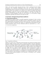
Fig. 1. Tumbling E’s
The test method utilizes the Tumbling E optotype (character) in eye charts that are to be
viewed by the operator at the control station remotely located from the robot, which is
positioned at specified distances from two eye charts (near and far). Far Vision Visual
Acuity is important for both unmanned air vehicles (UAVs) and ground vehicles for wide
area survey. Zoom is required for ground vehicles for wide area survey. Near Vision
Visual Acuity is important for ground vehicles for wide area survey in examining objects at
close range and also for small robots that operate in constrained spaces. Figure 1 shows a
sample line of tumbling E’s. The operator is to indicate which side of the letter E is open
(top, left, right, bottom) for each letter in a row. The smallest row that is correctly read in its
entirety is the one that is noted on the form. The test is conducted in both ambient light
and dark conditions (both of which are measured and noted). If the robot is traversing dark
areas (which is likely in USAR missions), onboard illumination is necessary. However, if
the illumination is not adjustable, close by objects will be “washed out” by the strong
lighting. This case will become evident if the robot illumination enables reading the far-
field chart, but precludes viewing the near-field one.
Type Sub-Type Requirement
Chassis Illumination Adjustable
Sensing Video Real time remote video
system (Near)
Sensing Video Real time remote video
system (Far)
Sensing Video Field of View
Sensing Video Pan
Sensing Video Tilt
Table 3. Requirements addressed by Visual Acuity Test Method
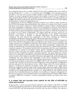
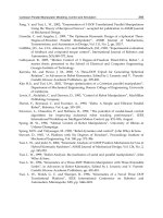
Common terrain artifacts are used in multiple test methods and are specifically aimed at
representing a world that’s not flat. They are meant to provide reproducible and repeatable
mobility or orientation challenges. Step Field Pallets (Figure 2) provide repeatable surface
topologies with different levels of “aggressiveness.” Half-cubic stepfields (referred to as
Test Methods and Knowledge Representation for Urban Search and Rescue Robots 157
“orange”) provide orientation complexity in static tests, such as Directed Perception. Full-
cubic step fields (“red”) provide repeatable surface topologies for dynamic tests, such as for
locomotion. The sizes of the steps and width of the pallets are scaleable according to the
robot sizes. Small size robots can use pallets that are made of 5 cm by 5 cm posts. Mid-
sized robots can use pallets made of 10 cm by 10 cm posts. Large-sized robots use pallets
made of clusters of four 10 cm by 10 cm posts. The topologies of the posts can be biased in
three main ways: flat, hill, and diagonal configurations. Ž
Fig. 2. Step Fields Provide Reproducible Terrain Challenges
Pitch/Roll Ramps provide non-flat flooring for orientation complexity. As implied by the
name, the orientation of the ramp can be along the direction of robot travel or perpendicular
to it. Different types of ramps are concatenated as well. The angles of the ramps can be 5°,
10°, or 15°.
In terms of how the performance is measured in these test methods, there is a wide variance
in the abilities and levels of experience of the operators. Therefore each test method’s data
capture form includes a selection of the operator’s self-declared experience level (novice,
intermediate, or expert). When the “official” data is collected for a robot (once the test
method is a standard), the robot manufacturer will supply the operator(s) that will conduct
the test. We expect to strive for statistically significant numbers of trials, so that the data is
averaged over numerous repetitions. Ideally, the performance data will include the level
of expertise and can thus be further analyzed for disparities by this particular demographic.
Basic robot speeds and maneuverability on different terrains are measured in a series of
tests. To measure basic locomotion abilities and sustained speeds, the robots are to traverse
a prescribed course. The terrain types may be paved, unpaved (including vegetated), or a
variant of abstracted, but repeatable, rubble-like terrain. The course may be a zig-zag
pattern or a figure 8 pattern. For a zig-zag course, the test proctor notes the time it takes the
robot to reach the end in one direction, and then proceed back to the origin. For a figure 8
course, the robot may be required to complete a given number of laps. A variant of these
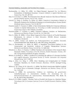
mobility tests is one that measures the ability of a robot to traverse confined spaces. In this
test, step field pallets are inverted and placed over another set of pallets (see Fig. 3). This
test measures the ability of robots to maneuver in very small spaces.
Special cases of mobility are tested using ramps and stairs. A pattern of way points is
158 Climbing & Walking Robots, Towards New Applications
marked on a ramp (at a variable angle), which the robot is to follow on an inclined plane.
Ability to do so and time to complete is noted for each angle, which is gradually increased
until the robot may no longer accomplish this safely. For robots that are able to climb walls
or move while inverted, the test can be extended to accommodate these configurations. For
the mobility on stairs, the ability of the robot to ascend and descend several flights of stairs
Fig. 3. Example Mobility Tests. Left: Confined Space Cubes; Right: Inclined Plane with
waypoint pattern
of different steepness is measured. Whether the stairs have enclosing walls or just railings,
as well as whether they have risers or are open, are among the variables.
Other test methods, not described in this chapter, measure the robot packaging volume and
weight, the situational awareness afforded by the operator control station and sensors,
aerial station-keeeping, the ability to access different spatial zones with visual and mission-
specific sensors, the ability to grasp and move objects at different locations, and wireless
communications range.
The next section describes the infrastructure that is in place to capture data during the
implementation of the test methods.
4. Data Collection – Audio/Visual
When a robot attempts a test method, performance data is captured through both
quantitative measurements and Audio/Visual (A/V) data collection. The data collected in
the former varies based upon the specific test method, while the latter is somewhat constant.
A quad video and single audio collection system is managed throughout each test method
to capture a clear representation of both the operator’s and robot’s actions during these
performance evaluations. This A/V data collection system is composed of the control and
display hub (shown in Figure 4) and supported by in-situ cameras and an operator station-
based microphone. A PC-output splash screen showing the pertinent run information
initiates the A/V collection and displays the robot name, operator’s skill level, test method,
etc. While a robot operates within a test method, video is captured of the robot from
multiple perspectives (includes a combination of ground-based and ceiling mounted
Test Methods and Knowledge Representation for Urban Search and Rescue Robots 159
cameras), the operator’s hand interactions with the robot’s control system, the robot’s visual
user interface, and the PC display output of the robot tracking system (maze test method,
only). A microphone in the operator room captures all the sounds the operator is exposed to
throughout their performance which might include audible user interface feedback or
operator comments.
Fig. 4. Quad Audio/Video Control and Display Hub
The video and audio feeds are sent into the control and display hub. While the audio
output is sent directly to the digital recording device, the video signals go through preview
monitors and switchers before the final four video outputs are fed into the quad compressor
and split out to a large display monitor and the digital recording device. Typically, the A/V
manager has more than four video sources per test method, but only has the discretion to
pick the two opportune robot video sources (displayed in the upper-right and upper-left
quadrants) while the other two video sources default to the operator’s control station
(lower-left quadrant) and robot visual user interface (lower-right quadrant).
160 Climbing & Walking Robots, Towards New Applications
5. Response Robot Exercises
The robot manufacturers and researchers and eventual end-users need to reach common
understandings of the envisioned deployment scenarios, environmental conditions, and
specific operational capabilities that are both desirable and possible for robots applied to
USAR missions. Toward that end, NIST organizes events that bring emergency responders
together with a broad variety of robots and the engineers that developed them to work
within actual responder training facilities. These informal response robot evaluation
exercises provide collaborative opportunities to experiment and practice, while refining
stated requirements and performance objectives for robots intended for search and rescue
tasks. In each instance, search scenarios are devised using facilities available at the
training facility. NIST-built simulated victims are placed within the scenarios. These may
exhibit several signs of life, including human form (typically partial), heat, sound, and
movement. Robot providers are encouraged to work closely with responders to determine
the best way to deploy robots into these scenarios. Operation of the robots by the
responders by the end of the exercise is a key goal. This enables responders to familiarize
themselves with the capabilities of the robots and to provide direct feedback to the robot
manufacturers and researchers about strengths and weaknesses of robots applied to this
domain. Three exercises have been held to date at FEMA USAR Task Force training
facilities and are briefly described in this section.
In August of 2005, the first response robot exercise for this project was held in the desert
training facility for Nevada Task Force 1. Fifteen ground (including throw-able, wall-
climbing, confined space, complex terrain reconnaissance, and other sub-categories), 3
aerial, 2 aquatic, and 2 amphibious robots participated. FEMA Task Force members from
the local team, as well as from several other areas of the country devised search scenarios
and operated robots through them. At this time, there was one nascent test method - visual
acuity - that was piloted.
The second exercise was hosted by Texas Task Force 1 at Disaster City in April 2006. (Jacoff
and Messina 2006) More than 30 robots participated in 10 scenarios at this 21 hectare facility.
The robot demographics spanned 16 models of ground vehicles, 2 models of wall climbers,
7 models of aerial vehicles including a helicopter, and 2 underwater vehicles. The scenarios
included aerial survey of a rail accident using a variety of small and micro aerial vehicles
(primarily fixed wing). Fig. 7 shows some of the scenarios. At this point, there were
several emerging test methods available to be evaluated. A standards task group meeting
was held after the exercise to gather input and test method critiques from the responders
and vendors. At a separate meeting, the responders selected the three focus robot categories
discussed above and provided an assessment of the robot maturity levels and relative
strengths and weaknesses.
Maryland Task Force 1 hosted an exercise in August 2006
.
. This event placed heavy
emphasis on evaluation of the eleven draft test methods. This exercise included 24 models
of ground robots, 2 models of wall climbers, and 2 models of aerial robots, which had to run
through all relevant test methods before proceeding to the scenarios. In addition to the
search and rescue training scenarios, there was an ad hoc experiment integrating portable
radiation sensors with robots.
Test Methods and Knowledge Representation for Urban Search and Rescue Robots 161
Collaborating with NIST researchers who are working on radiation sensor standards, sensor
vendors participated, providing sensors that were integrated with robots and deployed in a
test method (directed perception) and in a scenario. Standards working group meetings for
the communications, human-system interaction, and sensor teams were held, to capture
lessons learned during the piloting of the test methods.
After conducting four such exercises, several salient observations emerged. There are
many useful roles that robots can play in helping responders in USAR missions. In
particular, the three high priority deployment types selected by responders can fulfill useful
functions. There are some additional technological and engineering improvements still
generally needed. For instance, robots must be able to withstand very harsh conditions,
including submersion in water. Some of the robots developed for military applications are
ready to confront these challenges, but most others are not.
One current limitation present in most robots that have participated in the exercises pertains
to the wireless communications between the robot and the operator control unit (OCU).
Commands are sent from the OCU to the robot and telemetry or sensor data is sent back.
There are issues with limitations in the range for line of sight communications as well as for
non-line of sight. Responders would like to be able to send a robot a kilometer downrange
or into a collapsed concrete structure and still be able to communicate with it. Adding
autonomy to the robots, so that they may continue their mission even when out of range, or
at least return to the last location where they had radio contact would greatly increase their
robustness. Interference between robot radios and other communications equipment also is
a common problem.
Better and more sensors are desired. Responders would like better navigation aids, such as
Global Positioning System (GPS) and the ability to show the robot coordinates and direction
of view. They would like to have onboard mapping of environments when navigating
through smoke. The cameras currently used for navigation could be better-placed to afford
a higher perspective to improve path planning and obstacle avoidance. Assistance in
gauging depth is needed.
The mobility of ground robots, in general, needs improvement. There are very few
platforms that can even attempt to traverse rubble piles, such as those commonly found at
FEMA USAR training facilities. Tracks on robots (which are commonly used) can easily
come off or catch loose debris and become disabled. Stairs can foil some robots, especially
if they are dusty or otherwise slippery. A robot locomotion design based on walking, if
complemented with semi-autonomous gaits, could adapt to a wide variety of terrains and
conditions. Search dogs regularly participate at the response robot exercises, and their
ability to traverse rubble piles and other challenging terrain is unsurpassed. Wall-climbing
robots have been favorably received. Responders like the ability to peer over the tops of
buildings or use the ceiling, which may be intact, to survey a collapsed area. Figure 5 shows
examples of wall-climbers in action. The wall-climbers need to improve their robustness
and be able to deal with changes in the wall or ceiling surfaces. Discontinuities or
protuberances can cause them to lose contact with the wall and fall.
162 Climbing & Walking Robots, Towards New Applications
Fig. 5. Examples of wall-climbing robots
6. Knowledge Representation Efforts
As mentioned earlier, knowledge representation is a key enabler in the quest to match robot
capabilities to the deployment environments. With the large number of disparate robots that
are currently available, responders need an easy way to quickly determine which robot is
most appropriate for their current mission. This section describes three efforts which are
currently underway to represent robot capabilities and structural collapse types with the
goal of providing various tools to assist responders in choosing the best robot for their
mission. They are the Robot Pocket Guide, the Robot Capability Ontology, and the
Structural Collapse Taxonomy.
6.1. The Robot Pocket Guide
Over the past year, NIST has been developing a robot pocket guide to provide responders
with easy access to high-level specifications of robots. The guide is designed to fit
in a responder’s pocket and currently contains information about 28 robots that have
participated in the aforementioned exercises. Robots are classified as either ground, wall-
climbed, aquatic, or aerial. Sample pages of the pocket guide are shown in Figure 6. The
NanoMag
1
is classified as a wall climbing robot (as shown by the tab on the right).
Information that is included about the NanoMag on the left page along with a picture of the
robot and its operator control unit include its width, length, height, weight, turning
diameter, maximum speed, etc. On the right page, there is information about how the robot
performed in the test methods described earlier. Because the test methods have not yet been
1
Certain commercial software and tools are identified in this paper in order to explain our research.
Such identification does not imply recommendation or endorsement by the National Institute of
Standards and Technology, nor does it imply that the tools identified are necessarily the best
available for the purpose.
Test Methods and Knowledge Representation for Urban Search and Rescue Robots 163
finalized, all that is shown is how the information will be represented. Similar information
is included about the other 27 robots. As more robots participate in the upcoming exercises,
information about them will be added to the pocket guide.
Fig. 6. The NanoMag page in the robot pocket guide
6.2. The Robot Capability Ontology
6.2.1. Overview
The goal of this Robot Capabilities Ontology effort is to develop and begin to populate a
neutral knowledge representation (data structure) capturing relevant information about
robots and their capabilities. This ontology will help to assist in the development, testing,
and certification of effective technologies for sensing, mobility, navigation, planning,
integration and operator interaction within search and rescue robot systems. It is envisioned
that a first responder would query this knowledge representation using a graphical front
end to find robots that meet the criteria (e.g., size, weight, heat resistance, etc.) they need to
perform a desired mission in a disaster site. This knowledge representation must be flexible
164 Climbing & Walking Robots, Towards New Applications
enough to adapt as the robot requirements evolve. As such, we have chosen to use an
ontological approach for representing these requirements.
6.2.2. Sample Scenario
Passenger rail cars were hit by industrial hazmat tanker cars of unknown substance and
both trains partially derailed, as shown in Figure 7. After initial analysis, it was determined
that ground robots should circumnavigate all trains over the tracks, various debris, and
rubble. The robots should map the perimeter along with the location and positions of each
car, including under the elevated car. Robots should search the Sleeper Car ramping up
from the ground, and search each curtained alcove on both sides looking for simulated
victims. For the Crew Car on its side, robots should be inserted to explore the interior to
locate any victims or read the placards on hazardous canisters that may be in the mailroom.
Access to the mailroom is too small for a responder in Level A suit.
Fig. 7. Train Wreckage Scenarios
The first responders need to decide which robots to use out of their available cache of
robots. They go to their laptop and enter their requirements for the robots. They use pull-
down boxes and text entry boxes to state that they need a robot that can traverse rubble 15
cm (6 inches) in diameter, has sensor capabilities that can develop a 3-D map of the
environment, can withstand various hazmat conditions, and can fit into alcoves as small as
1 meter (3 feet) in width and height. They must also have sensors that can identify victims
by heat signatures. Lastly, they must have vision capabilities that read signs with 2.5 cm (1
inch) lettering from a distance of 3.2 meters (7 feet) away. Based on their requirements, two
robots are returned that are acceptable. However, one of the robots also has heat resistance
up to 90 degrees celsius (200 degrees Fahrenheit), which is not important for this scenario
but is very important for another disaster site nearby which partnering first responders are
addressing. The first responder decides to use the robot without the heat resistance and
requests that specific robot through the user interface.
6.2.3. Related Work
To the best of the authors’ knowledge, only a handful of projects exist that have addressed
the challenge of developing a knowledge representation for Urban Search and Rescue
(USAR). One such effort is being performed at the University of Electro-Communications in
Test Methods and Knowledge Representation for Urban Search and Rescue Robots 165
Tokyo, Japan (Chatterjee and Matsuno 2005). This work intends to identify the necessity and
scope of developing ontology standards for describing the rescue robot features and for
describing the disaster scenarios in the context of search and rescue effort coordination. It is
intended to support the decision process of assigning any particular robot platform to any
specific disaster site and to prioritize allocation of available robot-aided rescue teams to
specific disaster areas among many demanding sites. At the time that this paper was
written, a list of requirements existed for the information that should be contained in the
ontology, but no effort had been performed to model them within a formal data structure.
SPAWAR (Space and Naval Warfare Systems Command) has developed the Mobile Robot
Knowledge Base (MRKB) (Joint Robotics Program 2005), which provides the robotics
community with a web-accessible, centralized resource for sharing information, experience,
and technology to more efficiently and effectively meet the needs of the robot system user.
The resource includes searchable information on robot components, subsystems, mission
payloads, platforms, and Department of Defense (DOD) robotics programs. In addition, the
MRKB website provides a forum for technology and information transfer within the DOD
robotics community and an interface for the Robotic Systems Pool (RSP). The RSP manages
a collection of small teleoperated and semi-autonomous robotic platforms, available for loan
to DOD and other qualified entities. The objective is to put robots in the hands of users and
use the test data and fielding experience to improve robot systems. Minimal information
about the robots is contained on this website itself (it primarily includes a picture, overall
characterization, and cost). Each robot site also contains a link to the robot manufacturer’s
page where more detailed information can be found out.
There have been efforts at the Center for Robot Assisted Search and Rescue (CRASAR) in
the development of taxonomies for robot failures (Carlson et.al. 2004) and issues pertaining
to social interactions between robots and humans (Burke et.al. 2004). A failure is defined as
the inability of the robot or the equipment used with the robot to function normally. Both
complete breakdowns and noticeable degradations in performance are included. The effort
developed a taxonomy to gain insight into how and why mobile robots fail. Failures are
categorized based on the source of failure and are divided into physical and human
categories, following dependability computing practices. Physical failures are subdivided
into classes based on common systems found in all robot platforms, these being effector,
sensor, control system, power, and communications. Effectors are defined as any components
that perform actuation and any connections related to those components. This category
includes for example, motors, grippers, treads, and wheels. The control system category
includes the on-board computer, manufacturer provided software, and any remote operator
control units (OCU). Human failures (also called human error) are subdivided into design and
interaction subclasses. Mistakes are caused by fallacies in conscious processing, such as
misunderstanding the situation and doing the wrong thing. Slips are caused by fallacies in
unconscious processing, where the operator attempted to do the right thing but was
unsuccessful. Each failure, regardless of physical or human, has two attributes, repairability
and impact. The severity of the failure is evaluated based on its impact on the robot’s
assigned task or mission. A terminal robot failure is one that terminates the robot’s current
mission, and a non-terminal failure is one that introduces some noticeable degradation of
the robot’s capability to perform its mission. The repairability of the failure is described as
either field-repairable or non-field-repairable. A failure is considered field-repairable if it
can be repaired under favorable environmental conditions with the equipment that
166 Climbing & Walking Robots, Towards New Applications
commonly accompanies the robot into the field. This work focuses solely on robot failure,
while the work that is described in the remainder of this section also takes a classification
approach but focuses on robot capabilities in a more general sense.
6.2.4. Ontology Overview
Using the requirements discussed earlier in this chapter [Section 2] as the underlying basis,
a knowledge representation was developed to capture the requirements. The goal was to
develop a knowledge representation that would allow for:
• Less ambiguity in term usage and understanding
• Explicit representation of all knowledge, without hidden assumptions
• Conformance to commonly-used standards
• Availability of the knowledge source to other arenas outside of urban search and
rescue
• Availability of a wide variety of tools (reasoning engines, consistency checkers, etc.)
To address this, we used an ontological approach to represent these requirements. In this
context, an ontology can be thought of as a knowledge representation approach that
represents key concepts, their properties, their relationships, and their rules and constraints.
Whereas taxonomies usually provide only a set of vocabulary and a single type of
relationship between terms (usually a parent/child type of relationship), an ontology
provides a much richer set of relationship and also allows for constraints and rules to
govern those relationships. In general, ontologies make all pertinent knowledge about a
domain explicit and are represented in a computer-interpretable fashion that allows
software to reason over that knowledge to infer additional information.
The benefits of having a robot ontology are numerous. In addition to providing the data
structures to represent the robot requirements, the robot ontology can allow for:
• The selection of equipment and agents for rescue operations
• Assistance in the exchange of information across USAR teams
• The ability to find the available resources that address a need
• The identification of gaps in functionality that can drive research efforts
The following sections describe the infrastructure that was used to develop the robot
ontology as well as the current status of its development.
6.2.5. Infrastructure
The Robot Ontology has been developed to ensure compliance with existing formal and de
facto standards as well as ensuring compatibility with existing tools and software
infrastructures. More specifically, the Robot Ontology leverages the Protégé ontology
development tool and the OWL/OWL-S specification, as described below.
Before an ontology can be built, a decision must be made as to which tool (or set of tools)
should be used to enter, capture, and visualize the ontology. For this work, we decided to
use Protégé (Schlenoff et.al. 2004). Protégé is an open source ontology editor developed at
Test Methods and Knowledge Representation for Urban Search and Rescue Robots 167
Stanford University. It supports class and property definitions and relationships, property
restrictions, instance generation, and queries. Protégé accommodates plug-ins, which are
actively being developed for areas such as visualization and reasoning.
Protégé provides a suite of tools to construct domain models and knowledge-based
applications with ontologies. At its core, Protégé implements a rich set of knowledge-
modeling structures and actions that support the creation, visualization, and manipulation
of ontologies in various representation formats. It supports class and property definitions
and relationships, property restrictions, instance generation, and queries. Protégé can be
customized to provide domain-friendly support for creating knowledge models and
entering data. Further, Protégé can be extended by way of a plug-in architecture and a Java-
based Application Programming Interface (API) for building knowledge-based tools and
applications. Protégé was chosen due to its strong user community, its ability to support the
OWL language, its ease of use (as determined by previous experience), and its ability to be
extended with plug-ins such as visualization tool.
We decided to use the OWL-S upper ontology (The OWL Services Coalition 2003) as the
underlying representation for the Robot Ontology in order, among other reasons, to
leverage the large and ever-growing community and to ensure compatibility with the XML
(eXtensible Markup Language) format. OWL-S is a service ontology, which supplies a core
set of markup language constructs for describing the properties and capabilities of services
in an unambiguous, computer-intepretable format. OWL-S, which is being developed by
the Semantic Web Services arm of the Defense Advanced Research Projects Agency
(DARPA) Agent Markup Language (DAML) program, is based on OWL (Harmelen and
McGuiness 2004). OWL is an extension to XML and RDF (Resource Description Framework)
schema that defines terms commonly used in creating a model of an object or process. OWL
is a World Wide Wide Consortium (W3C) recommendation, which is analogous to an
international standard in other standards bodies.
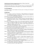
OWL-S is structured to provide three types of knowledge about a service, each
characterized by the question it answers and shown in Figure 8:
• What does the service require of the user(s), or other agents, and provide for them? The
answer to this question is given in the ``profile.'' Thus, the class SERVICE presents a
SERVICEPROFILE
• How does it work? The answer to this question is given in the ``model.'' Thus, the class
SERVICE is describedBy a SERVICEMODEL
• How is it used? The answer to this question is given in the ``grounding.'' Thus, the class
SERVICE supports a SERVICEGROUNDING.
168 Climbing & Walking Robots, Towards New Applications
Fig. 8. OWL-S Ontology Structure
6.2.6. Ontology Structure
To capture the requirements described earlier in the paper, an initial structure for the Robot
Ontology has been developed. A screenshot of the ontology in Protégé is shown in Figure 9.
The column on the left shows the classes that are represented in the ontology (e.g.,
Capability, Robot, User Interface). The box on the right shows the attributes that are associated
with the highlighted class (Robot). Robots have attributes such as
hasCommunicationCapability, hasHumanFactorsCapabilities, hasLocomotionCapabilities,
etc. Each one of these attributes may point to a class (shown in parenthesis next to the
attribute name) which contains more specific information about the value of that attribute.
The main concept in the ontology is Robot, where a robot can roughly be defined as a
mechanism with locomotion and sensing capability which a human user may interact with
from a remote location. A Robot can be thought of as having three primary categories of
information, namely:
• Structural Characteristics – describes the physical and structural aspects of a robot
• Functional Capabilities – describes the behavioral features of the robot
• Operational Considerations – describes the interactions of the robot with the human
and the interoperability with other robots
Test Methods and Knowledge Representation for Urban Search and Rescue Robots 169
Fig. 9. The Robot Capabilities Ontology
In the Robot Ontology, structural characteristics are primarily captured in the definition of
the robot itself. These characteristics include (but are not limited to):
• Size –(e.g., minimum and maximum length, width, and height (depending on robot
configuration))
• Weight
• Tethering (i.e., yes or no)
• Power Source
• Locomotion Mechanism (e.g., wheeled, walking, crawling, jumping, flying, etc.)
• Sensors (e.g., camera, FLIR, LADAR, SONAR, GPS, Audio, Temperature Sensor, etc.)
• Processors
Many of the above are direct attributes of the Robot class. The Robot class and its attributes
are shown in Figure 9. Another important thing to notice in Figure 9 are the classes that end
in the word “stub”. These are meant to be placeholders to integrate in more established (and
hopefully standardized) representations. Examples of these “stubs” include
GeologicalFeatureOntologyStub, InformationStub, MaterialOntologyStub,
PowerSourceStub, ScenarioStub, and SensorStub.
Examples of knowledge captured in the functional capabilities category include (but are not
limited to):
170 Climbing & Walking Robots, Towards New Applications
• Locomotion Capabilities (e.g., max. speed, max. step climbing, max. slope climbing,
etc.)
• Sensory Capabilities (e.g., min. visibility level, map building capability, self-
localization, system health, etc.)
• Operational Capabilities (e.g., working time, setup time, max. force available to push,
mean time before failure (MTBF), mean time between maintenance (MTBM), required
tools for maintenance, run time indicator, sustainment (spares and supplies), etc.)
• Weather Resistance (e.g., max. operating temp, max. submergibility level, etc.)
• Degree of Autonomy (e.g., joint level dependency, drive level dependency, navigation
level dependency, etc.)
• Rubble Compatibility (e.g., ability to historically operate well in certain terrains)
• Communications (e.g., communication media, communication channel frequency,
content standards, information content, communication locking, communication
encryption)
Fig. 10. Operational Capability Attributes
Figure 10 shows an example of the operational capabilities that may be associated with a
robot. Note in this figure that some attributes have “primitive” attributes as their type (e.g.,
float, string, Boolean). This implies that, instead of pointing to another class of object to
capture the data associated with that attribute, the data is captured directly in that primitive
type.
Examples of knowledge captured in the operational considerations category include (but are
not limited to):
Test Methods and Knowledge Representation for Urban Search and Rescue Robots 171
• Human Factors (operator ratio, initial training, proficiency education, acceptable
usability, auto-notification, display type, packaging)
• Intra-Group Interaction (i.e., interaction with other similar robots)
• Inter-Group Interaction (i.e., interaction with other 3
rd
party robots or computers)
Figure 11 shows an example of the human factors attributes that may be associated with a
robot.
Fig. 11. Human Factors Attributes
6.2.7. Future Work
This section describes our progress in developing a robot ontology for USAR. To date, the
Robot Ontology contains 230 classes, 245 attributes (properties), and 180 instances. As the
project progresses, it is expected that the ontology will grow considerably. Although strong
progress has been made, there is still quite a lot of work to be accomplished. Future work
will focus on (in no particular order):
• Continue to specialize the robot ontology structure to provide greater level of detail in
the areas that have already been addressed
• Explore other standards efforts and existing ontologies that can be leveraged, such as
ontologies for sensors, power sources, materials, and environment.
• Continue to incorporate the requirements from the requirements workshops into the
robot ontology structure
• Develop a user interface to help the end user query the ontology. A simple user
interface is shown in Figure 12.
172 Climbing & Walking Robots, Towards New Applications
Fig. 12. Sample User Interface to Ontology
6.3. Structural Collapse Taxonomy
6.3.1. Overview
When a disaster occurs, previously benign terrain may become difficult or impossible to
traverse. Buildings collapse, roads and bridges are destroyed, and previously smooth,
obstacle free terrain may contain large obstacles and discontinuities. In order to perform
search and rescue operations, responders must know what form of mobility they must use
to traverse affected areas. For operational scenarios, the terrain must be assessed in order to
employ assets that posses the correct mobility techniques to get to desired locations. In a
research and development scenario, a description and classification of potential operating
environments is necessary to effectively guide system development. This is particularly
true for the development of performance-based standards for Urban Search And Rescue
(USAR) robots.
An essential element in defining performance metrics is to be able to clearly understand and
describe the operating environment of the system under test. For USAR robotics, both
qualitative and quantitative measures of the environments in which platforms are tested
and deployed are of great interest. For examples of qualitative measures of an environment,
consider trail rating systems for ski slopes or the Beaufort Wind Force Scale for estimating
wind speed from sea state. A quantitative metric in the USAR context could be a specific
measure of the traversibility of the terrain surface derived using techniques such as height,
slope, and roughness estimation from plane fitting, fractal dimension analysis or wavelet
energy statistics. Traversibility is a well-studied discipline, particularly in the context of
unmanned ground vehicle path planning. The challenge is to standardize a universally-
Test Methods and Knowledge Representation for Urban Search and Rescue Robots 173
accepted measure for system evaluation. An interesting qualitative approach would be to
develop a method to score USAR environments similar to the Yosemite Decimal System
(YDS) for evaluating climbing routes. Although subjective, the YDS has evolved into an
effective method for quantifying route difficulty, albeit for only one mobility platform –
humans. From this discussion one can imagine a specific robot platform with an UDS
(USAR Decimal System) number of x for an environment with terrain characterization of y.
A different platform may – and likely will – have a different UDS number for the same
environment. The two measures taken together would provide comparable and verifiable
information about the mobility of the robot platform.
To address the performance metric need, NIST is conducting research in characterizing
terrain traversability for USAR robots (Molino et.al. 2006). The desired result is a set of
algorithms that are capable of analyzing a terrain surface and predicting which robots
would be able to successfully navigate the terrain. To support this research effort, NIST has
gathered high-resolution point clouds of several training disaster scenarios and made those
available for all interested researchers. In addition to characterization algorithms, there is
also a desire to develop representative models of these training scenarios for use in
simulation environment discussed in Section 5. The difficulty is to provide models of
sufficient fidelity that the collapsed terrain is correctly simulated for mobility physics and
maintains important features such as void spaces and terrain roughness, without
overwhelming the current generation of game engines. A related effort involves developing
a framework for integrating building classification, disaster type, and collapse type to
provide general descriptions of probable operating environments.
6.3.2. Structural Collapse Taxonomy
In the context of emergence response and disaster estimation, buildings are normally
classified by model building type and occupancy class. For building types, primary factors
include the building materials used for constructing the structural frame, the lateral-force-
resisting system, and the height of the structure. A simplified classification system is shown
in Table 4.
Type of Construction
1
Wood, Masonry
2
, Steel, Concrete
3
Type of Structure Shear Wall
4
or Moment Frame
Height Low-rise ( 6 stories)
5
, Mid–rise (6-10 stories), High (>10)
Notes:
(1) Refers to materials making up structural frame;
(2) Masonry is typcially further divided into reinforced or unreinforced
(3) Concrete is typically further divided into cast-in-place or pre-cast
(4) Masonry is only shear wall;
(5) Masonry is usually never > 6 stories and wood is usually never > 4 stories. Therefore
masonry and wood default to low-rise
Table 4. Simplified Building Type Schema