InTech-Climbing and walking robots towards new applications Part 11 docx
Bạn đang xem bản rút gọn của tài liệu. Xem và tải ngay bản đầy đủ của tài liệu tại đây (446.64 KB, 30 trang )
Climbing & Walking Robots, Towards New Applications
300
2. Mine Detecting Six-legged Robot (COMET-III) and CAD Model
Figure 1 shows the COMET-III mine detecting six-legged robot, which was developed at
Chiba University. Figure 2 shows a 3D CAD model of COMET-III generated using
mechanical analysis software. One leg of the robot has three degrees of freedom, and each
joint is driven by a hydraulic actuator. The ankle of the leg has two degrees of freedom so
that the sole of the entire bottom surface of the foot touches the ground. The parameters of
COMET-III are shown in Table 1. The mass of the robot is approximately 1,200 [kgf]. The
width of the body is 2,500 [mm], and the length of the body is 3,500 [mm]. The height of the
body is 850 [mm]. An attitude sensor is attached to the body of COMET-III to detect the
pitching and rolling angles. In addition, a six-axis force sensor is attached to each leg. In the
present study, we verify the validity of the proposed attitude control method using a 3D
model.
Fig. 1. COMET-III mine detecting six-legged robot
Fig. 2. 3D CAD model of COMET-III
Table 1. Parameters of COMET-III
Weight 1,200 [kgf]
Width of the body 2,500 [mm]
Length of the body 3,500 [mm]
Height of the body 850 [mm]
Attitude Control of a Six-legged Robot in Consideration of Actuator Dynamics by Optimal Servo
Control System
301
3. Walking Pattern
In the present study, it is desirable that there be little risk of the robot falling down, so that
the attitude control method is examined. Therefore, static walking, which has high stability,
is adopted. The effectiveness of the proposed method is verified by the walking pattern of
five supporting legs. The leg numbers of a six-legged robot are shown in Figure 3. Figure 4
shows the walking pattern by five supporting legs. The period of the swing phase is 3 [s],
and one period of the gait is 18 [s]. In Figure 4, the white area indicates a swing phase, and
the black area indicates a supporting phase. Therefore, the order of the swing motion of the
legs is IIńIIIńIVńIńIVńV.
Fig. 3. Leg numbers
I
II
III
IV
V
VI
L
e
g
N
u
m
b
e
r
0.0
6.0
9.0
18.0
Time[s]
Swing phase
Supporting phase
Fig. 4. Walking pattern
4. Attitude Control Method
This chapter examines the attitude control method that must be applied in the case of
walking and mine detection work on irregular terrain such as a minefield. On even terrain,
each angle of the joint is controlled to follow desired values, which are obtained by inverse-
kinematics. However, on irregular terrain, it is difficult for only position control to keep the
walking and attitude stable. Therefore, it is necessary for the attitude control to recover the
body inclines by adding a force to the supporting legs. This attitude control is realized by
controlling the force in the perpendicular direction of each supporting leg. Moreover, it is
necessary to consider the delay of the hydraulic actuator because the hydraulic actuator is
used for COMET-III.
In the present study, as a model considering the delay of the hydraulic actuator, we make a
mathematical model in which the inputs are the driving torque of the thigh link in the
Climbing & Walking Robots, Towards New Applications
302
supporting legs and the outputs are the height of the body, the pitching angle, and the
rolling angle. In this process, we must seek the force acting the supporting legs, so that the
force is obtained by an approximation formula using the angle and the angular velocity of
the thigh link and the virtual spring and dumping coefficient. The delay of the hydraulic
actuator is considered because this model calculates the force and the attitude in the
perpendicular direction of the supporting leg from the state value of the thigh link. The
optimal servo control system in modern control theory is designed for this model.
4.1 Mathematical Model of the Thigh Link
The leg links of the six-legged robot used in this research have three degrees of freedom,
namely, the shoulder
()
i1
θ
, the thigh
()
i2
θ
, and the shank
()( )
6,,1
3
⋅⋅⋅=i
i
θ
. Equation (1)
shows the transfer function of the thigh link, which is very important in the case of the
attitude control of COMET-III. The delay model of the hydraulic actuator is approximated
by a 1
st
-order Pade approximation.
sT
sT
s
sG
nn
n
2
1
1
2
1
1
2
)(
2
2
2
+
−
•
++
=
ωζω
αω
(1)
Figure 5 shows the step reference response of the PD feedback control system for the system
shown as Eq. (1). A delay of approximately 0.2 [s] occurs.
The description of the state space in Eq. (1) is as follows:
()
tux
aa
x
iii
»
»
»
¼
º
«
«
«
¬
ª
+
»
»
»
¼
º
«
«
«
¬
ª
=
1
0
0
0
100
010
21
(2-a)
[]
»
»
»
¼
º
«
«
«
¬
ª
=
3
2
1
212
0
i
i
i
i
x
x
x
cc
θ
᧨ (
6,,1 ⋅⋅⋅=i
) (2-b)
where
i
x ᧶state variable vector
i
u ᧶input vector
i2
θ
᧶angle of each thigh i ᧶foot number
1
a ,
2
a ,
1
c ,
2
c : coefficients obtained by Eq. (1).
Attitude Control of a Six-legged Robot in Consideration of Actuator Dynamics by Optimal Servo
Control System
303
2XWSXW
5HI
Fig. 5. Step response of the thigh driven by the hydraulic cylinder
θ
2
i
l
t
i
C
e
K
e
Body
F
i
Fig. 6. Relationship between the angle of thigh and the force in the perpendicular direction
of the supporting leg.
4.2 Mathematical Model from the Input of the Thigh Link to the Attitude of the Body
Figure 6 shows the relationship between the angle of the thigh and the force in the
perpendicular direction of the supporting leg. In Fig. 6,
ti
l is the length of the thigh, and
e
C
and
e
K are the dumping and the spring coefficient of the ground, respectively. The
following assumptions are used in Fig. 6.
The shank always becomes vertical to the ground
()
0
3
=
i
θ
.
ཱ The change of
i2
θ
is small.
According to the above assumptions, the force
i
F in the perpendicular direction of the
supporting leg is given by the following equation:
ietiietii
ClKlF
22
θθ
+=
(3)
Substituting Eq. (2) for Eq. (3),
i
F is given by the following equation:
()
iieietiiietii
xcCcKlxcKlF
2212211
++=
iieti
xcCl
232
+ (4)
Climbing & Walking Robots, Towards New Applications
304
Moreover, the height, and the pitching and rolling angles of the body are controlled by
controlling the force in the perpendicular direction of the supporting leg. The motion
equations of the force and the moment equilibrium in the perpendicular direction and the
pitching and rolling axes in the case of support by six legs are given by Eq. (5). Figure 7
shows the coordinates of each foot.
°
¿
°
¾
½
°
¯
°
®
+++++=
+++++=
−+++++=
FxFxFxFxFxFxI
FyFyFyFyFyFyI
MgFFFFFFzM
rr
pp
65544332211
665544332211
654321
θ
θ
(5)
where
M
᧶mass of the body
g
᧶acceleration of gravity
p
I
᧶inertia around the pitching axis
r
I
᧶inertia around the rolling axis
Substituting Eq. (4) for Eq. (5), and by defining the 24
th
-order state value as
,,,,,,,,,[
3612312111
zxxxxxx
rp
θ
θ
⋅⋅⋅=
T
rp
z],,
θθ
, which consists of the state values
of each thigh link, the pitching and rolling angles, the height of the body and its velocity, the
following state equation is obtained:
=
»
»
»
»
»
»
»
»
»
»
»
¼
º
«
«
«
«
«
«
«
«
«
«
«
¬
ª
8
7
6
5
4
3
2
1
x
x
x
x
x
x
x
x
»
»
»
»
»
»
»
»
»
»
»
¼
º
«
«
«
«
«
«
«
«
«
«
«
¬
ª
××
×××××××
×××××××
×××××××
×××××××
×××××××
×××××××
×××××××
3333868584838281
7833333333333333
3333663333333333
33333355333
33333
3333333344333333
3333333333333333
3333333333332233
3333333333333311
00
0000000
0000000
0000000
0000000
0000000
0000000
0000000
AAAAAA
A
A
A
A
A
A
A
+
»
»
»
»
»
»
»
»
»
»
»
¼
º
«
«
«
«
«
«
«
«
«
«
«
¬
ª
8
7
6
5
4
3
2
1
x
x
x
x
x
x
x
x
Attitude Control of a Six-legged Robot in Consideration of Actuator Dynamics by Optimal Servo
Control System
305
+
»
»
»
»
»
»
»
»
»
»
»
¼
º
«
«
«
«
«
«
«
«
«
«
«
¬
ª
××××××
××××××
×××××
×××××
×××××
×××××
×××××
×××××
u
B
B
B
B
B
B
131313131313
131313131313
61313131313
13513131313
13134131313
13131331313
13131313213
13131313131
000000
000000
00000
00000
00000
00000
00000
00000
g
d
»
»
»
»
»
»
»
»
»
»
»
¼
º
«
«
«
«
«
«
«
«
«
«
«
¬
ª
×
×
×
×
×
×
×
8
13
13
13
13
13
13
13
0
0
0
0
0
0
0
(6)
where,
»
»
»
¼
º
«
«
«
¬
ª
=
i
i
i
i
x
x
x
x
3
2
1
( 1=i ᨺ 6 ),
»
»
»
¼
º
«
«
«
¬
ª
=
r
p
z
x
θ
θ
7
,
»
»
»
¼
º
«
«
«
¬
ª
=
r
p
z
x
θ
θ
8
,
»
»
»
¼
º
«
«
«
¬
ª
=
21
0
100
010
aa
A
ii
( 1=i ,ᨿᨿᨿ, 6 ),
»
»
»
¼
º
«
«
«
¬
ª
=
100
010
001
78
A
,
»
»
»
»
»
»
»
¼
º
«
«
«
«
«
«
«
¬
ª
+
+
+
=
i
r
e
i
r
ee
i
r
e
i
p
e
i
p
ee
i
p
e
eeee
i
x
I
lcC
x
I
lcClcK
x
I
lcK
y
I
lcC
y
I
lcClcK
y
I
lcK
M
lcC
M
lcClcK
M
lcK
A
1121
1121
1121
8
(
1=i
,ᨿᨿᨿ,
6
),
»
»
»
¼
º
«
«
«
¬
ª
=
1
0
0
i
B
( 1=i ,ᨿᨿᨿ, 6 ),
»
»
»
»
»
»
»
»
¼
º
«
«
«
«
«
«
«
«
¬
ª
=
6
5
4
3
2
1
u
u
u
u
u
u
u
,
»
»
»
¼
º
«
«
«
¬
ª
=
0
0
1
8
d
Climbing & Walking Robots, Towards New Applications
306
Equation (6) is rewritten as follows:
fgBuAxx ++=
(7)
Here, each row shows the following:
1
st
ᨿᨿᨿ3
rd
: 1
st
ᨿᨿᨿ3
rd
column is Eq. (2) and shows the dynamics of Leg I.
4
th
ᨿᨿᨿ6
th
: 4
th
ᨿᨿᨿ6
th
column is Eq. (2) and shows the dynamics of Leg II.
7
th
ᨿᨿᨿ9
th
: 7
th
ᨿᨿᨿ9
th
column is Eq. (2) and shows the dynamics of Leg III.
10
th
ᨿᨿᨿ12
th
: 10
th
ᨿᨿᨿ12
th
column is Eq. (2) and shows the dynamics of Leg IV.
13
th
ᨿᨿᨿ15
th
: 13
th
ᨿᨿᨿ15
th
column is Eq. (2) and shows the dynamics of Leg V.
16
th
ᨿᨿᨿ18
th
: 16
th
ᨿᨿᨿ18
th
column is Eq. (2) and shows the dynamics of Leg IV.
19
th
ᨿᨿᨿ21
st
: shows the relationship among the angular velocity
p
θ
,
r
θ
, and z
.
22
nd
ᨿᨿᨿ24
th
: shows the equation of motion in Eq. (5).
Fig. 7. Coordinates of each leg
4.3 Optimal Servo System
The servo system that the system shown by Eq. (7) follows to the desired value is designed.
¯
®
++=
−=
fgBuAxx
cxrz
(8)
where, z
is the error vector between the desired vector and the output vector. Equation (8)
is given in matrix form as follows:
r
I
g
d
u
Bx
z
A
c
x
z
»
¼
º
«
¬
ª
+
»
¼
º
«
¬
ª
+
»
¼
º
«
¬
ª
+
»
¼
º
«
¬
ª
»
¼
º
«
¬
ª
−
=
»
¼
º
«
¬
ª
0
00
0
0
(9)
Equation (9) is described in equation form as follows:
Attitude Control of a Six-legged Robot in Consideration of Actuator Dynamics by Optimal Servo
Control System
307
rfgduBxAx
gggggg
+++=
(10)
The feedback (FB) control input
b
u to the actuator driving the thigh link is obtained in
order to minimize the following cost function:
[]
³
∞
+=
0
dtRu(t)u(t)(t)Qx(t)xJ
T
g
T
g
(11)
where
()
nnQ × and
()
mmR × are the weighting matrixes given by the design
specifications, and 0,0 >≥ RQ . The control input to minimize Eq. (11) is as follows:
PxBRu
T
g
o
b
1−
−=
(12)
where
()
nnP × is the solution of the following Ricatti equation:
0
1
=+−+
−
QPBRPBPAPA
T
gg
T
gg
(13)
Figure 8 shows a block diagram of the optimal servo control system.
z
z
r
ᨵ
x
x
$
% &
)
)
Fig. 8. Block diagram of optimal servo control system
4.4 Making a Controlled System for an Uncontrolled System
We examined the controllability for the system as Eq. (10), which is constructed using Eq. (2).
However, it has become an uncontrollable system. The 3
rd
-order delay system is then
approximated to the delay system of the 2
nd
-order model, which is given by following
equation:
2
2
2
2
)(
nn
n
ss
sG
ωζω
ω
++
=
(14)
Climbing & Walking Robots, Towards New Applications
308
In order to obtain the same results for the 3
rd
-order model as were obtained for the 2
nd
-order
model, both the values of the magnitude and the phase in the Bode diagram coincide with
the angular velocity of the walking speed. We searched the values
n
ω
and
ζ
to satisfy the
above condition and obtained the results of
n
ω
= 9 [rad/s] and
ζ
= 0.9. Figure 9 shows a
comparison of the bode plot for the 2
nd
-order system and the 3
rd
-order system. In Fig. 9, the
solid line shows the 2
nd
-order model, and the dashed line shows the 3
rd
-order model. The
solid line drawn around 0.6 [rad/s] at the angular velocity in the figure shows the angular
velocity of the walking in this research. The difference between the systems is significant in
the high-frequency range. However, in this study, in the bandwidth of the walking speed,
the magnitude and the phase coincide. Therefore, we consider this approximation to be
appropriate, and so the attitude control method is designed to replace Eq. (2) with Eq. (14),
and the effectiveness is verified. The system described by Eq. (7) becomes the 19
th
-order
model.
Fig. 9. Comparison of bode plots for the 2
nd
-order system and the 3
rd
-order system
5. 3D Simulation
In this section, in order to verify the validity of the attitude control method considering the
delay of the hydraulic actuator, we examine the walking characteristics on even terrain and
on irregular terrain using the 3D model of the COMET-III six-legged robot. We then discuss
the performance of the attitude control method considering the delay by the simulation
results. The shoulder and shank parts of the leg links are controlled by the PD control,
which is a very popular control method to follow the desired value
ir1
θ
and
ir3
θ
()
6,,2,1 "=ir obtained by solving inverse-kinematics. In addition, in the case of walking
with five supporting legs, the attitude control is applied for the five supporting legs, except for
one swinging leg. The swinging leg is controlled by the PD control.
Attitude Control of a Six-legged Robot in Consideration of Actuator Dynamics by Optimal Servo
Control System
309
5.1 Walking on Even Terrain
Figure 10 shows the 3D simulation results of the proposed attitude control method on even
terrain. Figures 10(a), 10(b), and 10(c) show the time response of the pitching angle, the
rolling angle, and the height of the body, respectively. The variation of the attitude is very
small, and the attitude control works to recover the variation. The six-legged robot can
realize a stable walk.
7LPH>V@
3LWFKLQJDQJOH> UDG@
(a) Pitching angle
7LP
H> V@
5ROOLQJDQJOH>UDG@
(b) Rolling angle
7LPH>V@
+HLJKWRIERG\> P@
(c) Height of the body
Fig. 10. Simulation results in the case of even terrain
5.2 Walking on Irregular Terrain
Figure 11 shows the simulation case for irregular terrain, in which the six-legged robot
walks over a 10 [cm] high step. The six-legged robot starts to climb the step at 3 [s] and
leaves the step at 54 [s]. Figure 12 shows the 3D simulation results for irregular terrain.
Climbing & Walking Robots, Towards New Applications
310
Figures 12(a), 12(b), and 12(c) show the time response of the pitching angle, the rolling angle,
and the height of the body, respectively. The vibrations occur in the pitching and rolling
angles. In addition, approximately 40 [s] is required to settle down at the height of the body
of approximately 0 [m]. However, the influence of the step is slight and the six-legged robot
can realize a stable walk. Moreover, Fig. 13 shows the animation results of the 3D simulation
on irregular terrain. Figures 13(a), 13(b), and 13(c) show animations at the times of 3.45 [s],
70.8 [s], and 136.25 [s], respectively. In Fig. 13(c), two manipulator attached to the front part
of the body are pushed into the ground. However, this causes no particular problem,
because it does not influence the walking operation. Based on the above-mentioned results,
the attitude control method that considers the dynamics of the actuator proposed in the
present study is effective.
Fig. 11. Case of walking on uneven terrain
7LPH>V@
3LW FKLQJDQJOH>UDG@
(a) Pitching angle
7LPH>V@
5ROOLQJ DQJOH> UDG@
(b) Rolling angle
Attitude Control of a Six-legged Robot in Consideration of Actuator Dynamics by Optimal Servo
Control System
311
7LPH>V@
+HLJKWRIERG\> P@
(c) Height of the body
Fig. 12. Simulation results in the case of irregular terrain
(a) Simulation time: 3.45 [s]
(b) Simulation time: 70.8 [s]
(c) Simulation time: 136.25 [s]
Fig. 13. Animations of walking on uneven terrain
Climbing & Walking Robots, Towards New Applications
312
6. Conclusion
In the present study, we examined the attitude control method considering the delay of the
hydraulic actuator whereby the mine detection six-legged robot can realize stable walking
on irregular terrain without to make an orbit of the foot for irregular terrain. The following
results were obtained.
(1) As an attitude control method considering the delay of the actuator of the thigh links,
we derive a mathematical model in which the inputs are the driving torque of the thigh
links in the supporting legs and the outputs are the height of the body, the pitching
angle, and the rolling angle.
(2) The 3
rd
-order delay system is approximated as a 2
nd
-order delay system, and an
optimal servo control system is applied as the attitude control method.
(3) The validity of the proposed attitude control method is discussed based on 3D
simulations of walking on even terrain and irregular terrain.
The effectiveness of the proposed control method will be examined experimentally in the
future. Moreover, the method by which to improve the transition response with the time
delay system will be examined.
7. References
Uchida, H. & Nonami, K. (2001), Quasi force control of mine detection six-legged robot
COMET-I using attitude sensor, Proceeding of 4
th
International Conference on Climbing
and Walking Robots, pp 979-988, ISBN 1 86058 365 2, Karlsruhe, Germany, September,
2001, Professional Engineering Publishing, London.
Uchida, H. & Nonami, K. (2002), Attitude Control of Six-Legged Robot Using Optimal
Control Theory, Proceeding of 6
th
International Conference on Motion and Vibration
Control, pp 391-396, Saitama, Japan, August, 2002, The Dynamics, Measurement
and Control Division of Japan Society of Mechanical Engineers, Tokyo.
Uchida, H. & Nonami, K. (2003), Attitude control of six-legged robot using sliding mode
control, Proceeding of 6
th
International Conference on Climbing and Walking Robots, pp
103-110, ISBN 1 86058 409 8, Catania, Italy, September, 2003, Professional
Engineering Publishing, London.
15
A 4WD Omnidirectional Mobile Platform and its
Application to Wheelchairs
Masayoshi Wada
Dept. of Human-Robotics, Saitama Institute of Technology
Japan
1. Introduction
The aging of society in general and the declining birth rate have become serious social issues
world wide, especially in Japan and some European countries. It is reported in Japan that
the number of people over 65 years old would reach 30,000,000 in 2012 and increase to over
30% of total population by 2025 (estimated and reported in 2006 by the National Institute of
Population and Security Research, Japan). Wheelchairs are currently provided mainly for
handicapped persons however, such rapid growth in the elderly population suggests that
the numbers of electric wheelchair users will soon increase dramatically.
Currently, reconstruction of facilities to make them barrier-free environments is a common
method. Such reconstruction of existing facilities is limited mainly to large cities because
large amounts of money can be invested in facilities used by large numbers of people.
However, it would be economically inefficient and therefore quite difficult to reconstruct
facilities in small towns occupying small populations. Moreover, the aging problem is more
serious in such small towns in local regions because of the concurrent decline in the number
of young in rural areas where the towns are dispersed and not centralized. Thus, economic
and time limitations make the reconstruction of existing facilities to accommodate
wheelchair users unfeasible.
One solution to this problem would be to improve wheelchair mobility to adapt to existing
environments. Electric wheelchairs, personal mobiles, and scooters are currently
commercially available not only for handicapped persons but also for the elderly. However,
those mobile systems do not have enough functionalities and capabilities for moving around
existing environments including steps, rough terrain, slopes, gaps, floor irregularities as
well as insufficient traction powers and maneuberabilities in crowded areas. By the
insufficient capabilities of the mobile system, independency of users is inhibited. For
example, wheelchair users in Japan must call station staff for help for both getting on and off
train cars, because large gaps and height differences exist between station platforms and
train cars. To alleviate these difficulties, station staff place a metal or aluminum ramp
between the platform and the train. This elaborate process may make an easy outing
difficult and cause mental stress.
O
pen Access Database www.i-techonline.co
m
Source: Climbing & Walking Robots, Towards New Applications, Book edited by Houxiang Zhang,
ISBN 978-3-902613-16-5, pp.546, October 2007, Itech Education and Publishing, Vienna, Austria
Climbing & Walking Robots, Towards New Applications
314
Addition to this, electric wheelchairs are difficult to maneuver especially for elderly people
who have little experience using a joystick to operate a driven wheel system. Current
wheelchairs need a complex series of movements resembling parallel automobile parking
when he or she wants to move sideways. The difficulties in moving reduce their activities of
daily living in their homes and offices.
From this viewpoint, the most important requirements for wheelchairs are maneuverability
in crowded areas indoors and high mobility in rough terrain outdoors. Current wheelchair
designs meet one or the other of these requirements but not both. To ensure both
maneuverability and mobility, we propose an omnidirectional mobile system with a 4WD
mechanism.
In this chapter, we discuss the development of the omnidirectional mechanism and control
for the 4WD. After analyzing basic 4WD kinematics and statics, basic studies are presented
using a small robotic vehicle to demonstrate the advantages on the 4WD over conventional
drive systems, such as rear drive (RD) or front drive (FD). Based on the experimental data, a
real-scale wheelchair prototype was designed and built. To demonstrate the feasibility of the
proposed system, including omnidirectional mobility and high mobility, the result of
prototype test drives are presented.
2. Existing Wheelchair Drive Mechanisms
2.1 Differential Drives
The differential drives used by most conventional wheelchairs, both hand-propelled and
electrically driven, have two independent drive wheels on the left and right sides, enabling
the chair to move back and force with or without rotation and to turn in place. Casters on
the front or back or both ends keep the chair level (Fig.1) [Alcare], [Meiko]. This drive
maneuver in complex environments because it rotates about the chair's center in a small
radius.
The differential drive's drawback is that it cannot move sideways. Getting a wheelchair to
move sideways involves a complex series of movements resembling parallel automobile
parking. The small-diameter casters most commonly used also limit the wheelchair's ability
to negotiate steps.
Fig. 1. Differential drive wheelchair with four casters front and back
4WD Omnidirectional Mobile Platform and its Application to Wheelchairs
315
2.2 Differential 4WD Drives
The 4WD drive was invented in 1989 [Farnam, 1989] (Fig. 2(a)) and was recently applied to a
product [Kanto] to enhancing differential drive traction and step negotiation (Fig. 2(b)). The
4WD drive has a pair of omniwheels on the front and a pair of normal wheels on the back.
The omniwheel and normal wheel on the same side of the chair are connected by a
transmission and driven by a common motor to ensure the same speed in the direction of
movement, so all four wheels of the 4WD provide traction. Motors on the left and right
drive normal/omniwheel pairs via synchronous-drive transmissions to allow differential
driving by the 4WD.
The 4WD controlled in differential drive mode has the center of rotation at the mid-point of
the normal back wheels, meaning that spinning in a turn requires more space than for the
original differential drive (dotted curve, Fig. 3), limiting indoor maneuverability.
(a) (b)
Fig. 2. 4WDdrive (a) and a wheelchair with 4WD [Farnam, 1989](b)
2.3 Omnidirectional Drive
Omnidirectional drives used on electric wheelchairs [Fujian], [Wada, 1999] were developed
to enhance standard wheelchair maneuverability by enabling them to move sideways
without changing chair orientation. Examples include the Universal and Mechanum wheels.
In Fig. 3, an omnidirectional vehicle with Mechanum wheels uses rollers on the large
wheel's rim inclining the direction of passive rolling 45 degrees from the main wheel shaft
and enabling the wheel to slide in the direction of rolling. The standard four-Mechanum-
wheel configuration assumes a car-like layout.
The inclination of rollers on the Mechanum wheel causes the contact point relative to the
main wheel to vary, resulting in energy loss due to conflicts among the four motors. Because
four-point contact is essential, a suspension mechanism is needed to ensure 3-degree-of-
freedom (3DOF) movement.
Climbing & Walking Robots, Towards New Applications
316
Fig. 3. Four-wheel omnidirectional wheelchair
2.4 Summary
Maneuverability and mobility are essential to barrier-free environments. As discussed
above, existing wheelchair designs fulfill one requirement or the other but not both.
Omnidirectional wheelchairs are highly maneuverable indoors but dynamically unwieldy
outdoors, while 4WD wheelchairs, although highly mobile outdoors, require a 4WD
mechanism that prevents them from changing their orientation independently. The
maneuverability of the original 4WD must thus be improved to move in complex
environments.
To meet these requirements in a single wheelchair design, we propose a new
omnidirectional 4WD in the sections below. Although invented in 1989, the kinematics and
statics of the original 4WD configuration has not been discussed in depth. In basic studies
enabling 4WD to be applied to an omnidirectional mobile base, we analyze 4WD statics and
kinematics before discussing the wheelchair's omnidirectional mechanism and control
algorithm.
3. Static Analysis for Wheel-and-step
Figure 4 shows a vehicle with a 4WD configuration in which the motor torque is distributed
and transmitted to both front and rear wheels. In this configuration, the front and the rear
wheels are actively driven in the same speed.
Before bumping a step edge, both the front and the rear wheel provide respective traction
forces, F
f
and F
r
, in the horizontal direction to propel the vehicle forward. However, right
after a wheel touches a step edge, the traction force distributed to the front wheel, F
f
,
changes its direction and applies the moment to flip up the center of the front wheel that has
contacted the step edge. The applied force from the rear wheel, F
r
, is still directed
horizontally after the bump. Figure 5 shows statics of the front wheel in a 4WD system
contacting a step edge. In this case, the condition to surmount the step is derived as,
θ
θ
sincos
frf
WFF ≥+
(1)
4WD Omnidirectional Mobile Platform and its Application to Wheelchairs
317
When the vehicle weight and motor torque are equally distributed to the front and rear
wheel, namely W
f
=W
r
, F
f
=F
r
=F/2. Equation (1) would be,
θ
θ
cos1
sin2
+
≥ WF
(2)
Equation (2) gives the required minimum motor power for overcoming the specific step
height. Next, we have to consider the limitation of the traction forces which are restricted by
the friction coefficient between the wheel and the ground or step edge.
Let
μ
be the friction coefficient at the contact point on the wheel. The traction force at each
wheel is restricted as,
rr
ef
WF
WF
μ
μ
≤
≤
(3)
where W
e
is a force component directing along the line O-B in the figure which is
represented as,
θ
θ
sincos
rfe
FWW +=
(4)
From Eq. (3) and Eq. (4) we get,
()
θμθμθ
cossinsin
2
rfrf
WWWW ++≤
(5)
Again we suppose that the vehicle weight is equally distributed and motor torque is
transmitted in the same ratio to the front and the rear wheels, the slip condition for 4WD is
given by following relationships from Eq. (5).
θ
θ
μ
sin
cos1−
≤
)0sin( ≠
θ
if
(6)
Theoretical load curves derived by Eq. (2) and Eq. (6) are shown together with the
experimental results in Section 6.
Climbing & Walking Robots, Towards New Applications
318
τ
τ
/2
τ
/2
Active
wheel
Active
wheel
Synchro-drive
transmission
F
f
F
r
Fig. 4. 4WD drive transmission
θ
τ
/2
F
f
F
r
W
f
r
O
A
B
d
W
e
Fig. 5. Statics of the 4WD front wheel contacting a step edge
4. Kinematics of 4WD Drive Mechanism
In this chapter, we analyze the motions of the front omniwheels driven by synchro-drive
transmissions for deriving the kinematic condition for non-slip drive.
Figure 6 is a schematic top view of a 4WD mechanism. When the two rear wheels are driven
by independent motors to travel in velocities v
R
and v
L
on the ground with no slips, the
wheels allow the vehicle to rotate about the point on the ground indicated O
r
(Instantaneous
Center of Rotation, ICR) in Fig. 6. It is well known that the vehicle’s forward velocity and
rotation are represented by the wheel velocities as follows,
W
vv
vv
x
LR
v
LR
v
−
=
+
=
φ
2
(7)
where W is a tread of the mobile base (displacement of the two parallel wheels). Now
considering a velocity vector on a specific point p on the 4WD mechanism which location is
(x
p
, y
p
) as shown in the figure. The components of vector v
p
along the X- and Y-directions of
the vehicle coordinate system, indicated as v
px
and v
py
, are represented as,
4WD Omnidirectional Mobile Platform and its Application to Wheelchairs
319
pvpy
pvvpx
v
xv
θφ
θφ
cos
sin
A
A
=
−=
(8)
Note that
pp
y=
θ
sinA and
pp
x=
θ
cosA , and the following relations are derived.
()
LR
p
py
L
p
R
p
px
vv
W
x
v
v
W
y
v
W
y
v
−=
¸
¸
¹
·
¨
¨
©
§
++
¸
¸
¹
·
¨
¨
©
§
−=
2
1
2
1
(9)
R
W/ 2
D
v
R
v
L
v
px
v
p
v
py
W/ 2
X
Y
O
p
φ
v
.
O
r
L
p
R
p
L
x
p
y
p
l
θ
p
Fig. 6. 4WD kinematics
The location of the contact point of the front left omniwheel is defined as (x
p
, y
p
)=(D, W/2)
on the vehicle coordinate system. From Eq. (9), the velocity components at left omniwheel
are represented as,
()
LRpy
Lpx
vv
W
D
v
vv
−=
=
(10)
Climbing & Walking Robots, Towards New Applications
320
Thus only when y
p
= W/2, velocity component in the X-direction of the left omniwheel
becomes completely identical to the rear wheel velocity and is independent from the right
wheel motion. The velocity component in the Y-direction is generated as a passive motion
by free rollers on the omniwheel. The velocity components of right side omniwheel can be
derived in the same manner as,
()
LRpy
Rpx
vv
W
D
v
vv
−=
=
(11)
From these analyses, it is clear that omniwheels can follow the rear wheel motion with no
slip or conflict as long as the contact point of the omniwheel is located completely on the line
which is passing through the contact point of the rear wheel with directing the wheel rolling
direction. Thus, omni and normal wheel pairs on the same side of the 4WD mechanism can
be driven by a synchro-drive transmission with a common motor.
5. Powered-Caster Control System
5.1 Powered-caster Control for Twin Caster Configuration
The powered-caster drive systems were developed by the authors group [Wada, 1996],
[Wada, 2000]. The drive system enables holonomic and omnidirectional motions with the
use of normal wheels rather than a class of omniwheels.
Two types of caster configurations are available for the powered-caster drive system
including the single-caster type (a normal wheel with a steering shaft supporting the wheel
with a caster offset) and the twin-caster type (two parallel normal wheels supported by a
steering shaft with a caster offset). To apply the powered-caster control, the configuration of
a wheel mechanism has to have a caster offset between drive wheel(s) and a steering axis.
Figure 7 illustrates an omnidirectional vehicle design for AGV (Automated Guided Vehicle)
with a drive unit which forms a twin caster configuration [Wada, 2000]. Two drive wheels
and a steering mechanism are mounted on the drive unit where each wheel or a steering is
driven by a respective motor. The displacement between the midpoint of the two wheels
and the center of the steering shaft, called caster offset, s, and the displacement between two
wheels, called vehicle tread, W, are respectively indicated in Fig. 7. Thus, the wheels and the
steering shaft form a twin-caster configuration. Coordination of these three motors allows
the vehicle body to move in an arbitrary direction with arbitrary magnitude of velocity from
any configuration of the drive unit.
Relationships between wheel velocities and the motion of the drive unit, which is defined as
the velocity and the rotation at the center of the steering axis are derived as (see [Wada,
2000] for details),
4WD Omnidirectional Mobile Platform and its Application to Wheelchairs
321
O
o
X
o
Y
o
X
v
Y
v
O
v
Drive unit
r
W
s
X
c
Y
c
Vehicle body
ω
L
ω
R
θ
v
ω
s
Fig. 7. Omnidirectional AGV with a twin-caster drive
¸
¸
¹
·
¨
¨
©
§
¸
¸
¸
¹
·
¨
¨
¨
©
§
−
−=
¸
¸
¸
¹
·
¨
¨
¨
©
§
L
R
v
v
v
WrWr
WrsWrs
rr
y
x
ω
ω
θ
//
//
2/2/
(12)
where r is the wheel radius. Note here that the rotation of the drive unit,
v
θ
, in Eq. (12) is
not independent from the translation velocity,
v
x
and
v
y
, the third motor is required to
compensate for the rotation of the drive unit and directing the vehicle body to the desired
direction. In the wheelchair applications, desired motion is given along the vehicle body
coordinate system since a joystick is fixed and moves together with the chair. Considering
these effects, Eq. (12) can be resultantly united with the rotation of the vehicle body as
shown below.
¸
¸
¸
¹
·
¨
¨
¨
©
§
¸
¸
¸
¹
·
¨
¨
¨
©
§
−
=
¸
¸
¸
¹
·
¨
¨
¨
©
§
S
L
R
c
c
c
WrWr
JJ
JJ
y
x
ω
ω
ω
θ
1//
0
0
2221
1211
(13)
Climbing & Walking Robots, Towards New Applications
322
where,
W
rsr
J
W
rsr
J
W
rsr
J
W
rsr
J
vv
vv
vv
vv
θθ
θθ
θθ
θθ
cos
2
sin
cos
2
sin
sin
2
cos
sin
2
cos
22
21
12
11
−=
+=
+=
−=
(14)
Note that
θ
v
is rotation of the vehicle body relative to the drive unit, namely rotation created
by the third motor. A 3x3 matrix in the right side of the Eq. (13), called a Jacobian, is a
function of the orientation of the drive unit relative to the vehicle body,
θ
v
. All elements in
the Jacobian can always be calculated, and determinant of the Jacobian may not be zero for
any
θ
v
. Therefore there is no singular point on the mechanism and an inverse Jacobian
always exists. 3D motion commands,
c
x
,
c
y
and
c
θ
, are translated into three motor
references by the inverse of Eq. (13), i.e. inverse kinematics. The three motors are controlled
to provide the reference angular velocities by independent speed controllers for
omnidirectional movements. Thus, holonomic 3DOF motion can be realized by the
proposed mechanism.
This class of omnidirectional mobility, so called “holonomic mobility”, is very effective to
realize the high maneuverability of a wheelchair by an easy and simple operation.
5.2 Powered-caster Control for 4WD Mechanism
Now we refer back to control of the 4WD mechanism. As mentioned in Section 2.2, for
applying 4WD to a wheelchair design, there must be an offset between the rear wheels and
the center of the chair to allow enough room on the front side for mounting the omniwheels.
When the wheelchair is controlled in a differential drive manner, the offset distance makes
the maneuverability of the wheelchair worse, as mentioned previously. However, that offset
allows us to apply the powered-caster control for the 4WD mechanism with a third motor.
Therefore, by adding the third motor to the original 4WD mechanism for rotating a chair,
coordinated control of three motors enables the wheelchair to realize independent 3DOF
omnidirectional motion.
For wheelchair applications, a 4WD drive unit can be held level since omniwheels are
installed in the front end of the drive unit. Therefore, no caster is required to support a chair
base or the drive unit. Figure 8 illustrates a schematic of an omnidirectional mobile base
with a 4WD mechanism.
4WD Omnidirectional Mobile Platform and its Application to Wheelchairs
323
O
o
X
o
Y
o
X
v
Y
v
O
v
Drive unit
r
W
s
X
c
Y
c
Chair base
ω
L
ω
R
θ
v
ω
s
Fig. 8. Omnidirectional mobile base with 4WD
6. Basic Experiments Using a Small Robot
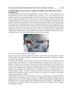
Figure 9 shows an overview of a small vehicle designed for experiments for fundamental
studies. The vehicle is equipped with four wheels, where the front two wheels are
omniwheels and rear two are normal rubber tires. A servo motor is installed on each side of
the vehicle to drive the right or left wheel(s) independently. The servo motor for driving
wheels is located at the midpoint between the front and rear wheels, as shown in the figure.
Each motor torque is distributed to the front and rear wheel shafts by pulley-belt synchro-
drive transmission(s). The dimension of the prototype is approx. 450 mm in width and
350 mm in length. The vehicle body is made of aluminum on which four wheels and two
motors are mounted. All four wheels are 100 mm in diameter. The wheelbase is 200 mm and
the tread is 430 mm. The capacity of the motors is 100 W.
Fig. 9. Omnidirectional mobile platform with 4WD for experiments