InTech-Climbing and walking robots towards new applications Part 14 docx
Bạn đang xem bản rút gọn của tài liệu. Xem và tải ngay bản đầy đủ của tài liệu tại đây (980.28 KB, 30 trang )
Climbing and Walking Robots, Towards New Applications
390
Fig. 7. Simulation of suction pressure in original design
Fig. 8. Simulation of suction pressure in Scale 2
City-Climber: A New Generation Wall-climbing Robots
391
Fig. 9. Simulation of suction pressure: fully open
Fig. 10. Simulation of suction pressure: 1cm gap between wall and chamber
Climbing and Walking Robots, Towards New Applications
392
Fig. 11. Simulation of suction pressure: fully sealed
3. City-Climber Prototypes
3.1 City-Climber Prototype-I
Isolation Seal
Isolation Rim
bristle Skirt
Suction Motor
Inner Exhaust
Outer Exhaust
Drive Wheel
Passive Wheel
Drive Wheel
Platform
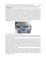
Fig. 12. Exploded view of City-Climber prototype-I.
City-Climber: A New Generation Wall-climbing Robots
393
Fig. 12 shows the exploded view of the City-Climber prototype-I that consists of the vacuum
rotor package, an isolation rim, a vacuum chamber with flexible bristle skirt seal, and
internal 3-wheel drive. The entire bristle surface is covered in a thin sheet of plastic to keep a
good sealing, while the flexing of bristle allows the device to slide on rough surfaces. A
pressure force isolation rim connecting the platform and the bristle skirt seal is made of re-
foam. The rim improves the robot mobility, and also enhances sealing by reducing the
deformation of the skirt. The driving system and the payload are mounted on the platform,
thus the re-foam makes the skirt and the robot system adaptable to the curve of rough
surfaces. Fig. 13 shows a City-Climber prototype-I operating on brick wall.
Fig. 13. City-Climber prototype-I approaching a window on brick wall, a CMU-camera is
installed on a pan-tilt structure for inspection purpose.
3.2 City-Climber Prototype-II
The City-Climber prototype-II adopts the modular design which combines wheeled
locomotion and articulated structure to achieve both quick motion of individual modules on
planar surfaces and smooth wall-to-wall transition by a set of two modules. Fig. 14 shows
the exploded view of one climbing module which can operate independently and is
designed with triangle shape to reduce the torque needed by the hinge assembly to lift up
the other module. To traverse between planar surfaces two climbing modules are operated
in gang mode connected by a lift hinge assembly that positions one module relative to the
other into three useful configurations: inline, +90°, and -90°. Responding the electronic
controls, a sequence of translation and tilting actions can be executed that would result in
the pair of modules navigating as a unit between two tangent planar surfaces; an example of
this is going around a corner, or from a wall to the ceiling. Fig. 15 shows a conceptual
drawing of two City-Climber modules operating in gang mode that allow the unit to make
wall-to-wall and wall-to-ceiling transitions. Fig. 16 shows the City-Climber prototype-II
resting on a brick wall and ceiling respectively. The experimental test demonstrated that the
City-Climber with the module weight of 1kg, can handle 4.2kg additional payload when
moving on brick walls, which double the payload capability of the commercial vortex
climber.
Climbing and Walking Robots, Towards New Applications
394
Suction Motor
Isolation Rim
Inner Exhaust
Outer Exhaust
Vacuum Impeller
Isolation Seal
bristle Skirt
Lift Hinge Assembly
Lift Motor &
Gearbox
Drive Wheels
Passive Wheel
Platform
Fig. 14. Exploded view of City-Climber prototype-II
Fig. 15. Two robot modules connecting by a hinge in +90°, and -90° configurations, being
able to make wall-to-wall, and wall-to-ceiling transitions
Fig. 16. The City-Climber prototype-II rests on a brick wall and sticks on a ceiling
respectively
City-Climber: A New Generation Wall-climbing Robots
395
3.3 City-Climber Prototype-III
The most important improvements in City-Climber prototype-III are the redesign of
transition mechanism and the adoption of 6-wheel driving system to increase the contact
friction and avoid wheel slippage while climbing vertical walls. Note that the wheels are
outside of the robot frame, making it possible for each module to make ground to wall
transition with ease (see video demonstration on ). The two
modules are closely coupled to reduce the torque required to lift up other module, as shown
in Fig. 17. Due to efficient placement of the driving system the robot is still capable of +/- 90
degree transitions, similar to prototype-II. Fig. 18 shows the robot prototype III and Fig. 19
shows the exploded view with each module consists of a vacuum rotor package and is
closely coupled by shared center axel and transition motor. Same as the prototype-II, the
new design still uses one motor for lift/transition and two motors for driving. The two
driving motors drive the two center wheels (left and right) independently, and via the right
and left belts, drive the front and rear wheels. Additional multiple modules could be linked
together in the future to a form snake-like version.
Fig. 17. City-Climber prototype-III, two modules are closely coupled with one transition
motor placed in the middle and two other motors drive the two center wheels (left
and right), and via the driving belts drive the front and rear wheels
Fig. 18. City-Climber prototype-III: a) One module resting on a brick wall; b) two module
Climbing and Walking Robots, Towards New Applications
396
Fig. 19. Exploded view of City-Climber prototype-III
4. Control System
Good mechanical structure cannot guarantee excellent performance. It is crucial to design an
effective control system to fully realize the potential of the City-Climber and empower it
with intelligence superior to other robots. Resource-constrained miniature robots such as the
City-Climber require small but high-performance onboard processing unit to minimize
weight and power consumption for prolonged operation. The TMS320F2812 digital signal
processing (DSP) chip from Texas Instruments (TI) Inc. is an ideal candidate for an
embedded controller because of its high-speed performance, its support for multi-motor
control and the low power consumption. This section describes the DSP-based control
system design.
4.1 Actuators and Sensor Suite
To minimize weight and complexity, the City-Climber robots use limited number of
actuators and sensor components. The actuators in each module include the two drive
motors, one lift motor, all of them are DC servo motors with encoder feedback, and one
suction motor. The primary sensor components include pressure sensors for monitoring the
pressure level inside the vacuum chamber; ultrasonic sensors and infrared (IR) sensors for
distance measurement and obstacle avoidance; a MARG (Magnetic, Angular Rate, and
Gravity) sensor for tilt angle and orientation detection. For remote control operation the
robot has a wireless receiver module, which communicates with the transmitter module in a
remote controller. All the signals from those components and sensors need to be processed
City-Climber: A New Generation Wall-climbing Robots
397
and integrated into an on-board control system.
Apart from the primary sensors which are critical for operation, additional application
sensors can be installed on the robot as payloads when requested by specific tasks. For
reconnaissance purpose, a wireless pin-hole camera is always installed and the video images
are transmitted to and processed at a host computer.
Fig. 20. Hardware design of DSP-based control system
4.2 Hardware Design
The F2812 is a 32-bit DSP controller (TI 2003) targeted to provide single chip solution for
control applications. This chip provides all the resources we need to build a self-contained
embedded control system. Fig. 20 illustrates the hardware connection based on F2812 DSP.
The DSP controller produces pulse width modulation (PWM) signals and drives the motors
via 4 Motorola H-bridge chips (Motorola 33887). F2812 DSP has two built-in quadrature
encoder pulse (QEP) circuits. The encoder readings of the two drive motors are easily
obtained using the QEP channels while a software solution (Xiao et al.; 2000) is implemented
to get encoder reading of the lift motor using the Capture units of the DSP. With the encoder
feedback, a closed-loop control is formed to generate accurate speed/position control of the
drive motors and lift motor. The speed of the vacuum motor is adjusted with the feedback
33887
Motorola
F2812 DSP
33887
Motorola
M2
M3
M1
OUT1
OUT2
OUT2
IN1
IN2
IN1
IN2
PWM1
PWM2
PWM3
PWM4
PWM5
PWM6
PWM7
PWM8
M1
Encoder
M2
Encoder
M3
Encoder
ChA
ChA
ChA
ChB
ChB
ChB
QEP1
QEP2
QEP3
QEP4
CAP3
CAP6
ADCINB4
ADCINB3
P-Sensor2
P-Sensor1
Presssure
Sensor
GPIOB6
Valve1
SCI-B
GPIOF, 8,9,10,11,12,13
6 Digital I/O Sensors
GPIOB2
EN
GPIOB3
EN
GPIOB4
GPIOB5
RS232 Receiver
IR
Sensor
(SHARP)
ADCINA7
ADCINB5
ADCINB6
ADCINB7
OUT1
33887
Motorola
OUT2
IN1
IN2
EN
OUT1
33887
Motorola
OUT2
IN1
IN2
EN
OUT1
XINT1
GPIOB7
FB
FB
FB
M3
Drive Motor
Decoder
Ultrasonic
Sensor
eco
Trig
MARG
Magnetic
Accelerometer
GYRO
ADCINB0
ADCINB1
ADCINB2
ADCINA3
ADCINA0
ADCINA1
ADCINA2
ADCINA4
ADCINA5
ADCINA6
RS232Host Computer
SCI-A
Drive Motor
Lift Motor
Vacuum Motor
Climbing and Walking Robots, Towards New Applications
398
from the pressure sensors. Using Analog to Digital Converter (ADC) the pressure inside the
vacuum chamber is monitored continuously. If the pressure reading is higher than a
threshold, the vacuum motor increases the speed to generate more suction force. If the
pressure drops too low and the suction force prevent the robot from moving, the vacuum
motor will slow down to restore the pressure. An ideal pressure will be maintained which
keeps the robot sticking to the wall and with certain mobility.
The climbing robot can be operated both manually and semi-autonomously. Infrared
sensors are installed to measure distances from close proximity objects, while ultrasonic
sensors are used to measure distance from objects that are far away. The infrared sensor has
a reliable reading in the range of 10 cm to 80 cm and the ultrasonic sensor has a reliable
range between 4 cm to 340 cm. External interrupt (XINT) channel is connected to the
ultrasonic sensor to measure the time-of-fly of sound chirp and convert the measurement to
distance reading. In order for the climbing robot to understand its orientation and tilt angle,
a MARG sensor is integrated into the control system. The MARG sensor (Bachmann et al.,
2003) is composed of nine sensor components of three different types affixed in X-Y-Z three
axes: the magnetic sensor, accelerometer, and gyro. The magnetic sensors allow the robot to
know its orientation with respect to a reference point (i.e., north pole). The accelerometers
measure the gravity in three axes and thus provide tilt angle information to the robot. The
gyro sensors measure angular rates which are used in the associated filtering algorithm to
compensate dynamic effects. The DSP controller processes the inputs from the nigh MARG
sensor components via ADC and provides the robot with dynamic estimation of 3D
orientation which is very important for robot navigation.
There are two ways the DSP controller communicates with external sources. Host computer
can exchange data with DSP controller via serial communication interface (SCI) using RS232
protocol. Another source that can send commands to the DSP controller is a radio remote
controller. This is accomplished by interfacing a receiver with a decoder and then
translating the commands into a RS232 protocol compatible with SCI module.
Fig. 21. Control system block diagram
City-Climber: A New Generation Wall-climbing Robots
399
4.3 Software Modules
The control system structure is illustrated in the block diagram as shown in Fig. 21. The
physical actuators and sensors are represented in the right block. Other blocks represent the
on-board software modules including command interpreter, task level scheduler, trajectory
planner, motor controller and motion planner. The operator commands, such as “move
forward”, “make left turn”, are transmitted from the remote controller held by a human
operator and decoded by the on-board command interpreter. The generated task level
commands are then fed into the task level scheduler. The task level scheduler uses a finite
state machine to keep track of robot motion status and decompose the command into
several motion steps. The trajectory planner interpolates the path to generate a set of desired
joint angles. The digital motor controller then drives each motor to the desired set points so
that the robot moves to the desired location. The motion planner module generates a
feasible motion sequence and transmits it to the task level scheduler. After the motion
sequence has been executed, the robot is able to travel from its initial configuration to its
goal configuration, while avoiding the obstacles in the environment.
5. Experimental Test
Experiments were conducted to evaluate the performance of City-Climber prototypes. The
main areas of functionalities and several key experimental tests are recorded in video which
is downloadable from website The specifications of the
City-Climber robots are listed in table 1.
Table1. Physical specifications of the City-Climber robots
It was demonstrated that the City-Climber robots are able to move on various wall surfaces,
such as brick, wood, glass, stucco, plaster, gypsum board, and metal. With the module
weight of 1kg, the City-Climber can generate enough adhesion force to carry additional
4.2kg payload. The video also shows that the City-Climber can operate on real brick wall,
and cross surface gaps without difficulty.
6. Conclusion and Future Work
This chapter highlights some accomplishments of CCNY robotics team in developing novel
wall-climbing robots that overcome the limitations of existing technologies, and surpass
them in terms of robot capability, modularity, and payload. The performance of several
City-Climber prototypes are demonstrated by the experimental results recorded in video. By
integrating modular design, high-performance onboard processing unit, the City-Climber
robots are expected to exhibit superior intelligence to other small robot in similar caliber.
The next step of the project is to optimize the adhesion mechanism to further increase
suction force and robot payload, and to improve the modularity and transition mechanism
to allow the robot re-configure its shape to adapt to different missions. Other directions are
Climbing and Walking Robots, Towards New Applications
400
to increase the robot intelligence by adding new sensors, improving on-board processing
unit, and developing software algorithms for autonomous navigation.
7. Acknowledgment
This work was supported in part by the U.S. Army Research Office under grant W911NF-05-
1-0011, and the U.S. National Science Foundation under grants ECS-0421159, CNS-0551598,
CNS-0619577 and IIS-0644127. The authors would like to thank all the team members for
their contributions to the climbing robot project, especially Matt Elliot and William Morris
for mechanical design, Parisa Saboori for Fluent simulation, Angel Calle and Ravi Kaushik
for control system design.
8. References
Asbeck, A; Kim, S.; Cutkosky, M. R.; Provancher, W. R. & Lanzetta, M. (2006). Scaling Hard
Vertical Surfaces with Compliant Microspine Arrays. International Journal of Robotics
Research, Vol. 15, No. 12, pp. 1165-1180, 2006.
Autumn, K.; Liang, Y; Hsieh, T.; Zesch, W.; Chan, W. P.; Kenny, T.; Fearing, R. & Full R. J.
(2000). Adhesive force of a single gecko foot-hair. Nature, 405:681-684, 2000.
Bachmann, E. R.; Yun, X. P.; McKinney, D.; McGhee, R. B. & Zyda, M. J. (2003). Design and
implementation of MARG sensors for 3-DOF orientation measurement of rigid
bodies, Proceeding of 2003 IEEE International Conference on Robotics and
Automation, Taipei, Taiwan, May 2003.
Backes, P. G; Bar-Cohen, Y. & Joffe, B. (1997). The multifunction automated crawling system
(MACS), Proceedings of the 1997 IEEE International Conference on Robotics and
Automation, pp. 335 340, Albuquerque, New Mexico, USA, 1997.
Bretl, T; Rock, S. & Latombe, J. C. (2003). Motion Planning for a Three-Limbed Climbing
Robot in Vertical Natural Terrain, In Proceedings of IEEE International Conference
on Robotics and Automation, Taipei, Taiwan, Sep 2003.
Briones, L; Bustamante, P.; & Serna, M. A. (1994). Wall-climbing robot for inspection in
nuclear power plants, Proceedings of the 1994 IEEE International Conference on
Robotics and Automation, pp. 1409 1414, 1994.
Clark, J; Goldman, D; Lin, P; Lynch, G; Chen, T; Komsuoglu, H; Full, R; Koditschek, D.
(2007). Design of a Bio-inspired Dynamical Vertical Climbing Robot, Proceedings of
Robotics: Science and Systems 2007, Atlanta, Georgia, USA, June, 2007, on line
proceedings, />.
Elkmann, N.; Felsch, T.; Sack, M.; Saenz, J. & Hortig, J. (2002). Innovative Service Robot
Systems for facade cleaning of Difficult-to-access arears, Proceedings of 2002
IEEE/RSJ International Conference on Intelligent Robots and Systems, pp. 756 – 762,
Lausanne, Switzerland, Oct. 2002.
Elliott, M; Xiao, J; Morris, W.; Calle, A. (2007). City-Climbers at Work Video Proceeding of
the 2007 IEEE International Conference on Robotics and Automation, pp2764-2765,
Roma, Italy, April 2007.
Grieco, J. C; Prieto, M; Armada, M; & Santo, P. (1998). A six-legged climbing robot for high
payloads, Proceedings of the 1998 IEEE International Conference on Control Applications,
pp. 446 450, Trieste, Italy, 1998.
City-Climber: A New Generation Wall-climbing Robots
401
Guo, L; Roger, K & Kirkham, R (1997). A climbing robot with continuous motion,
Proceedings of the 1994 IEEE International Conference on Robotics and Automation, pp.
2495 2500, Albuquerque, New Mexico, USA, 1997.
Hirose, S. & Tsutsumitake, H. (1992). Disk rover: A wall-climbing robot using permanent
magnet disks, Proceedings of the 1992 IEEE/RSJ International Conference on Intelligent
Robots and Systems, pp. 2074 2079, Raleigh, NC, 1992.
Illingworth, L. & Reinfeld, D. (2003). Vortex attractor for planar and non-planar surfaces, US
Patents #6619922, Sept. 2003.
Kalra, L. P.; Gu, J.; Max, M. (2006). Wall Climbing Robot for Oil Tank Inspection, Proceedings
of the IEEE International Conference on Robotics and Biomimetics, pp. 1523 – 1528, Dec.
2006.
Kawaguchi, Y; Yoshida, I; Kurumatani, H.; Kikuta, T. & Yamada, Y. (1995). Internal pipe
inspection robot, Proceedings of the 1995 IEEE International Conference on Robotics and
Automation, pp. 857 862, 1995.
Kim, S., Asbeck, A., Provancher, W. & Cutkosky, M.R. (2005). SpinybotII: Climbing Hard
Walls with Compliant Microspines, Proceedings of 12th International Conference
on Advanced Robotics, pp. 601-606, July 18-20, 2005.
Kim, S; Spenko, M; Trujillo, S.; Heyneman, B; Mattoli, V. & Cutkosky, M. R. (2007). Whole
body adhesion: hierarchical, directional and distributed control of adhesive forces
for a climbing robot, Proceedings of the 2007 IEEE International Conference on Robotics
and Automation, pp. 1268-1273, Rome, Italy, April 2007.
Longo, D. & Muscato, G. (2006). The Alicia 3 Climbing Robot, a Three-Module Robot for
Automatic Wall Inspection, IEEE Robotics and Automation Magazine, Vol. 13, No.
1, March 2006.
Luk, B; Collie, A.; Piefort, V. & Virk, G. (1996). Robug III: A tele-operated climbing and
walking robot, Proceedings of UKACC International Conference on Control, pp. 347
352, 1996.
Murphy, M. P. & Sitti, M. (2007). Waalbot: An Agile Small-Scale Wall-Climbing Robot
Utilizing Dry Elastomer Adhesives, IEEE/ASME Transactions on Mechatronics,
Vol. 12, Issue 3, pp. 330-338, June 2007.
Nagakubo, A. & Hirose, S. (1994), Walking and running of the quadruped wall-climbing
robot, Proceedings of the 1994 IEEE International Conference on Robotics and Automation,
pp. 1005 1012, 1994.
Nishi, A. & Miyagi, H. (1991). A wall climbing robot using propulsive force of propeller,
Proceedings of the Fifth International Conference on Advanced Robotics, pp. 320 325,
1991.
Nishi, A. & Miyagi, H. (1994). Mechanism and control of propeller type wall-climbing robot,
Proceedings of the IEEE/RSJ International Conference on Intelligent Robots and
Systems, pp. 1724 1729, 1994.
Pack, R. T.; Christopher, J. L.; & Kawamura, K (1997). A rubbertuator-based structure
climbing inspection robot, Proceedings of the 1997 IEEE International Conference on
Robotics and Automation, pp 1869 1874, Albuquerque, New Mexico, USA, 1997.
Qian, Z. Y.; Zhao, Y. Z.; Fu, Z. (2006). Development of Wall-climbing Robots with Sliding
Suction Cups, Proceedings of 2006 IEEE/RSJ International Conference on Intelligent
Robots and Systems, pp. 3417 – 3422, Beijing, China, Oct. 2006.
Climbing and Walking Robots, Towards New Applications
402
Rosa, G. L; Messina, M; Muscato, G. & Sinatra, R. (2002). A low-cost lightweight climbing
robot for the inspection of vertical surfaces. Mechatronics, 12(1):71–96, 2002.
Santos, D.; Kim, S.; Spenko, M.; Parness, A. & Cutkosky, M. R. (2007). Directional Adhesive
Structures for Controlled Climbing on Smooth Vertical Surfaces, Proceedings of the
2007 IEEE International Conference on Robotics and Automation, pp. 1262-1267, Rome,
Italy, April 2007.
Shen, W; Gu, J; and Shen, Yanjun. (2005). Proposed Wall Climbing Robot with Permanent
Magnetic Tracks for Inspecting Oil Tanks, Proceedings of the IEEE International
Conference on Mechatronics & Automation, pp. 2072-2078, Niagara Fall, Canada, July
2005.
Sitti, M. & Fearing, R. S. (2003). Synthetic Gecko Foot-Hair Micro/Nanostructures for Future
Wall-Climbing Robots, Proceedings of the IEEE Robotics and Automation
Conference , pp. 1164-1170, Sept. 2003.
Sun, L; Sun, P; Qin, X. & Wang, C. (1998). Micro robot in small pipe with electromagnetic
actuator, Proceedings of the International Symposium on Micromechatronics and Human
Science, pp. 243 248, 1998.
TI (2003). TMS320F2812 DSP controllers reference guide, Texas Instruments Inc., January
2003.
Tummala, R. L; Mukherjee, R.; Xi, N; Aslam, D.; Dulimarta, H.; Xiao, J. Z.; Minor, M; Dangi,
G. (2002). Climbing the Walls, IEEE Robotics and Automation Magazine, Vol. 9, No. 4,
pp. 10-19, Dec. 2002.
Wang, Y; Liu, S; Xu, D; Zhao, Y; Shao, H. & Gao, X. (1999). Development and application of
wall-climbing robots, Proceedings of the 1999 IEEE International Conference on Robotics
and Automation, pp. 1207 1212, Detroit, Michigan, USA, 1999.
White, T. S.; Hewer, N.; Luk, B. L. & Hazel, J. (1998). Design and operational performance of
a climbing robot used for weld inspection in hazardous environments, Proceedings
of the 1998 IEEE International Conference on Control Applications, pp. 451 455, Trieste,
Italy, 1998.
Xiao, J. Z.; Sadegh, A.; Elliot, M.; Calle, A.; Persad, A.; Chiu, H. M. (2005). Design of Mobile
Robots with Wall Climbing Capability, Proceedings of the 2005 IEEE/ASME
International Conference on Advanced Intelligent Mechatronics, pp438~443, July
2005.
Xiao, J. Z.; Dulimarta, H.; Yu, Z.; Xi, N. & Tummala, R. L. (2000). DSP solution for wall-
climber microrobot control using TMS320LF2407 chip, Proceedings of the 43rd
IEEE Midwest Symposium on Circuits and Systems, Lansing, Michigan, USA, 2000.
Yano, T; Numao, S. & Kitamura, Y. (1998). Development of a self-contained wall climbing
robot with scanning type suction cups, Proceedings of the 1998 IEEE/RSJ International
Conference on Intelligent Robots and Systems, pp. 249 254, Victoria, Canada, 1998.
Zhang, H. X.; Zhang, J. W. & Zong G. H. (2004). Realization of a Service Climbing Robot for
Glass-wall Cleaning, Proceedings of the 2004 IEEE International Conference on
Robotics & Biomimetics, pp. 395 -400, Shenyang, China, Aug. 2004.
Zhu, J; Sun, D. & Tso, S. K. (2002). Development of a tracked climbing robot. Journal of
Intelligent and Robotic Systems, 35(4):427–444, 2002.
19
Connected Crawler Robot – Design and
Motion Planning for Climbing a Step
Sho Yokota
School of Bionics, Tokyo University of Technology
Japan
1. Introduction
The application fields of autonomous mobile robots recently extend from indoor uses to
outdoor uses. Rescue systems and planetary explorations are typical examples for such
outdoor mobile robots. In such field, it is required to have both of rapid movement and
adaptive function to rough terrain, while general wheel mechanisms are not suitable for
such rough environment. To move in such environments, the robots need to be flexible to
various environment.
There are many researches concerning rough terrain mobile robots for rescue and planetary
exploration. In such field, the robots require high mobile ability on rough terrain. When we
design such kinds of robot, It become very important to choose the mechanism as a mobile
platform. Several types of mechanisms have been proposed as a mobile platform: Crawler
type, wheel type, leg type, and their combinations.
Wheel type mechanism is the simplest mechanism and can be controlled easily, but in terms
of moving on rough terrains, its performance is obviously inferior to the other two
mechanisms. If we adopt wheel type and try to get enough mobility on slight obstacles, we
have to utilize pretty large wheels.
The leg mechanism is able to adapt various kind of environment, but, its weak points are
low energy efficiency and complicated mechanism and control, that imply high cost and
product liability problems. Those might be high barrier to develop them as a consumer
product.
The crawler mechanism shows the high mobile ability on various terrains; moreover it is
simple mechanism and easy to control. Therefore a lot of rough terrain mobile robots adopt
a crawler mechanism.
However conventional single track mechanism has also mobility limitations; the limitation
is determined by attacking angle, radius of sprockets, and length of crawler. In order to
improve its mobility, it is required to adjust the attack angle against the obstacles, enlarge
the radius of its sprockets, and lengthen its crawler tracks. And the mobility on the area like
the stairs is inferior to that of the leg (S. Hirose, 2000). Therefore, a lot of researches have
been done to supplement these weak points. The main theme common to those researches is
to improve the mobility performance on rough terrain. Generally, the method which
O
pen Access Database www.i-techonline.co
m
Source: Climbing & Walking Robots, Towards New Applications, Book edited by Houxiang Zhang,
ISBN 978-3-902613-16-5, pp.546, October 2007, Itech Education and Publishing, Vienna, Austria
Climbing & Walking Robots, Towards New Applications
404
changes the form of crawler is adopted as an approach for this main theme. In order to
realize these transformations, many researches proposed the connected crawler mechanism.
The purpose of this chapter is also to develop a connected crawler robot for rough terrain.
The connected mechanism is that; some stages with motor-driven crawler at its left and right
side are serially connected by active joints. When this mechanism is adopted, it becomes
problem that how many crawler stages should be connected.
Lee et al (C.H. Lee et al, 2003) designs the mechanism of two stages one joint type that uses
two triangular crawlers, and shows the high mobility performance by the comparison of
climb-able step height between proposed mechanism and a conventional one track type.
"Souryu-III" (T. Takayama et al, 2004) is the connected crawler robot of 3 stages 2 joints type,
and it shows high mobility by using some basic experiments such as climbing a step and
stepping over a gap. "MOIRA" (K. Osuka & H. Kitajima, 2003) is 4 stages 3 joints type
connected crawler, and it reports the maximum climb-able step height which was measured
by some experiments.
As mentioned above, the mobility performance was improved by the number of stages.
However this number was different in each research. The mobility performance was also
evaluated by using different experiment and criterion.
Although we can observe such researches, there are no researches which show the
standardized relationship between the number of stages and mobility performance. When a
connected crawler mechanism is designed, there is no design guideline which indicates how
many stages would be optimal. That is a big problem, because the number of stages is
influenced to mobility performance strongly.
Therefore this chapter derives the each actuator’s motion which conforms to the
environments, and tries to demonstrate the relationship between the number of stages and
mobility performance. Especially, we set the environment as one step, and derive its
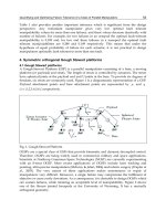
relationship (Fig.1). Because the climbing step ability is important factor as one of the most
fundamental mobility index (T. Inoh et al, 2005), moreover a climbing step experiment is
adopted by many researches as an evaluation experiment for mobility performance on
rough terrain. Thus this chapter shows sub-optimal number of crawler stages for connected
crawler robot which isn't cleared, through demonstrating the relationship between the
number of stages and maximum climb-able step height. After that, it proposes the actual
connected crawler robot, and show basic experimental result.
2. Deriving the Sub-optimal Number of Crawler Stages
In order to find sub-optimal number of crawler stages, we derive the maximum climb-able
step height of n-stages crawler (n=2~10). In this derivation, there is an optimization problem
for the joint motions. Because, if the joint can't realize suitable motion for the step, it might
be impossible to exercise climbing ability which the mechanism has. Therefore, the
optimized joint motions for the step are required. We set the environment to one step (Fig.
1), and then we try to solve the motion planning of each joint and derive the maximum
climb-able step height.
Connected Crawler Robot-Design and Motion Planning for Climbing a Step
405
ᨴ
ᨶ
h
Fig. 1. The assumed case
The motions of climbing a step are divided into 2 phases which shown in Fig.2.
1. Lifting up crawlers phase
This motion is strongly influenced by friction forces, contact forces and impact forces
between environments and crawlers.
2. Passing over phase
In order to generate a crock wise moment at the point of edge of the step and crawlers,
the robot has to change its posture. This motion is strongly influenced by friction,
balance of centre of gravity of the robot and inertia.
Phase 1
Phase 2
Fig. 2. The phases of climbing up a step
In each phase, changing the robot’s posture is important. If the robot can not lift up the body
as high as possible in Phase 1, the maximum climb-able step height can not be derived.
Even if the robot can lift up the body as high as possible in Phase 1, if the robot can not
generate the clock wise moment at the point of step edge, the climbing up a step can not be
realized. Therefore, it is need to consider not only the moment in phase 2 but also both of
Phase 1 and Phase 2. The maximum climb-able step height is distinguished by changes of
postures. That is to say, the problem of driving the maximum climb-able step height is the
optimization problem of each joint motion. If the each joint can not realize suitable motion to
Climbing & Walking Robots, Towards New Applications
406
the environment, it is impossible to exercise the ability of step climbing of the robot as
maximally as possible. Thus the each joint motion is required to realize the suitable motion
to the environment. But it is almost impossible to solve this problem by using analytical
methods, because the amount of patterns of changing postures (from Phase 1 to Phase 2)
becomes fatness by increasing the number of crawler stages. Thus the motion of each joint is
required to be derived by using a certain searching method. However, the round robin-like
searching method isn't so realistic, because the amount of searching becomes fat and
calculation time becomes enormous.
Therefore, we propose the following idea as one of the approach to solve this problem. If
certain approximate function can express an optimal joint motion in a few parameters, the
required joint motion can be derived in shorter time than a round robin-like search.
Therefore we try to express each joint angle function by using approximate function and
search the parameters in this function. Thus the problem of the parameter searching can be
substituted for the problem of the trajectory searching.
Moreover the robot has to change its posture with taking into interactions with environment,
in order to climb a maximum step height.
2.1 Proposed Method
In previous section, we described each joint motion are determined by certain approximate
function, and to search parameters in this approximate function. In the following parts, we
will mention the approximate function and how to search parameters, and show the method
to derive maximum climb-able step height.
2.1.1 The Approximate Function
There are n-order approximation, a tailor progression, a Fourier series, a spline function,
and so on, as an available approximate function. The approximate function must be possible
to differentiate twice, so as to find an angular velocity and angular acceleration. It is also
required that the function is periodic, and has a few parameters, and contains boundary
conditions. Therefore, Fourier series is useful function to satisfy these conditions (Y. Yokose
et al, 2004) . Thus, Fourier series approximates a joint angle functions. And the equation (1)
is Fourier series for this approximation,
¦¦
+=
==
j
i
i
j
i
in
tʌ
T
i
ȕtʌ
T
i
Įtș
00
2sin2cos)(
(1)
Here, n means the number of joints, j refers to the number of order of Fourier series, T
means the period. ǂ
i
, ǃ
i
, T are parameters which are searched.
2.1.2 Searching for Parameters in the Fourier Series
Searching for each coefficient and period in the Fourier series corresponds to the problem
which is to derive the optimized answer in a wide area. There are many approaches to solve
such optimization problems. Many researches proposed to use GA for such a problem
(Mohammed, 1997) ~ (S. Kawaji et al, 2001). Because, GA is able to find comparatively an
excellent answer in the utility time, and fit various problems. Therefore this chapter also
Connected Crawler Robot-Design and Motion Planning for Climbing a Step
407
adopts GA to search unknown coefficients in the Fourier series. We use simple GA (S.
Kobayashi et al, 1995), and set following parameters (Table. 1).
Number of chromosomes 10
Gene Length for one coefficient[bit] 10
Crossover rate [%] 25
Mutation rate[%] 1
Table 1. Parameters of GA
We also set the equation (2) to evaluate the chromosomes.
1000
1
11
¦¦
+
++=
==
n
i
n
i
ii
zx
t
hE
(2)
Here, h is the step height which the robot could climb up, t is the time for climbing up a step.
Then, it is understood that the evaluation is high when the robot could higher step in shorter
time. On the other hand, when the robot couldn't climb a step, we set h=0, t=100 as a penalty.
However, in these conditions, the evaluation of gene which couldn't climb up a step
becomes equal, and it makes difficult to execute crossover. Therefore the third clause of the
equation (1.2) exists as the valuation item. Here, x
n
, z
n
are the centre of gravity coordinates of
each stage. Thousand in the denominator is numerical value to scale it 1000 down .
2.1.3 The Method to Derive the Maximum Climb-able Step Height
In order to evaluate gene, we have to acquire appropriate position of centre of gravity in
each stage and distinguish whether the robot could climb or not. Because mobility
performance of the mobile mechanism concerns with topography characteristic closely, the
consideration of the interaction with the environment is very important. Therefore we
must consider dynamics and an interaction between robot and environment, for appropriate
acquisition of centre of gravity position and distinction of climbing. Thus we adopt
ODE(Open Dynamics Engine)(R. Smith) to calculate these values. ODE is open source
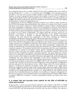
software, and is adopted by many robotic simulators to calculate dynamics. We derived
maximum climb-able step height by integrating ODE and GA. The calculation System is
shown in Fig.3.
ODEGA
˞ ,˟ ,T
Crossover
Mutation
Evolution
˥
n(t)
: joint angles, h : step height
Evaluation
Fig. 3. Proposed simulation system
Climbing & Walking Robots, Towards New Applications
408
GA gives joint angles and step height, and ODE calculate dynamics. After that, ODE
distinguishes whether the robot could climb or not, and returns the evaluation to GA. GA
makes a gene evolve, and optimizes joint angle function. Then the robot can climb higher
step in shorter time. A robot is considered to climb a step, when all centres of gravity in each
stage are higher than the height of the step h and it is on the right of A in Fig1.
2.2 Deriving the Maximum Climb-able Step Height of n-Stages
In this part, we derive maximum step height of n-stages based on the above mentioned
method. We set the conditions and assumption as follows.
Each initial joint angle is set 0.0[rad], and the range is -2.0ᨺ2.0[rad]. The range of Fourier
coefficients is -2.0ᨺ2.0. The range of Fourier series period T is 10ᨺ60[sec], and the order of
Fourier Series is 5. The initial genes are determined randomly. The specifications of the
connected crawler robots are shown in Table. 2 and Fig. 4. Other conditions are as follows.
Total length L [m] 2
Total mass M [kg] 2
Radius of the sprocket [m] 0.1
Table. 2. Parameters of the connected crawler robot
L [m]
M/2 [kg]M/2 [k g]
M/3 [kg] M/3 [kg] M/3 [kg]
M/n [kg]
M/n [kg]
M/n [kg]
M/n [k g]
2 stages
3 stages
n-stages
Fig. 4. The dividing definition of the robot
z Each stage is divided in constant total length L by corresponding to the number of
links.
z The crawler velocity is constant 0.1[m/s].
z The actuators have enough torque for driving joints.
Connected Crawler Robot-Design and Motion Planning for Climbing a Step
409
The range of step height h is 0.5ᨺ2.0[m], because the total length of connected crawler is
L=2.0[m]. By using above conditions, the simulation is done which is 4 stages and the
number of generations is 500. Then the maximum climb-able step height is derived.
2.3 Results
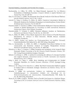
The results are shown in Fig.5 ~ Fig. 7.
In the Fig. 5, we can confirm that the robot could climb higher step when the number of
generations is increased, and time for climbing was shorten.
1XPEHURIW KH*HQHUDW LRQV
6W HSKHLJKW >P@
7LPH>VHF@
&OLPE DEOH VW HS KHLJKW
7LPHIRUFOLPELQJWKHVWHS
Fig. 5. Transition of the climb-able step height derived by GA (4 stages)
Fig.6 and Fig. 7 are snapshot when the robot is climbing up a step. In Fig.6, the height of
step is 0.9[m] and the number of generations is 56. In Fig.7, the height of step is 1.544[m]
(this is the maximum climb-able step height of 4 stages). From these figures, the climb-able
step height becomes higher and the motions of the joins are changed when the number of
generations is increased.
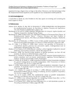
We also derive the maximum climb-able step height of 2 ~ 10 stages by using same method.
The results are shown in Fig.7. It is confirmed that the robot can climb higher step when the
number of generations is increased as well as the case of 4 stages, and maximum climb-able
step height of each link is derived.
Since the maximum climb-able step height of each stage has been shown in Fig.8, the
relationship between the number of stages and mobility performance of connected crawler
is demonstrated in Fig.9.
By this figure, it is able to be derived that the sub-optimal number of stages for connected
crawler is 5. Because it is turned out that the mobility performance is saturated more than 5
stages. Thus we can get the answer against the question that how many crawler stages
should be connected, namely that is 5 stages.
Climbing & Walking Robots, Towards New Applications
410
Fig. 6. Connected Crawler robot climb the step by using sub-optimized joint motion by GA
(4 stages, h=0.9 m, 56 generations)
Fig. 7. Connected Crawler robot climb the step by using sub-optimized joint motion by GA
(4 stages, h=1.544 m, 500 generations)
Connected Crawler Robot-Design and Motion Planning for Climbing a Step
411
1XPEHURI*HQHUDW LRQV
6WHS+HLJKW>P@
VW DJHV
VW DJHV
VW DJHV
VW DJHV
VW DJHV
VW DJHV
VW DJHV
VW DJHV
VW DJHV
Fig. 8. Transition of the climb-able step height derived by GA (2 ~ 10 stages)
1XPEHURIVWD
J
HV
6WHS+HLJKW>P@
Fig. 9. Relationship between the number of stages and climb-able step height
Climbing & Walking Robots, Towards New Applications
412
3. Constructing the Prototype
In the previous section, we have been able to obtain the sub-optimal number of crawler
stages, that is 5. Based on this conclusion, we have designed and developed the prototype of
connected crawler robot. It is shown in Fig. 10. The length is 0.59 m, width is 0.130 m, mass
is 1.28 kg.
0.59[m]
0.13[m]
Fig. 10. Prototype of connected crawler robot
3.1 Mechanical Structure
Our mechanism has 5 connected stages with the motor-driven crawler tracks on each side
(Fig. 11). RC-servo motors are used for driving joints between the stages. The left and right
crawlers are driven by 4 DC motors independently, while the 5 crawlers on each side are
driven by a motor simultaneously. The output of each motor is transmitted to the sprockets
of the three or two crawlers through several gears (Fig.12).
Connected Crawler Robot-Design and Motion Planning for Climbing a Step
413
RC servo for joints
Motors for crawler
Fig. 11. The driving structure (Color indicates driving relationship between motors and
crawlers)
Fig. 12. Transmission of motor outputs to the crawlers
3.2 Control Structure
The control architecture is hierarchical structure by connecting master controller and servo
unit (Fig .13, and Fig. 14).
The servo units control low level task: crawler velocity and joint angle by PID control law.
Each servo unit consists of one microcontroller (PIC16F873) and 2 DC motor drivers
(TA8440H). One microcontroller is installed to control two RC-servo units for the joint
control, where RC-servo is controlled only by PWM signal. Master controller controls high
level task: such as calculating robot trajectory. Table.3 shows the communication data
format. The command sent by master controller consists of 3 bytes. First byte indicates mode
ID and motor ID. The mode ID distinguishes 2 kinds of control modes: position control and
velocity control. The motor ID is used for selecting motor to control.
Second byte shows the data depends on control modes. The third byte is checksum.
Fig. 13. The control system