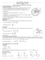
Single lens multi ocular stereovision using prism 1 4
Bạn đang xem bản rút gọn của tài liệu. Xem và tải ngay bản đầy đủ của tài liệu tại đây (1.98 MB, 59 trang )
i
ACKNOWLEDGEMENT
The author would like to express his most sincere appreciation to:
Associate Professor Kah Bin LIM, the supervisor of my Ph.D. study, for
giving me such an interesting and fruitful project to improve and demonstrate my
ability, and for his continuous supervision and valuable foresight and insight on this
project.
Mr. Voon Pong LEE, for his excellent early contribution on single-lens
stereovision using mirrors and initiation on single-lens stereovision using biprism
(2F-filter); and Mr. Raymond Lye Choon NG, for his cooperation on the preliminary
discussion on binocular stereovision using biprism.
Mr. Yee, Mrs. Ooi, Ms. Tshin, Miss Hamidah and Mr. Zhang and all the staff
in Control and Mechatronics Laboratory of the Mechanical Engineering Department,
for their kind support.
All colleagues and friends in Control and Mechatronics Laboratory, with
whom this project has become such a meaningful and memorable experience.
ii
TABLE OF CONTENT
ACKNOWLEDGEMENT I
TABLE OF CONTENT II
SUMMARY V
LIST OF TABLES VII
LIST OF FIGURES VIII
LIST OF SYMBOLS X
CHAPTER 1.
INTRODUCTION 1
CHAPTER 2.
LITERATURE REVIEW 5
2.1
C
ONVENTIONAL
T
WO
C
AMERA
S
TEREOVISION
T
ECHNIQUE
5
2.1.1
S
TEREOVISION
U
SING
T
WO
C
AMERAS
5
2.1.2
A
R
EVIEW ON
C
AMERA
C
ALIBRATION
T
ECHNIQUE
7
2.2
T
HE
S
INGLE
-L
ENS
S
TEREOVISION
T
ECHNIQUE
8
2.2.1
S
INGLE
-
LENS
S
TEREOVISION
S
YSTEMS
U
SING
O
PTICAL
D
EVICES
9
2.2.2
S
INGLE
-
LENS
S
TEREOVISION
S
YSTEM
U
SING KNOWN CUES
11
CHAPTER 3.
CAMERA CALIBRATION 15
CHAPTER 4.
SINGLE-LENS BINOCULAR STEREO-VISION 20
4.1
A
NALYSIS OF
V
IRTUAL
S
TEREOVISION
S
YSTEM
21
iii
4.1.1
F
ORMATION OF
V
IRTUAL
C
AMERAS
21
4.1.2
D
ETERMINING THE
V
IRTUAL
C
AMERAS
B
ASED ON
C
ALIBRATION
24
4.1.3
D
ETERMINING THE
V
IRTUAL
C
AMERAS
B
ASED ON
G
EOMETRICAL
A
NALYSIS OF
R
AY
S
KETCHING
27
4.2
E
XPERIMENT
35
4.2.1
E
XPERIMENTAL
S
ETUP
35
4.2.2
E
XPERIMENTAL
P
ROCEDURES
37
4.2.3
E
XPERIMENT
R
ESULTS
39
4.3
D
ISCUSSION
41
4.3.1
F
IELD OF
V
IEW
:
C
ONVERGENCE AND
D
IVERGENCE
41
4.3.2
E
RROR
A
NALYSIS FOR THE
G
EOMETRICAL
A
NALYSIS BASED
A
PPROACH
45
4.4
S
UMMARY
49
CHAPTER 5.
SINGLE-LENS TRINOCULAR STEREO-VISION 50
5.1
V
IRTUAL
C
AMERA
G
ENERATION
53
5.1.1
D
ETERMINING THE
V
IRTUAL
C
AMERAS BY
C
ALIBRATION
56
5.1.2
D
ETERMINING THE
V
IRTUAL
C
AMERAS BY
G
EOMETRICAL
A
NALYSIS OF
R
AY
S
KETCHING
60
5.1.2.1
The basic idea 61
5.1.2.2
Detailed description 65
5.2
E
XPERIMENT AND
D
ISCUSSION
89
5.3
S
UMMARY
92
CHAPTER 6.
SINGLE-LENS MULTI-OCULAR STEREOVISION 94
6.1
V
IRTUAL
C
AMERA
G
ENERATION
96
6.1.1
D
ETERMINING THE
V
IRTUAL
C
AMERAS BY
C
ALIBRATION
99
iv
6.1.2
D
ETERMINING THE
V
IRTUAL
C
AMERA BY
G
EOMETRICAL
A
NALYSIS OF
R
AY
S
KETCHING
104
6.2
E
XPERIMENT AND
D
ISCUSSION
109
6.3
S
UMMARY
113
CHAPTER 7.
CONCLUSION 115
CHAPTER 8.
FUTURE WORK 118
BIBLIOGRAPHY 120
APPENDICES 129
A
E
PIPOLAR
C
ONSTRAINTS
129
B
A
S
IMPLE
C
ALIBRATION
T
ECHNIQUE
138
C
G
EOMETRY
S
TUDY OF
3F
F
ILTER
141
v
SUMMARY
This thesis investigated a passive single-lens stereovision system using prism
(filter). Each image captured by this system is split into multiple different sub-
images and these sub-images are taken as images simultaneously captured by one
group of virtual cameras which are generated by the prism. Hence this system is able
to obtain multiple different views of the same scene using a single camera in one
shoot. The differences among these views, called disparities, are exploited to
perform depth recovery. This system can also be called a virtual stereovision system
corresponding to a virtual camera concept. According to the numbers of virtual
cameras generated, binocular stereovision system, trinocular stereovision system and
multi-ocular stereovision system are discussed separately.
Two different approaches are developed to understand and model this system:
one based on a camera calibration technique and another based on geometrical
analysis of ray sketching. The latter approach requires no complex camera
calibration, thus saving a large implementation effort without compromising accuracy.
One real system is implemented and experiments are designed and conducted
to test this concept. The result shows that both approaches are effective.
While this stereovision system has the advantages of low cost, compactness,
simultaneous image capturing, no camera synchronization problem, etc, it has the
limitation of small baseline due to the dimension of prisms used. Hence this system
is more suitable for close-range stereovision.
To our knowledge, the approaches developed in this thesis to study and
implement the single-lens binocular stereovision system are novel. Furthermore, the
designs of the single-lens trinocular and multi-ocular stereovision systems and the
vi
approaches used to understanding these two systems that are reported in this thesis
are novel.
Parts of this thesis have been previously published in papers.
vii
LIST OF TABLES
T
ABLE
4.1
R
ECOVERED DEPTH BY BINOCULAR STEREOVISION
,
λ
=
40
MM
41
T
ABLE
5.1
R
ECOVERED DEPTH BY TRINOCULAR STEREOVISION
,
λ
=
40
MM
93
T
ABLE
6.1
R
ECOVERED DEPTH BY MULTI
-
OUCLAR STEREOVISION
,
4
FACE FILTER
,
λ=45
MM
113
viii
LIST OF FIGURES
F
IGURE
2.1
M
ODELING OF TWO
-
CAMERA STEREOVISION SYSTEM
6
F
IGURE
2.2
T
HE CONCEPT OF EPIPOLAR LINE AND EPIPOLAR PLANE
7
F
IGURE
2.3
A
SINGLE
-
LENS STEREOVISION SYSTEM USING A GLASS PLATE
9
F
IGURE
2.4
A
SINGLE
-
LENS STEREOVISION SYSTEM USING THREE MIRRORS
10
F
IGURE
2.5
A
SINGLE
-
LENS STEREOVISION SYSTEM USING TWO MIRRORS
11
F
IGURE
3.1
C
AMERA CALIBRATION MODELING
16
F
IGURE
4.1
S
INGLE
-
LENS STEREOVISION SYSTEM USING A BIPRISM
22
F
IGURE
4.2
G
ENERATION OF VIRTUAL CAMERAS USING A BIPRISM
(
TOP VIEW
) 23
F
IGURE
4.3
R
AY MAP OF VIRTUAL
-
CAMERA CONFIGURATION
31
F
IGURE
4.4
S
YSTEM SETUP
36
F
IGURE
4.5
C
ALIBRATION BOARD
36
F
IGURE
4.6
C
ALIBRATION OF REAL CAMERA
37
F
IGURE
4.7
C
ALIBRATION OF VIRTUAL CAMERA
38
F
IGURE
4.8
D
ISPARITY
I
NFORMATION
39
F
IGURE
4.9
F
IELD OF VIEW
:
CONVERGENT SYSTEM
(ω
′
1
<
γ) 43
F
IGURE
4.10
F
IELD OF VIEW
:
DIVERGENT SYSTEM
(ω
′
1
>
2γ) 43
F
IGURE
4.11
F
IELD OF VIEW
:
DIVERGENT SYSTEM
(γ
<
ω
′
1
<
2γ) 44
F
IGURE
4.12
A
CASE OF CONVERGENT FIELD OF VIEW
44
F
IGURE
5.1
P
OSITIONING A
3F
FILTER IN FRONT OF A
CCD
CAMERA
55
F
IGURE
5.2
O
NE IMAGE CAPTURED BY THE SINGLE
-
LENS TRINOCULAR SYSTEM
55
F
IGURE
5.3
P
OSITION RELATIONSHIP BETWEEN REAL CAMERA AND
3F
FILTER
64
F
IGURE
5.4
S
YMBOLIC
I
LLUSTRATION OF VIRTUAL CAMERA MODELING USING GEOMETRICAL ANALYSIS
65
F
IGURE
5.5
W
ORKFLOW OF DETERMINING THE VIRTUAL CAMERA VIA GEOMETRICAL ANALYSIS
68
F
IGURE
5.6
P
LANE
PMN 71
F
IGURE
5.7
T
EMPORARY COORDINATE SYSTEM
T
AND
T
′
USED IN FINDING LINE
MN 73
F
IGURE
5.8
P
LANE
LNM 76
F
IGURE
5.9
T
EMPORARY COORDINATE SYSTEM
R
AND
R
′
USED IN FINDING LINE
NL 77
ix
F
IGURE
5.10
P
LANE
KJS 79
F
IGURE
5.11
I
LLUSTRATION OF THE SHORTEST SEGMENT CONNECTING TWO NON
-
INTERSECTING
,
AND
NON
-
PARALLEL LINES
82
F
IGURE
5.12
P
LANE
F
′
P
′
K
′
84
F
IGURE
5.13
C
ALIBRATION OF VIRTUAL CAMERAS
91
F
IGURE
6.1
S
YMBOLIC ILLUSTRATIONS OF MULTI
-
FACE FILTERS WITH
4
AND
5
FACES
97
F
IGURE
6.2
O
NE IMAGE CAPTURED BY THE SINGLE
-
LENS MULTI
-
OCULAR SYSTEM
(4
FACES
) 99
F
IGURE
6.3
C
ALIBRATION OF VIRTUAL CAMERAS
(4
FACES FILTER USED
) 112
F
IGURE
A.
1
E
PIPOLAR CONSTRAINT
130
F
IGURE
A.
2
E
PIPOLAR CONSTRAINT
(
USING DIFFERENT CAMERA MODE
) 131
F
IGURE
A.
3
I
LLUSTRATIONS OF
E
PIPOLAR
C
ONSTRAINTS IN
T
RINOCULAR
S
TEREOVISION
136
F
IGURE
A.
4
A
SIMPLE PIN
-
HOLE CAMERA MODEL
(
SIDE VIEW
) 138
F
IGURE
A.
5
A
SIMPLE PIN
-
HOLE CAMERA MODEL WITH TWO CROSSING OBJECT LINES
139
F
IGURE
A.
6
S
YMBOLIC ILLUSTRATION OF
3F
FILTER STRUCTURE
142
F
IGURE
A.
7
3F
FILTER
3D
STRUCTURE
,
WITH FRONT AND SIDE VIEW
143
x
LIST OF SYMBOLS
λ
= B
ASELINE
,
I
.
E
.
THE DISTANCE BETWEEN THE TWO CAMERA OPTICAL CENTRES
γ = T
HE ANGLE BETWEEN TWO CAMERA OPTICAL AXES
f = E
FFECTIVE REAL CAMERA FOCAL LENGTH
f
′
= E
FFECTIVE REAL VIRTUAL CAMERA FOCAL LENGTH
N
R
= R
EFLECTIVE INDEX OF PRISM
N
CX
= N
UMBER OF COLUMNS OF SENSOR ELEMENTS IN X
-
DIRECTION IN THE
CCD
N
CY
= N
UMBER OF COLUMNS OF SENSOR ELEMENTS IN Y
-
DIRECTION IN THE
CCD
N
FX
= N
UMBER OF PIXELS IN A LINE AS SAMPLED BY THE COMPUTER IN X
-
DIRECTION
N
FY
= N
UMBER OF PIXELS IN A LINE AS SAMPLED BY THE COMPUTER IN Y
-
DIRECTION
d
X
= D
ISTANCE BETWEEN ADJACENT
CCD
ELEMENTS IN X
-
DIRECTION
d
Y
= D
ISTANCE BETWEEN ADJACENT
CCD
ELEMENTS IN Y
-
DIRECTION
ρ = Y
AW ANGLE
(
ROTATION ABOUT Y AXIS
)
ν = P
ITCH ANGLE
(
ROTATION ABOUT X AXIS
)
ζ = T
ILT ANGLE
(
ROTATION ABOUT Z AXIS
)
G = T
RANSLATION MATRIX
R = R
OTATION MATRIX
P = T
RANSFORMATION MATRIX
(x
w
,y
w
,z
w
)
=
W
ORLD
COORDINATE
S
YSTEM
(x
cam
,y
cam
,z
cam
) = C
AMERA
COORDINATE
S
YSTEM
k
1
,
k
2
=
C
AMERA LENS DISTORTION
COEFFICIENTS
1
CHAPTER 1. INTRODUCTION
Computer stereovision technique is now widely used cartography, object
recognition, detection, inspection, and mobile robot navigation, etc. A great amount
of comprehensive research has been devoted to this area in recent decades. Software
technology is also broadly used to enhance its functionality and expand its
application domain.
Marr [1] depicts 3D vision as follows: ‘Form an image (or a series of images)
of a scene, derive an accurate three-dimensional geometric description of the scene
and quantitatively determine the properties of the object in the scene’. This means
that 3D computer vision consists of three stages: Data Capturing, Reconstruction and
Interpretation.
Stereovision system usually employs two or multiple cameras to capture
different views of a scene. When a point in the scene is projected into different
locations in each image plane, the difference in position of its projections is called the
disparity. The depth information of the point can be detected by using the properties
of individual cameras, geometric relationships between the cameras and the disparity,
yielding Reconstruction.
To effectively determine camera properties including its intrinsic and extrinsic
parameters, various camera calibration techniques have been developed. Camera
calibration usually requires accurate calibration patterns and dedicated software. In
addition, the use of two or multiple cameras results in high cost, difficulty in the
system setup and the camera synchronization problem. To avoid and or alleviate
these problems, a group of techniques called single-lens stereovision have been
developed.
2
The correspondence search in computer vision is to determine the pixels
corresponding to the same object point in different views acquired by the cameras
from different view angles of the same scene. Correspondence is problematic
because of occlusion, repeated patterns, image noise, poor illumination and image
quality, high computing load, etc. Current techniques often used in correspondence
searching include various geometrical constraints, correlation based analysis and
feature based analysis. Trinocular stereovision enables to check the hypothesized
correspondence points using additional epipolar constraints. However the extra
camera increases difficulty of system implementation, camera calibration and
synchronization.
This thesis presents our investigation of a single-lens stereovision using prism.
Though only one single CCD camera is used, this vision system is able to capture
multiple views (two, three or more views) of the same scene simultaneously and
these views can be taken as the images captured by virtual cameras which are
generated by the prism. The disparities among these views are exploited to perform
depth recovery like usual stereovision systems.
This system can be further categorized into three types according to different
numbers of virtual cameras generated: single-lens binocular stereovision system,
single-lens trinocular stereovision system and single-lens multi-ocular stereovision
system which will be discussed separately.
Firstly the single-lens binocular stereovision system is presented, followed by
the description on trinocular stereovision system which combines the advantages of
the single-lens stereovision and the trinocular stereovision. Finally, the
understanding of this single-lens trinocular stereovision is generalized and a single-
lens multi-ocular stereovision system is created.
3
The advantages of this single-lens stereovision system are obvious. As
compared to common two or multiple camera stereovision systems, it has a more
compact setup, lower cost, simpler implementation process, easier camera
synchronization since only one camera is used, and also simultaneous image
capturing without any complicated hardware, etc. Moreover this is a passive vision
system and it does not require any active assistance such as structured illumination or
any additional visual cues to be provided by the system nor the environment. Finally,
the trinocular stereovision can facilitate the correspondence searching. These
advantages motivate the investigation of this system.
Two different approaches are developed to model the single-lens stereovision
system and in particular, its virtual cameras: one of them is based on a camera
calibration technique and the other one is based on geometrical analysis of ray
sketching. The first approach is of secondary importance as it involves cumbersome
calibration implementation and operation which can be avoided by the latter approach.
The geometrical analysis based approach provides an interesting way of
understanding the system as it gives much simpler system implementation with
acceptable accuracy in depth recovery.
One real system has been implemented and the experiments are carried out to
test the single-lens binocular, trinocular and multi-ocular stereovision systems and to
verify the validity of this system. The results can prove the effectiveness of the both
approaches used to model these systems. We believe that most of the work presented
in this thesis, including the way of modeling the single-lens binocular system and the
design of the single-lens trinocular and multi-ocular systems are novel, and we also
believe that this system are practically useful in science and industrial area.
4
The thesis is organized as follows: Chapter 2 gives a literature review on
single-lens stereovision technique; Chapter 3 describes the theory of calibration
technique which is used by this system; Chapter 4 describes the single-lens binocular
stereovision system; Chapter 5 and 6 describe the single-lens trinocular stereovision
system and the single-lens multi-ocular stereovision system, respectively; finally
Chapter 7 and Chapter 8 give the conclusion and comments on future work. More
information can be found in the Appendices.
5
CHAPTER 2. LITERATURE REVIEW
This section firstly gives a brief review on the theories of computer
stereovision and camera calibration that are the basic concepts used through the thesis,
and then presents a detailed review on the single-lens stereovision techniques.
2.1 Conventional Two Camera Stereovision Technique
2.1.1 Stereovision Using Two Cameras
A conventional stereovision process used in depth recovery can be
summarized into three following major steps [2]: (1) detection of features in each
image, (2) matching of features between the images under certain geometric and
other stereo correspondence constraints, and (3) calculation of depth using the
disparity values and the geometric parameters of the imaging configuration. A
simple canonical stereo system using two parallel cameras is modeled as shown in
Figure 2.1.
The geometry of the projections leads to the recovery of the coordinate of the
scene point:
rlrl
rl
rl
rl
xx
f
z
xx
yy
y
xx
xx
x
−
=
−
+
=
−
+
=
λ
λ
λ
;
2
)(
;
2
)(
,
(2.1)
where λ is the length of the baseline connecting the two optical centers and f is the
focal length of each camera, and the disparity is (x
l
– x
r
). The remaining symbols are
defined in Figure 2.1. In this setup, the focal lengths of the two cameras are assumed
to be the same.
6
Figure 2.1 Modeling of two-camera stereovision system
A useful concept often used in stereovision is the epipolar line, which
increases the efficiency of correspondence search between two image planes. The
essence of this theory is: given an object point p and its projection in the left image p
l
,
then the corresponding right image point p
r
must be located on the corresponding
epipolar line. The epipolar line is formed by the intersection of the epipolar plane
with the right image plane. The epipolar plane is defined as the plane that passes
through the points p
l
, C
l
and C
r
, where C
l
and C
r
are the optical centers of the left and
right camera lens respectively, as shown in Figure 2.2. A more detailed review and a
discussion on its mathematics for the consideration of implementation are given in
Appendix A.
Right Image plane
Left Image plane
Right Optic Centre
Left Optic Centre
x
l
x
r
y
r
y
l
p
r
( x
r,
y
r
)
p
l
( x
l
, y
l
)
f
P=(x,y,z)
x
y
z
λ
/2
λ
/2
7
Figure 2.2 The concept of epipolar line and epipolar plane
2.1.2 A Review on Camera Calibration Technique
The purpose for camera calibration is to find the relationship between the
camera image plane coordinates and the world coordinates. This relationship is
defined by the camera intrinsic parameters, such as camera focal length and lens
distortion, and the extrinsic parameters, such as relative position and orientation with
respect to the external world. The essence of a simple calibration technique can be
described as: a world point w,
T
www
zyxw ][= , can be mapped onto an image
point c,
[
]
T
hhhh
ccccc
4321
= , by a series of translations and rotations [3]:
Right image
Left image
Epipolar line
C
l
C
r
P
Optical axis
Optical axis
P
l
P
r
Epipolar plane
8
,
1
or
44434241
34333231
24232221
14131211
4
3
2
1
=
=
w
w
w
h
h
h
h
hh
z
y
x
aaaa
aaaa
aaaa
aaaa
c
c
c
c
PRGwc
(2.2)
where G is the translation matrix, R is the rotation matrix and P is the perspective
transformation matrix, and c
h
and w
h
are in homogeneous coordinates.
G, R and P contain terms which include the intrinsic parameters and extrinsic
parameters, which are important in the characterization of a machine vision system.
Reference [3] gives details of the calibration procedures. The matrix containing a
ij
, i
= 1 to 4, j = 1 to 4, is known as the calibration matrix.
Due to the importance of stereovision, a great amount of research work has
been devoted to this topic. A concise introduction of stereovision can be found in the
book by Trucco and Verri [4]. More explanations and discussions can be found in
the books by Faugeras [5], Hartley et al. [6], and Sonka et al. [7].
2.2 The Single-Lens Stereovision Technique
Many different single-lens stereovision techniques have been developed
because of the significant potential advantages of this technique over conventional
two or multiple camera stereovision systems. These techniques can be classified into
two groups. The techniques of the first group use some optical devices, such as
mirrors to achieve the stereovision effect; the techniques of the second group exploit
some known cues from the vision system itself such as known camera movement or
from its environment such as known illumination conditions. Both categories rely on
9
triangulation knowledge to explain the generation of their stereovision effect. They
are separately introduced in the following sections.
Passive vs. active methods is another possible criterion to classify these
techniques; simultaneous stereo images (or their equivalents) capturing or non-
simultaneous stereo images capturing can also be a criterion.
Here the discussion is not extended to the techniques of stereo from
shading/pictorial information and photometric stereo.
2.2.1 Single-lens Stereovision Systems Using Optical Devices
Nishimoto and Shirai [8] proposed a single-lens stereovision system which
can obtain stereo images as shown in Figure 2.3. In this system a glass plate is
positioned in front of the camera so that its rotation will cause the optical axe of the
camera slightly shifted because of its refraction. Hence stereo image pairs can be
captured but with small disparities.
Figure 2.3 A single-lens stereovision system using a glass plate
Mirrors are often used to assist in achieving single-lens stereovision effect.
Teoh and Zhang [9] described a single-lens stereo-camera system which employs
three mirrors as shown in Figure 2.4. Two mirrors are positioned to at a 45° relative
to the optical axis of the camera, and a third mirror is positioned in front of the
10
camera lens and can be rotated to be parallel to either of the fixed mirrors in sequence
and two different images are thus obtained from one static scene.
Figure 2.4 A single-lens stereovision system using three mirrors
The systems described above require the camera to take two separate shots to
obtain one pair of stereo images, their applications are probably limited to static
scene or slow changing environment only (even though fast rotation speed of the
glass or mirrors reduces the negative effect of this limitation). Gosthasby and Gruver
[10] described another mirror-based single-lens stereovision system as shown in
Figure 2.5, which can overcome this problem. The acquired images are reflected by
the mirrors and transformation processes of these images are needed before carrying
out the correspondence and depth measurement as in a normal two camera
stereovision system.
And one system which has movable mirror components to control its view
scope is introduced by Inaba et al. [11]. Nene and Nayar [12] performed further
analysis of this kind of mirror based stereovision system. In their study a single
camera is positioned to point towards not only planar mirrors, but also hyperboloidal,
ellipsoidal and paraboloidal mirrors. By using non-planar reflecting surfaces, such as
hyperboloids and paraboloids, a wide field of view (FOV) can be achieved.
11
Figure 2.5 A single-lens stereovision system using two mirrors
Compared with the design of capturing images in mirrors only, the design of
capturing images in mirrors plus the direct object image of the object were also
proposed by some researchers. Zhang and Tsui [13] proposed such an
implementation by positioning the mirror beside the object. Francois et al. [14]
further refined the concepts of stereovision from a single perspective of a mirror
symmetric scene and concluded that a mirror symmetric scene is equivalent to
observing scene with two cameras and all traditional analysis tools of binocular
stereovision can be applied.
2.2.2 Single-lens Stereovision System Using Known Cues
A good example of this kind of method is by using known illuminations.
Segan et al. [15] designed a system which used a camera and a point light source to
track a user’s hand in 3-D space. The light source needed to be calibrated in this
system and the projections of the hand and its shadow were used as the cues to find
stereo information.
Another good method uses known geometry of the object in the scene as the
cue to recovery depth information. Nakazawa et al. [16] devised a method which
performed both camera calibration and measurement with an object whose feature
12
points were projected onto one image plane while moving the single camera by hand.
It required four coplanar points such as the corners of a sheet of A4-sized paper in the
scene as the cue. Another attempt using a similar approach was presented by Suzuki
et al. [17]. The most important cue used in their algorithm was the invariant relative
positions of the representative points of a rigid body.
Moore and Hayes [18] presented a simple method of tracking the position and
orientation of objects from a single camera by exploiting the perspective projection
model. Three coplanar points on the object need to be identified, which are the cues
for the stereos, and their distances from the camera lens are measured.
There are many other different techniques using camera movement as the cue
to retrieve the stereo information. In the work by LeGrand and Luo [19], an
estimation technique which retains the non-linear camera dynamics and provides an
accurate 3-D estimation of the positions of selected targets within the environment is
presented. When this method is applied to robot navigation, the key to this algorithm
is that during pursuit, the robot continuously takes centroid measurements of the
target and uses the estimation algorithm to calculate the target’s position. This
implies that the stereo information is generated from the motion information which is
acquired through the movement-sensor attached to the robot.
Adelson and Wang [20] described one method which achieves single-lens
stereovision effect using a concept called plenoptic camera. Their system retains the
structure by the light impinging on the camera sensor plane by placing a set of
miniature cameras formed by a pinhole array or a lenticular array. Cardillo et al. [21]
described another single-lens stereovision method which was based on the
investigation on the blurring effects of camera focusing. Another interesting example
13
is the work by Ye, et al [22]. In their work, they only use one sing camera with a
telecentric lens to captured stereo views of the IC chip by rotating the chip.
It can be seen that a great amount of attention and effort has been drawn to
single-lens stereovision technique. In Control and Mechatronics Laboratory of the
Department of Mechanical Engineering, NUS, continuous effort has been made into
single-lens stereovision. A mirror based binocular stereovision system was designed
successfully by Lee [25] a few years ago. A preliminary discussion on a biprism (2F-
filter) based binocular single-lens stereovision was done by Lee [25], Xiao [26] and
Ng [27], and recent and more comprehensive work is discussed in depth in this thesis.
In this thesis the newest approaches of understanding this kind of binocular
stereovision and also designs of trinocular and multi-ocular stereovision system are
presented, which are believed to be novel.
Lee and Kweon et al. [23][24] proposed a single-lens stereo system using one
biprism which has a similar setup of the binocular system that is presented in this
thesis, but in the aspect of the approaches used to understand such a system, readers
will see fundamental differences between the methods reported here and theirs, and
some differences are high-lighted in this thesis. Lee and Kweon assume an arbitrary
point in the view zone of this vision system is transformed into two virtual points in
3-D space, from which this system can be understood, and its equivalent stereo
system can be found, but the approaches reported in this thesis directly assume the
existence of two virtual cameras and determine them using the law of refraction (for
the approach using geometrical analysis of ray sketching). The two different
approaches give many different understandings of system properties including the
relationship between the image disparity and the depth. Moreover, this thesis also
shows that the traditional calibration technique is also a feasible way to determine
14
this system. Here, alternatives to understand such a system are also presented to
some details.
15
CHAPTER 3. CAMERA CALIBRATION
This chapter describes the basic theory of the camera calibration technique
used in this single-lens stereovision system. Camera calibration is a process to obtain
the camera intrinsic and extrinsic parameters. The intrinsic parameters are inherent in
a camera system, which normally include the effective focal length, lens distortion
coefficients, scaling factors and position and orientation of the coordinates of the
camera; the extrinsic parameters include the translation and orientation information
of the camera frame with reference to a specified world coordinate system. The
extrinsic parameters can be used to determine the relative position between two
cameras, which is an essential knowledge of a stereovision system. The classical
method of calibration solves the perspective transformation matrix which contains the
intrinsic and extrinsic information of interest. This is accomplished by associating an
enough number of known non-coplanar 3D world coordinates with their
corresponding 2D image coordinates captured by camera. These points are usually
obtained from a set of objects with known relative positions and dimensions in
camera view zone, and are called calibration patterns. A list of the works from the
pioneers and recent contributors on calibration techniques can be found in [31] - [37].
In our system, camera calibration is required to determine the real camera
properties and also the virtual cameras properties required by one of the approaches
used to model the system, which is presented in the following chapters.
The camera technique used here is based on the work by Tsai [37] with very
minor modification as this is a very well-known calibration method and is found to be
suitable to serve our purposes. A short description on this calibration technique is
given in this chapter with the emphasis on its coordinate system setup which is