John wiley sons rfid handbook fundamentals and applications in contactless smart cards and identification2003 finkenzeller
Bạn đang xem bản rút gọn của tài liệu. Xem và tải ngay bản đầy đủ của tài liệu tại đây (5.81 MB, 434 trang )
RFID Handbook: Fundamentals and Applications in Contactless Smart Cards and Identification,
Second Edition
Klaus Finkenzeller
Copyright 2003 John Wiley & Sons, Ltd.
ISBN: 0-470-84402-7
RFID
Handbook
Second Edition
RFID
Handbook
Fundamentals and Applications in Contactless Smart
Cards and Identification
Second Edition
Klaus Finkenzeller
Giesecke & Devrient GmbH, Munich, Germany
Translated by
Rachel Waddington
Member of the Institute of Translation and Interpreting
First published under the title RFID-Handbuch, 2 Auflage by Carl Hanser Verlag
Carl Hanser Verlag, Munich/FRG, 1999 All rights reserved
Authorized translation from the 2nd edition in the original German language
published by Carl Hanser Verlag, Munich/FRG
Copyright 2003
John Wiley & Sons Ltd, The Atrium, Southern Gate, Chichester,
West Sussex PO19 8SQ, England
Telephone (+44) 1243 779777
Email (for orders and customer service enquiries):
Visit our Home Page on www.wileyeurope.com or www.wiley.com
All Rights Reserved. No part of this publication may be reproduced, stored in a retrieval system or
transmitted in any form or by any means, electronic, mechanical, photocopying, recording, scanning or
otherwise, except under the terms of the Copyright, Designs and Patents Act 1988 or under the terms of a
licence issued by the Copyright Licensing Agency Ltd, 90 Tottenham Court Road, London W1T 4LP,
UK, without the permission in writing of the Publisher. Requests to the Publisher should be addressed to
the Permissions Department, John Wiley & Sons Ltd, The Atrium, Southern Gate, Chichester, West
Sussex PO19 8SQ, England, or emailed to , or faxed to (+44) 1243 770571.
This publication is designed to provide accurate and authoritative information in regard to the subject
matter covered. It is sold on the understanding that the Publisher is not engaged in rendering professional
services. If professional advice or other expert assistance is required, the services of a competent
professional should be sought.
Other Wiley Editorial Offices
John Wiley & Sons Inc., 111 River Street, Hoboken, NJ 07030, USA
Jossey-Bass, 989 Market Street, San Francisco, CA 94103-1741, USA
Wiley-VCH Verlag GmbH, Boschstr. 12, D-69469 Weinheim, Germany
John Wiley & Sons Australia Ltd, 33 Park Road, Milton, Queensland 4064, Australia
John Wiley & Sons (Asia) Pte Ltd, 2 Clementi Loop #02-01, Jin Xing Distripark, Singapore 129809
John Wiley & Sons Canada Ltd, 22 Worcester Road, Etobicoke, Ontario, Canada M9W 1L1
Wiley also publishes its books in a variety of electronic formats. Some content that appears
in print may not be available in electronic books.
Library of Congress Cataloging-in-Publication Data
Finkenzeller, Klaus.
[RFID Handbuch. English]
RFID handbook : fundamentals and applications in contactless smart cards and
identifcation/Klaus Finkenzeller; translated by Rachel Waddington. — 2nd ed.
p. cm.
Includes bibliographical references and index.
ISBN 0-470-84402-7 (alk. paper)
1. Inventory control — Automation. 2. Radio frequency identification systems. 3. Smart.
cards. I. Title.
TS160.F5513 2003
658.7 87 — dc21
2002192439
British Library Cataloguing in Publication Data
A catalogue record for this book is available from the British Library
ISBN 0-470-84402-7
Typeset in 10/12pt Times by Laserwords Private Limited, Chennai, India
Printed and bound in Great Britain by Antony Rowe Ltd, Chippenham, Wiltshire
This book is printed on acid-free paper responsibly manufactured from sustainable forestry
in which at least two trees are planted for each one used for paper production.
Contents
PREFACE
LIST OF ABBREVIATIONS
1 Introduction
1.1 Automatic Identification Systems
1.1.1
1.1.2
1.1.3
1.1.4
1.1.5
Barcode systems
Optical character recognition
Biometric procedures
1.1.3.1 Voice identification
1.1.3.2 Fingerprinting procedures (dactyloscopy)
Smart cards
1.1.4.1 Memory cards
1.1.4.2 Microprocessor cards
RFID systems
1.2 A Comparison of Different ID Systems
1.3 Components of an RFID System
2 Differentiation Features of RFID Systems
2.1 Fundamental Differentiation Features
2.2 Transponder Construction Formats
2.2.1
2.2.2
2.2.3
2.2.4
2.2.5
2.2.6
2.2.7
2.2.8
2.2.9
2.2.10
Disks and coins
Glass housing
Plastic housing
Tool and gas bottle identification
Keys and key fobs
Clocks
ID-1 format, contactless smart cards
Smart label
Coil-on-chip
Other formats
2.3 Frequency, Range and Coupling
2.4 Information Processing in the Transponder
2.4.1
2.4.2
2.4.3
Low-end systems
Mid-range systems
High-end systems
2.5 Selection Criteria for RFID Systems
2.5.1
2.5.2
Operating frequency
Range
xiii
xv
1
2
2
3
4
4
4
5
5
6
6
7
7
11
11
13
13
14
14
15
17
18
18
19
20
21
22
23
23
24
25
25
26
26
CONTENTS
vi
2.5.3
2.5.4
Security requirements
Memory capacity
3 Fundamental Operating Principles
3.1 1-Bit Transponder
3.1.1
3.1.2
3.1.3
3.1.4
3.1.5
Radio frequency
Microwaves
Frequency divider
Electromagnetic types
Acoustomagnetic
3.2 Full and Half Duplex Procedure
3.2.1
3.2.2
3.2.3
3.2.4
3.2.5
Inductive coupling
3.2.1.1 Power supply to passive transponders
3.2.1.2 Data transfer transponder → reader
Electromagnetic backscatter coupling
3.2.2.1 Power supply to the transponder
3.2.2.2 Data transmission → reader
Close coupling
3.2.3.1 Power supply to the transponder
3.2.3.2 Data transfer transponder → reader
Electrical coupling
3.2.4.1 Power supply of passive transponders
3.2.4.2 Data transfer transponder → reader
Data transfer reader → transponder
3.3 Sequential Procedures
3.3.1
3.3.2
Inductive coupling
3.3.1.1 Power supply to the transponder
3.3.1.2 A comparison between FDX/HDX and SEQ systems
3.3.1.3 Data transmission transponder → reader
Surface acoustic wave transponder
4 Physical Principles of RFID Systems
4.1 Magnetic Field
4.1.1
4.1.2
4.1.3
4.1.4
4.1.5
4.1.6
4.1.7
4.1.8
Magnetic field strength H
4.1.1.1 Path of field strength H (x) in conductor loops
4.1.1.2 Optimal antenna diameter
Magnetic flux and magnetic flux density
Inductance L
4.1.3.1 Inductance of a conductor loop
Mutual inductance M
Coupling coefficient k
Faraday’s law
Resonance
Practical operation of the transponder
4.1.8.1 Power supply to the transponder
4.1.8.2 Voltage regulation
27
28
29
29
30
33
35
36
37
40
41
41
42
47
47
49
49
49
50
51
51
53
53
54
54
54
54
56
57
61
61
61
62
65
66
67
68
68
70
71
73
78
78
78
CONTENTS
vii
Interrogation field strength Hmin
4.1.9.1 Energy range of transponder systems
4.1.9.2 Interrogation zone of readers
4.1.10 Total transponder — reader system
4.1.10.1 Transformed transponder impedance Z ’T
4.1.10.2 Influencing variables of Z ’T
4.1.10.3 Load modulation
4.1.11 Measurement of system parameters
4.1.11.1 Measuring the coupling coefficient k
4.1.11.2 Measuring the transponder resonant frequency
4.1.12 Magnetic materials
4.1.12.1 Properties of magnetic materials and ferrite
4.1.12.2 Ferrite antennas in LF transponders
4.1.12.3 Ferrite shielding in a metallic environment
4.1.12.4 Fitting transponders in metal
4.1.9
4.2 Electromagnetic Waves
4.2.1
4.2.2
4.2.3
4.2.4
4.2.5
4.2.6
The generation of electromagnetic waves
4.2.1.1 Transition from near field to far field in conductor loops
Radiation density S
Characteristic wave impedance and field strength E
Polarisation of electromagnetic waves
4.2.4.1 Reflection of electromagnetic waves
Antennas
4.2.5.1 Gain and directional effect
4.2.5.2 EIRP and ERP
4.2.5.3 Input impedance
4.2.5.4 Effective aperture and scatter aperture
4.2.5.5 Effective length
4.2.5.6 Dipole antennas
4.2.5.7 Yagi–Uda antenna
4.2.5.8 Patch or microstrip antenna
4.2.5.9 Slot antennas
Practical operation of microwave transponders
4.2.6.1 Equivalent circuits of the transponder
4.2.6.2 Power supply of passive transponders
4.2.6.3 Power supply of active transponders
4.2.6.4 Reflection and cancellation
4.2.6.5 Sensitivity of the transponder
4.2.6.6 Modulated backscatter
4.2.6.7 Read range
4.3 Surface Waves
4.3.1
4.3.2
4.3.3
4.3.4
The creation of a surface wave
Reflection of a surface wave
Functional diagram of SAW transponders (Figure 4.95)
The sensor effect
4.3.4.1 Reflective delay lines
4.3.4.2 Resonant sensors
80
82
84
86
88
90
97
103
103
105
106
107
108
109
110
111
111
112
114
115
116
117
119
119
120
121
121
124
125
127
128
130
131
131
133
140
141
142
143
145
148
148
150
151
153
154
155
CONTENTS
viii
4.3.5
4.3.4.3 Impedance sensors
Switched sensors
5 Frequency Ranges and Radio Licensing Regulations
5.1 Frequency Ranges Used
5.1.1
5.1.2
5.1.3
5.1.4
5.1.5
5.1.6
5.1.7
5.1.8
5.1.9
5.1.10
5.1.11
5.1.12
Frequency range 9–135 kHz
Frequency range 6.78 MHz
Frequency range 13.56 MHz
Frequency range 27.125 MHz
Frequency range 40.680 MHz
Frequency range 433.920 MHz
Frequency range 869.0 MHz
Frequency range 915.0 MHz
Frequency range 2.45 GHz
Frequency range 5.8 GHz
Frequency range 24.125 GHz
Selection of a suitable frequency for inductively coupled RFID systems
5.2 European Licensing Regulations
5.2.1
5.2.2
5.2.3
5.2.4
CEPT/ERC REC 70-03
5.2.1.1 Annex 1: Non-specific short range devices
5.2.1.2 Annex 4: Railway applications
5.2.1.3 Annex 5: Road transport and traffic telematics
5.2.1.4 Annex 9: Inductive applications
5.2.1.5 Annex 11: RFID applications
5.2.1.6 Frequency range 868 MHz
EN 300 330: 9 kHz–25 MHz
5.2.2.1 Carrier power — limit values for H field transmitters
5.2.2.2 Spurious emissions
EN 300 220-1, EN 300 220-2
EN 300 440
5.3 National Licensing Regulations in Europe
5.3.1
Germany
5.4 National Licensing Regulations
5.4.1
5.4.2
USA
Future development: USA–Japan–Europe
6 Coding and Modulation
6.1 Coding in the Baseband
6.2 Digital Modulation Procedures
6.2.1
6.2.2
6.2.3
6.2.4
Amplitude shift keying (ASK)
2 FSK
2 PSK
Modulation procedures with subcarrier
7 Data Integrity
7.1 The Checksum Procedure
157
159
161
161
161
163
163
163
165
165
166
166
166
166
166
167
169
169
170
171
172
172
172
173
173
173
175
175
176
177
177
179
179
180
183
184
186
186
189
190
191
195
195
CONTENTS
7.1.1
7.1.2
7.1.3
ix
Parity checking
LRC procedure
CRC procedure
7.2 Multi-Access Procedures — Anticollision
7.2.1
7.2.2
7.2.3
7.2.4
Space division multiple access (SDMA)
Frequency domain multiple access (FDMA)
Time domain multiple access (TDMA)
Examples of anticollision procedures
7.2.4.1 ALOHA procedure
7.2.4.2 Slotted ALOHA procedure
7.2.4.3 Binary search algorithm
8 Data Security
8.1 Mutual Symmetrical Authentication
8.2 Authentication Using Derived Keys
8.3 Encrypted Data Transfer
8.3.1
Stream cipher
9 Standardisation
9.1 Animal Identification
9.1.1
9.1.2
9.1.3
ISO 11784 — Code structure
ISO 11785 — Technical concept
9.1.2.1 Requirements
9.1.2.2 Full/half duplex system
9.1.2.3 Sequential system
ISO 14223 — Advanced transponders
9.1.3.1 Part 1 — Air interface
9.1.3.2 Part 2 — Code and command structure
9.2 Contactless Smart Cards
9.2.1
9.2.2
9.2.3
9.2.4
ISO 10536 — Close coupling smart cards
9.2.1.1 Part 1 — Physical characteristics
9.2.1.2 Part 2 — Dimensions and locations of coupling areas
9.2.1.3 Part 3 — Electronic signals and reset procedures
9.2.1.4 Part 4 — Answer to reset and transmission protocols
ISO 14443 — Proximity coupling smart cards
9.2.2.1 Part 1 — Physical characteristics
9.2.2.2 Part 2 — Radio frequency interference
9.2.2.3 Part 3 — Initialisation and anticollision
9.2.2.4 Part 4 — Transmission protocols
ISO 15693 — Vicinity coupling smart cards
9.2.3.1 Part 1 — Physical characteristics
9.2.3.2 Part 2 — Air interface and initialisation
ISO 10373 — Test methods for smart cards
9.2.4.1 Part 4: Test procedures for close coupling smart cards
9.2.4.2 Part 6: Test procedures for proximity coupling smart cards
9.2.4.3 Part 7: Test procedure for vicinity coupling smart cards
195
196
197
200
202
204
205
206
206
208
212
221
221
223
224
225
229
229
229
230
230
232
232
233
233
234
236
237
238
238
238
239
240
240
240
245
251
256
256
256
260
261
261
264
CONTENTS
x
9.3 ISO 69873 — Data Carriers for Tools and Clamping Devices
9.4 ISO 10374 — Container Identification
9.5 VDI 4470 — Anti-theft Systems for Goods
9.5.1
9.5.2
Part 1 — Detection gates — inspection guidelines for customers
9.5.1.1 Ascertaining the false alarm rate
9.5.1.2 Ascertaining the detection rate
9.5.1.3 Forms in VDI 4470
Part 2 — Deactivation devices, inspection guidelines for customers
9.6 Item Management
9.6.1
9.6.2
ISO 18000 series
GTAG initiative
9.6.2.1 GTAG transport layer (physical layer)
9.6.2.2 GTAG communication and application layer
10 The Architecture of Electronic Data Carriers
10.1 Transponder with Memory Function
10.1.1 HF interface
10.1.1.1 Example circuit — load modulation with subcarrier
10.1.1.2 Example circuit — HF interface for ISO 14443 transponder
10.1.2 Address and security logic
10.1.2.1 State machine
10.1.3 Memory architecture
10.1.3.1 Read-only transponder
10.1.3.2 Writable transponder
10.1.3.3 Transponder with cryptological function
10.1.3.4 Segmented memory
10.1.3.5 MIFARE application directory
10.1.3.6 Dual port EEPROM
10.2 Microprocessors
10.2.1 Dual interface card
10.2.1.1 MIFARE plus
10.2.1.2 Modern concepts for the dual interface card
10.3 Memory Technology
10.3.1
10.3.2
10.3.3
10.3.4
RAM
EEPROM
FRAM
Performance comparison FRAM — EEPROM
10.4 Measuring Physical Variables
10.4.1 Transponder with sensor functions
10.4.2 Measurements using microwave transponders
10.4.3 Sensor effect in surface wave transponders
11 Readers
11.1 Data Flow in an Application
11.2 Components of a Reader
265
265
265
265
266
267
267
268
268
268
269
270
271
273
273
273
274
276
278
279
280
280
281
281
284
286
289
292
293
295
296
298
299
299
300
302
302
302
303
305
309
309
309
CONTENTS
xi
11.2.1 HF interface
11.2.1.1 Inductively coupled system, FDX/HDX
11.2.1.2 Microwave systems — half duplex
11.2.1.3 Sequential systems — SEQ
11.2.1.4 Microwave system for SAW transponders
11.2.2 Control unit
11.3 Low Cost Configuration — Reader IC U2270B
11.4 Connection of Antennas for Inductive Systems
11.4.1
11.4.2
11.4.3
Connection using current matching
Supply via coaxial cable
The influence of the Q factor
11.5 Reader Designs
11.5.1
11.5.2
11.5.3
OEM readers
Readers for industrial use
Portable readers
12 The Manufacture of Transponders and Contactless
Smart Cards
12.1 Glass and Plastic Transponders
12.1.1 Module manufacture
12.1.2 Semi-finished transponder
12.1.3 Completion
12.2 Contactless Smart Cards
12.2.1 Coil manufacture
12.2.2 Connection technique
12.2.3 Lamination
311
312
313
314
315
316
317
319
320
322
325
326
326
327
328
329
329
329
330
332
332
333
336
338
13 Example Applications
341
13.1 Contactless Smart Cards
13.2 Public Transport
341
342
343
344
344
344
345
346
346
347
347
349
350
354
354
356
13.2.1 The starting point
13.2.2 Requirements
13.2.2.1 Transaction time
13.2.2.2 Resistance to degradation, lifetime, convenience
13.2.3 Benefits of RFID systems
13.2.4 Fare systems using electronic payment
13.2.5 Market potential
13.2.6 Example projects
13.2.6.1 Korea — seoul
13.2.6.2 Germany — L¨uneburg, Oldenburg
13.2.6.3 EU Projects — ICARE and CALYPSO
13.3 Ticketing
13.3.1 Lufthansa miles & more card
13.3.2 Ski tickets
CONTENTS
xii
13.4 Access Control
13.4.1 Online systems
13.4.2 Offline systems
13.4.3 Transponders
13.5 Transport Systems
13.5.1
13.5.2
Eurobalise S21
International container transport
13.6 Animal Identification
13.6.1
13.6.2
Stock keeping
Carrier pigeon races
13.7 Electronic Immobilisation
13.7.1
13.7.2
13.7.3
The functionality of an immobilisation system
Brief success story
Predictions
13.8 Container Identification
13.8.1
13.8.2
Gas bottles and chemical containers
Waste disposal
13.9 Sporting Events
13.10 Industrial Automation
13.10.1 Tool identification
13.10.2 Industrial production
13.10.2.1 Benefits from the use of RFID systems
13.10.2.2 The selection of a suitable RFID system
13.10.2.3 Example projects
13.11 Medical Applications
14 Appendix
394
14.1 Contact Addresses, Associations and Technical Periodicals
14.1.1
14.1.2
14.1.3
Industrial associations
Technical journals
RFID on the internet
14.2 Relevant Standards and Regulations
14.2.1
Sources for standards and regulations
14.3 References
14.4 Printed Circuit Board Layouts
14.4.1
14.4.2
INDEX
357
357
358
360
361
361
363
364
364
367
371
372
375
376
376
376
378
379
381
381
385
387
388
389
392
Test card in accordance with ISO 14443
Field generator coil
394
394
398
399
400
405
406
412
412
413
419
Preface to the
2nd Edition
This book is aimed at an extremely wide range of readers. First and foremost it is
intended for students and engineers who find themselves confronted with RFID technology for the first time. A few basic chapters are provided for this audience describing
the functionality of RFID technology and the physical and IT-related principles underlying this field. The book is also intended for practitioners who, as users, wish to or
need to obtain as comprehensive and detailed an overview of the various technologies,
the legal framework or the possible applications of RFID as possible.
Although a wide range of individual articles are now available on this subject, the
task of gathering all this scattered information together when it is needed is a tiresome
and time-consuming one — as researching this book has proved. This book therefore
aims to fill a gap in the range of literature on the subject of RFID. The need for
well-founded technical literature in this field is proven by the fortunate fact that this
book has now also appeared in Chinese and Japanese translation. Further information
on the German version of the RFID handbook and the translations can be found on
the homepage of this book, .
This book uses numerous pictures and diagrams to attempt to give a graphic representation of RFID technology in the truest sense of the word. Particular emphasis is
placed on the physical principles of RFID, which is why the chapter on this subject is
by far the most comprehensive of the book. However, practical considerations are also
assigned great importance. For this reason the chapter entitled ‘Example Applications’
is also particularly comprehensive.
Technological developments in the field of RFID technology are proceeding at such
a pace that although a book like this can explain the general scientific principles it is
not dynamic enough to be able to explore the latest trends regarding the most recent
products on the market and the latest standards and regulations. I am therefore grateful
for any suggestions and advice — particularly from the field of industry. The basic
concepts and underlying physical principles remain, however, and provide a good
background for understanding the latest developments.
Unfortunately, the market overview that was previously included has had to be
omitted from the 2nd edition of the book, as the growing number of providers has made
it increasingly difficult to retain an overview of the numerous transponders available
on the market. However, a detailed introduction to the physical principles of UHF and
microwave systems (Section 4.2), which will become increasingly important in Europe
with the approval of the corresponding frequency ranges in the 868 MHz band, has
been added. The chapter on standardisation has been extended in order to keep up with
the rapid development in this field.
xiv
PREFACE TO THE 2ND EDITION
At this point I would also like to express my thanks to those companies which
were kind enough to contribute to the success of this project by providing numerous
technical data sheets, lecture manuscripts, drawings and photographs.
Klaus Finkenzeller
Munich, Summer 2002
List of Abbreviations
µP
µs
ABS
ACM
AFC
AFI
AI
AM
APDU
ASIC
ASCII
ASK
ATQ
ATR
AVI
BAPT
Bd
BGT
BMBF
BP
C
CCG
CEN
CEPT
CICC
CIU
CLK
CRC
CCITT
dBm
DBP
DIN
EAN
Microprocessor
Microsecond (10−6 seconds)
Acrylnitrilbutadienstyrol
Access Configuration Matrix
Automatic Fare Collection
Application Family Identifier (see ISO 14443-3)
Application Identifier
Amplitude Modulation
Application Data Unit
Application Specific Integrated Circuit
American Standard Code for Information Interchange
Amplitude Shift Keying
Answer to Request (ATQA, ATQB: see ISO 14443-3)
Answer to Reset
Automatic Vehicle Identification (for Railways)
Bundesamt f¨ur Post und Telekommunikation
Baud, transmission speed in bit/s
Block Guard Time
Bundesministerium f¨ur Bildung und Forschung (Ministry for
Education and Research, was BMFT)
Bandpass filter
Capacitance (of a capacitor)
Centrale f¨ur Coorganisation GmbH (central allocation point
for EAN codes in Germany)
Comit´e Europ´een de Normalisation
Conf´erence Europ´eene des Postes et T´el´ecommunications
Close Coupling Integrated Circuit Chip Card
Contactless Interface Unit (transmission/receiving module for
contactless microprocessor interfaces)
Clock (timing signal)
Cyclic Redundancy Checksum
Comit´e Consultatif International T´el´egraphique et
T´el´ephonique
Logarithmic measure of power, related to 1 mW HF-power
(0 dBm = 1 mW, 30 dBm = 1 W)
Differential Bi-Phase encoding
Deutsche Industrienorm (German industrial standard)
European Article Number (barcode on groceries and goods)
LIST OF ABBREVIATIONS
xvi
EAS
EC
ECC
EDI
EEPROM
EMC
EOF
ERC
ERM
ERO
ERO
ERP
ETCS
ETS
ETSI
EVC
Electronic Article Surveillance
Eurocheque or electronic cash
European Communications Committee
Electronic Document Interchange
Electric Erasable and Programmable Read-Only Memory
Electromagnetic Compatibility
End of Frame
European Radiocommunications Committee
Electromagnetic Compatibility and Radio Spectrum Matters
European Radiocommunications Organisation
European Radio Office
Equivalent Radiated Power
European Train Control System
European Telecommunication Standard
European Telecommunication Standards Institute
European Vital Computer (part of ETCS)
FCC
FDX
FHSS
FM
FRAM
FSK
Federal Commission of Communication
Full-Duplex
Frequency Hopping Spread Spectrum
Frequency modulation
Ferroelectric Random Access Memory
Frequency Shift Keying
GSM
GTAG
Global System for Mobile Communication (was Groupe
Sp´ecial Mobile)
Global-Tag (RFID Initiative of EAN and the UCC)
HDX
HF
Half-Duplex
High Frequency (3 . . . 30 MHz)
I2 C
ICC
ID
ISM
ISO
Inter-IC-Bus
Integrated Chip Card
Identification
Industrial Scientific Medical (frequency range)
International Organization for Standardization
L
LAN
LF
LPD
LRC
LSB
Loop (inductance of a coil)
Local Area Network
Low Frequency (30 . . . 300 kHz)
Low Power Device (low power radio system for the
transmission of data or speech over a few hundred metres)
Longitudinal Redundancy Check
Least Significant Bit
MAD
MSB
MIFARE Application Directory
Most Significant Bit
NAD
nomL
Node Address
Non-public mobile land radio (industrial radio, transport
companies, taxi radio, etc.)
Non-Return-to-Zero Encoding
NRZ
LIST OF ABBREVIATIONS
xvii
NTC
NVB
Negative Temperature Coefficient (thermal resistor)
Number of Valid Bits (see ISO 14443-3)
OCR
OEM
OTP
Optical Character Recognition
Original Equipment Manufacturer
One Time Programmable
PC
PCD
PICC
PKI
PMU
PP
PPS
PSK
PUPI
PVC
Personal Computer
Proximity Card Device (see ISO 14443)
Proximity Integrated Contactless Chip Card (see ISO 14443)
Public Key Infrastructure
Power Management Unit
Plastic Package
Polyphenylensulfide
Phase Shift Keying
Pseudo Unique PICC Identifier (see ISO 14443-3)
Polyvinylchloride
R&TTE
Radio and Telecommunication Terminal Equipment (The
Radio Equipment and Telecommunications Terminal
Equipment Directive (1999/5/EC))
Radio Detecting and Ranging
Random Access Memory
Radar Cross-Section
Request
Radio Frequency Identification
Reserved for Future Use
Returnable Trade Items
Road Transport Information System
Road Transport & Traffic Telematics
Read Write Device
RADAR
RAM
RCS
REQ
RFID
RFU
RTI
RTI
RTTT
RWD
SAM
SAW
SCL
SDA
SEQ
SMD
SNR
SOF
SRAM
SRD
Security Authentication Module
Surface Acoustic Wave
Serial Clock (I2 C Bus Interface)
Serial Data Address Input Output (I2 C Bus Interface)
Sequential System
Surface Mounted Devices
Serial Number
Start of Frame
Static Random Access Memory
Short Range Devices (low power radio systems for the
transmission of data or voice over short distances, typically
a few hundred metres)
TR
Technische Richtlinie (Technical Guideline)
UART
Universal Asynchronous Receiver Transmitter
(transmission/receiving module for computer interfaces)
Universal Code Council (American standard for barcodes on
groceries and goods)
UCC
xviii
UHF
UPC
VCD
VDE
VICC
VSWR
XOR
ZV
HITAG and
MIFARE
LEGIC
MICROLOG
TIRIS
TROVAN
LIST OF ABBREVIATIONS
Ultra High Frequency (300 MHz . . . 3 GHz)
Universal Product Code
Vicinity Card Device (see ISO 15693)
Verein Deutscher Elektrotechniker (German Association of
Electrical Engineers)
Vicinity Integrated Contactless Chip Card (see ISO 15693)
Voltage Standing Wave Ratio
eXclusive-OR
Zulassungsvorschrift (Licensing Regulation)
are registered trademarks of Philips elektronics N.V.
is a registered trademark of Kaba Security Locking
Systems AG
is a registered trademark of Idesco
is a registered trademark of Texas Instruments
is a registered trademark of AEG ID systems
1
RFID Handbook: Fundamentals and Applications in Contactless Smart Cards and Identification,
Second Edition
Klaus Finkenzeller
Copyright 2003 John Wiley & Sons, Ltd.
ISBN: 0-470-84402-7
Introduction
In recent years automatic identification procedures (Auto-ID) have become very popular
in many service industries, purchasing and distribution logistics, industry, manufacturing companies and material flow systems. Automatic identification procedures exist to
provide information about people, animals, goods and products in transit.
The omnipresent barcode labels that triggered a revolution in identification systems
some considerable time ago, are being found to be inadequate in an increasing number
of cases. Barcodes may be extremely cheap, but their stumbling block is their low
storage capacity and the fact that they cannot be reprogrammed.
The technically optimal solution would be the storage of data in a silicon chip. The
most common form of electronic data-carrying device in use in everyday life is the
smart card based upon a contact field (telephone smart card, bank cards). However, the
mechanical contact used in the smart card is often impractical. A contactless transfer
of data between the data-carrying device and its reader is far more flexible. In the ideal
case, the power required to operate the electronic data-carrying device would also be
transferred from the reader using contactless technology. Because of the procedures
used for the transfer of power and data, contactless ID systems are called RFID systems
(Radio Frequency Identification).
The number of companies actively involved in the development and sale of RFID
systems indicates that this is a market that should be taken seriously. Whereas global
sales of RFID systems were approximately 900 million $US in the year 2000 it is
estimated that this figure will reach 2650 million $US in 2005 (Krebs, n.d.). The RFID
market therefore belongs to the fastest growing sector of the radio technology industry,
including mobile phones and cordless telephones, (Figure 1.1).
Furthermore, in recent years contactless identification has been developing into an
independent interdisciplinary field, which no longer fits into any of the conventional
pigeon holes. It brings together elements from extremely varied fields: HF technology
and EMC, semiconductor technology, data protection and cryptography, telecommunications, manufacturing technology and many related areas.
As an introduction, the following section gives a brief overview of different automatic ID systems that perform similar functions to RFID (Figure 1.2).
1 INTRODUCTION
2
500
Security/access control
Asset management
Transportation
Global market ($us m)
400
Supply chain management
Point of sale
300
Rental item tracking
Toll collection
Automobile immobilisers
200
Baggage handling
Animal tracking
100
Real time location systems
Other
0
2000
2001
2002
2003
2004
2005
Year
Figure 1.1 The estimated growth of the global market for RFID systems between 2000 and
2005 in million $US, classified by application
Barcode
system
Optical
character
recognition
(OCR)
Fingerprint
procedure
Biometric
MM
AutoID
Smart
cards
Voice
identification
RFID
Figure 1.2 Overview of the most important auto-ID procedures
1.1
1.1.1
Automatic Identification Systems
Barcode systems
Barcodes have successfully held their own against other identification systems over the
past 20 years. According to experts, the turnover volume for barcode systems totalled
around 3 billion DM in Western Europe at the beginning of the 1990s (Virnich and
Posten, 1992).
1.1
AUTOMATIC IDENTIFICATION SYSTEMS
3
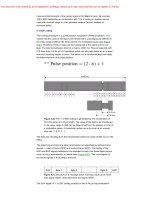
The barcode is a binary code comprising a field of bars and gaps arranged in a
parallel configuration. They are arranged according to a predetermined pattern and
represent data elements that refer to an associated symbol. The sequence, made up of
wide and narrow bars and gaps, can be interpreted numerically and alphanumerically.
It is read by optical laser scanning, i.e. by the different reflection of a laser beam from
the black bars and white gaps (ident, 1996). However, despite being identical in their
physical design, there are considerable differences between the code layouts in the
approximately ten different barcode types currently in use.
The most popular barcode by some margin is the EAN code (European Article
Number), which was designed specifically to fulfil the requirements of the grocery
industry in 1976. The EAN code represents a development of the UPC (Universal
Product Code) from the USA, which was introduced in the USA as early as 1973.
Today, the UPC represents a subset of the EAN code, and is therefore compatible with
it (Virnich and Posten, 1992).
The EAN code is made up of 13 digits: the country identifier, the company identifier,
the manufacturer’s item number and a check digit (Figure 1.3).
In addition to the EAN code, the following barcodes are popular in other industrial
fields (see Figure 1.4):
• Code Codabar: medical/clinical applications, fields with high safety requirements.
• Code 2/5 interleaved: automotive industry, goods storage, pallets, shipping containers and heavy industry.
• Code 39: processing industry, logistics, universities and libraries.
1.1.2
Optical character recognition
Optical character recognition (OCR) was first used in the 1960s. Special fonts were
developed for this application that stylised characters so that they could be read both
Country
identifier
4
0
FRG
Company identifier
1
2
3
4
Company Name
1 Road Name
80001 Munich
5
Manufacturer’s item
number
0
8
1
5
0
CD
9
Chocolate Rabbit
100 g
Figure 1.3 Example of the structure of a barcode in EAN coding
Figure 1.4 This barcode is printed on the back of this book and
contains the ISBN number of the book
1 INTRODUCTION
4
in the normal way by people and automatically by machines. The most important
advantage of OCR systems is the high density of information and the possibility of reading data visually in an emergency (or simply for checking) (Virnich and Posten, 1992).
Today, OCR is used in production, service and administrative fields, and also in
banks for the registration of cheques (personal data, such as name and account number,
is printed on the bottom line of a cheque in OCR type).
However, OCR systems have failed to become universally applicable because of
their high price and the complicated readers that they require in comparison with other
ID procedures.
1.1.3
Biometric procedures
Biometrics is defined as the science of counting and (body) measurement procedures
involving living beings. In the context of identification systems, biometry is the general
term for all procedures that identify people by comparing unmistakable and individual
physical characteristics. In practice, these are fingerprinting and handprinting procedures, voice identification and, less commonly, retina (or iris) identification.
1.1.3.1 Voice identification
Recently, specialised systems have become available to identify individuals using
speaker verification (speaker recognition). In such systems, the user talks into a microphone linked to a computer. This equipment converts the spoken words into digital
signals, which are evaluated by the identification software.
The objective of speaker verification is to check the supposed identity of the person
based upon their voice. This is achieved by checking the speech characteristics of the
speaker against an existing reference pattern. If they correspond, then a reaction can
be initiated (e.g. ‘open door’).
1.1.3.2 Fingerprinting procedures (dactyloscopy)
Criminology has been using fingerprinting procedures for the identification of criminals
since the early twentieth century. This process is based upon the comparison of papillae
and dermal ridges of the fingertips, which can be obtained not only from the finger
itself, but also from objects that the individual in question has touched.
When fingerprinting procedures are used for personal identification, usually for
entrance procedures, the fingertip is placed upon a special reader. The system calculates
a data record from the pattern it has read and compares this with a stored reference
pattern. Modern fingerprint ID systems require less than half a second to recognise
and check a fingerprint. In order to prevent violent frauds, fingerprint ID systems have
even been developed that can detect whether the finger placed on the reader is that of
a living person (Schmidh¨ausler, 1995).
1.1
AUTOMATIC IDENTIFICATION SYSTEMS
1.1.4
5
Smart cards
A smart card is an electronic data storage system, possibly with additional computing
capacity (microprocessor card), which — for convenience — is incorporated into a
plastic card the size of a credit card. The first smart cards in the form of prepaid
telephone smart cards were launched in 1984. Smart cards are placed in a reader,
which makes a galvanic connection to the contact surfaces of the smart card using
contact springs. The smart card is supplied with energy and a clock pulse from the
reader via the contact surfaces. Data transfer between the reader and the card takes
place using a bidirectional serial interface (I/O port). It is possible to differentiate
between two basic types of smart card based upon their internal functionality: the
memory card and the microprocessor card.
One of the primary advantages of the smart card is the fact that the data stored
on it can be protected against undesired (read) access and manipulation. Smart cards
make all services that relate to information or financial transactions simpler, safer and
cheaper. For this reason, 200 million smart cards were issued worldwide in 1992. In
1995 this figure had risen to 600 million, of which 500 million were memory cards and
100 million were microprocessor cards. The smart card market therefore represents
one of the fastest growing subsectors of the microelectronics industry.
One disadvantage of contact-based smart cards is the vulnerability of the contacts
to wear, corrosion and dirt. Readers that are used frequently are expensive to maintain
due to their tendency to malfunction. In addition, readers that are accessible to the
public (telephone boxes) cannot be protected against vandalism.
1.1.4.1 Memory cards
In memory cards the memory — usually an EEPROM — is accessed using a sequential logic (state machine) (Figure 1.5). It is also possible to incorporate simple security
algorithms, e.g. stream ciphering, using this system. The functionality of the memory
card in question is usually optimised for a specific application. Flexibility of application is highly limited but, on the positive side, memory cards are very cost effective.
For this reason, memory cards are predominantly used in price sensitive, large-scale
Vcc
GND
RST
Vpp
CLK
I/O
Figure 1.5
Address and
Security Logic
EEPROM
ROM
Typical architecture of a memory card with security logic
1 INTRODUCTION
6
applications (Rankl and Effing, 1996). One example of this is the national insurance
card used by the state pension system in Germany (Lemme, 1993).
1.1.4.2 Microprocessor cards
As the name suggests, microprocessor cards contain a microprocessor, which is connected to a segmented memory (ROM, RAM and EEPROM segments).
The mask programmed ROM incorporates an operating system (higher programme
code) for the microprocessor and is inserted during chip manufacture. The contents of
the ROM are determined during manufacturing, are identical for all microchips from
the same production batch, and cannot be overwritten.
The chip’s EEPROM contains application data and application-related programme
code. Reading from or writing to this memory area is controlled by the operating
system.
The RAM is the microprocessor’s temporary working memory. Data stored in the
RAM are lost when the supply voltage is disconnected (Figure 1.6).
Microprocessor cards are very flexible. In modern smart card systems it is also
possible to integrate different applications in a single card (multi-application). The
application-specific parts of the programme are not loaded into the EEPROM until
after manufacture and can be initiated via the operating system.
Microprocessor cards are primarily used in security sensitive applications. Examples
are smart cards for GSM mobile phones and the new EC (electronic cash) cards. The
option of programming the microprocessor cards also facilitates rapid adaptation to
new applications (Rankl and Effing, 1996).
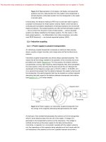
1.1.5 RFID systems
RFID systems are closely related to the smart cards described above. Like smart card
systems, data is stored on an electronic data-carrying device — the transponder. However, unlike the smart card, the power supply to the data-carrying device and the
data exchange between the data-carrying device and the reader are achieved without the use of galvanic contacts, using instead magnetic or electromagnetic fields. The
Vcc
GND
RST
Vpp
CLK
I/O
Figure 1.6
CPU
RAM
ROM
(operating
system)
EEPROM
(application
data)
Typical architecture of a microprocessor card
1.3
COMPONENTS OF AN RFID SYSTEM
7
underlying technical procedure is drawn from the fields of radio and radar engineering.
The abbreviation RFID stands for radio frequency identification, i.e. information carried by radio waves. Due to the numerous advantages of RFID systems compared with
other identification systems, RFID systems are now beginning to conquer new mass
markets. One example is the use of contactless smart cards as tickets for short-distance
public transport.
1.2
A Comparison of Different ID Systems
A comparison between the identification systems described above highlights the
strengths and weakness of RFID in relation to other systems (Table 1.1). Here too, there
is a close relationship between contact-based smart cards and RFID systems; however,
the latter circumvents all the disadvantages related to faulty contacting (sabotage, dirt,
unidirectional insertion, time consuming insertion, etc.).
1.3
Components of an RFID System
An RFID system is always made up of two components (Figure 1.7):
• the transponder, which is located on the object to be identified;
• the interrogator or reader, which, depending upon the design and the technology
used, may be a read or write/read device (in this book — in accordance with
normal colloquial usage — the data capture device is always referred to as the
reader, regardless of whether it can only read data or is also capable of writing).
A practical example is shown in Figure 1.8.
A reader typically contains a radio frequency module (transmitter and receiver), a
control unit and a coupling element to the transponder. In addition, many readers are
fitted with an additional interface (RS 232, RS 485, etc.) to enable them to forward
the data received to another system (PC, robot control system, etc.).
The transponder, which represents the actual data-carrying device of an RFID system, normally consists of a coupling element and an electronic microchip (Figure 1.9).
Data
RFID reader
Clock
Contactless
data carrier =
transponder
Energy
Application
Figure 1.7
Coupling element
(coil, microwave antenna)
The reader and transponder are the main components of every RFID system
Low
∼3 s
<1 cm
Scanner
Possible∗
(audio
tape)
Very low
>5 s
0–50 cm
None
—
Very high
—
—
—
High
Expensive
Simple
—
Voice recog.
Very low
>5–10 s
Direct
contact∗∗
Impossible
None
—
Very high
Possible
—
—
High
Expensive
Difficult
—
Biometry
Low
∼4 s
Direct contact
Medium
(contacts)
Impossible
Contacts
Low
16–64 k
Very high
Good
Impossible
Possible
(contacts)
—
Unidirectional
Smart
card
The danger of ‘Replay’ can be reduced by selecting the text to be spoken using a random generator, because the text that must be spoken is not known in advance.
This only applies for fingerprint ID. In the case of retina or iris evaluation direct contact is not necessary or possible.
∗∗
∗
Low
∼4 s
0–50 cm
Reading speed (including
handling of data carrier)
Maximum distance between
data carrier and reader
Slight
Low
Low
Slight
Limited
Medium
Limited
Very low
Unauthorised
copying/modification
Total failure
Low
Total failure
Low
Influence of (opt.) covering
Influence of direction and
position
Degradation/wear
Purchase cost/reading
electronics
Operating costs (e.g. printer)
1–100
Low
Good
Simple
Very high
OCR
1–100
Low
Good
Limited
Very high
Barcode
Typical data quantity (bytes)
Data density
Machine readability
Readability by people
Influence of dirt/damp
System parameters
Table 1.1 Comparison of different RFID systems showing their advantages and disadvantages
Very fast
∼0.5 s
0–5-m,
microwave
Impossible
None
No influence
Medium
No influence
No influence
16–64 k
Very high
Good
Impossible
No influence
RFID
systems
8
1 INTRODUCTION