Tài liệu Mastering Revit Architecture 2008_ Part 9 pdf
Bạn đang xem bản rút gọn của tài liệu. Xem và tải ngay bản đầy đủ của tài liệu tại đây (2.23 MB, 29 trang )
Chapter 8
From Conceptual Mass to a
Real Building
In this chapter, we’ll describe the use of an early conceptual mass model to help you understand
program fitness and early feasibility studies. You’ll see how easy it is to convert a massing study,
whether done within Revit or imported from another application, into building elements such as
walls, floors, and roofs. The premise of a BIM approach to design is that a fluid workflow can be
maintained as you move from early concept models into design development, and eventual construction
documentation, all the while maintaining the same underlying geometry and design intent. Revit
provides specifically designed tools that accommodate early massing model studies for program
validation and feasibility studies, which can then be quickly converted to real building elements.
You’ll acquire the following skills in this chapter:
◆
Leveraging a massing study for program validation and early feasibility studies
◆
Converting a mass into a building using the Building Maker tools
◆
Importing files from other sources when working on massing
Conceptual Design and Early Studies
A project usually starts with a very rough conceptualization of first ideas in which the architect’s
mind wanders between the creativity of fantasy and the reality of customer needs, merged with the
influence of the genius loci.
Conceptual designs are the first graphical words an architect exchanges with a client to get
approval for the architect’s first thoughts and sense the temperature of the client’s taste. When the
initial idea is approved, the architect continues in the next stage of development of their design and
makes more developed studies supported by concrete measurements and numbers that show the
applicability of the design and its feasibility.
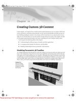
We’ll review how this process can be done using Revit. Figure 8.1 shows an example of a very
early massing study using Revit that has the semblance of a building. Let’s walk through how this
workflow is supported.
44831.book Page 229 Friday, October 12, 2007 12:31 AM
Please purchase PDF Split-Merge on www.verypdf.com to remove this watermark.
230
CHAPTER 8
FROM CONCEPTUAL MASS TO A REAL BUILDING
Figure 8.1
Massing study model
Getting Site Data and Building the Context
A project usually starts with a client’s wish, vision, and hopes described during a conversation with the
architect. A list of program requirements is compiled, listing the types of spaces the building will have
and its rough area. The architect then starts gathering information and data about the site—aerial
photos, photos of the site and context, site-survey files with land information, and building footprints
and blocks. Using site analysis, program requirements, and creativity, the architect proceeds to study
what shape and size building fits best. Variations of the design are studied, analyzed, critiqued, and
presented to the client.
Getting site data into the digital model is the first step in moving from loose napkin sketches to
a real project. By importing DWG/DGN site information into Revit, you’ll have an underlay from
which to work. (For small projects, this can also be a scanned image of a hand-drawn site situation.)
CAD drawings with site information usually come with a rich amount of information that needs to
be culled. Using the Visibility/Graphic Overrides dialog, you can hide unnecessary layers to make
the drawings more legible. Setting the correct scale and orientation of the site relative to the build-
ing will be the most critical beginning steps and should be done during the import of the site file.
44831.book Page 230 Friday, October 12, 2007 12:31 AM
Please purchase PDF Split-Merge on www.verypdf.com to remove this watermark.
CONCEPTUAL DESIGN AND EARLY STUDIES
231
Scale
In the Import dialog, setting the units to Automatic usually works well if the CAD file was drawn
at 1:1 inch scale. If the drawing was scaled, you may find that the scale of the imported file is incor-
rect, and you need to re-import the file and set the scale units manually to get useful results.
Orientation
The next step is to deal with the orientation of the imported site plan. Maps are usually created so
that north is always at the top, and that is how site information should be displayed in final docu-
ments. When you’re working on developing a site plan, you’ll prefer to work in a way that is most
comfortable for you, so the site is oriented parallel to your computer screen—not to true north.
Orienting a Site Plan to Fit Your Screen
Suppose you’re starting your design study, and you open a site plan view to import the CAD file with the
site. An imported CAD drawing usually comes in its original coordinates’ orientation, with north/south
in the vertical axis:
44831.book Page 231 Friday, October 12, 2007 12:31 AM
Please purchase PDF Split-Merge on www.verypdf.com to remove this watermark.
232
CHAPTER 8
FROM CONCEPTUAL MASS TO A REAL BUILDING
Positioning Imported Files Relative to the Revit Project
You can choose to automatically place or manually place an import. With Automatically Place
(under the “Positioning” group in the Import dialog) you have the following options:
Center-to-center
aligns the 3D center points of both models.
Origin-to-origin
places the world origin of the linked file at the Revit model’s origin point. If the
linked model was created far from the origin point, linking with this option may put the linked
file far away from the main model.
If you open the view’s properties, you’ll notice that the Orientation
parameter indicates Project North:
By default, the orientation of a view is set to Project North. By changing the Orientation parameter to
True North and rotating the True North setting, you can work in a comfortably oriented plan relative to
your screen.
In the View Properties change Orientation to True North, and rotate true north using Tools
Project
Position/Orientation
Rotate True North. A rotation control appears in the view. Rotate to an angle
best suited to work on. Note that this does not mean you’ve rotated the project but rather the world.
This procedure is more than enough if you don’t intend to send information back to the person you
received the file from. However, if you’re collaborating with a civil engineer and need to send back the
building footprint or an early mass study, you need to establish a connection between the two files so
they have the same coordinates. This can be achieved using the Linking method as well as the Acquire
Coordinates functionality.
44831.book Page 232 Friday, October 12, 2007 12:31 AM
Please purchase PDF Split-Merge on www.verypdf.com to remove this watermark.
CONCEPTUAL DESIGN AND EARLY STUDIES
233
By shared coordinates
places a linked file geometry according to the shared coordinate system
created between the two files (this is available only if you’re linking files). If no shared coordi-
nate file has been created, Revit alerts you. The Shared Coordinates settings can be found in the
Tools drop-down menu; you have the following options:
Acquire Coordinates
allows you to take the coordinates of the linked file into the host
model. There is no change to the host model’s internal coordinates; however, the host model
acquires the true north of the linked model and its Origin setting.
Publish Coordinates
allows you to publish the Origin and True North settings to your
linked model. Revit understands that there may be other things in your linked file and you
may not want this to be a global change to the linked file. An additional dialog appears that
gives you the option to name separate locations for each set of coordinates.
Specify Coordinates at a Point
allows you to manually key in x, y, and z coordinates relative
to the origin point or define where you want your 0,0,0 point to be.
Report Shared Coordinates
shows the E/W (east/west) (x), N/S (north/south) (y), and
elevation (z) coordinates of any point in the model.
You can import a CAD file so that it appears in all views, or you can import it in the Current view
only. You will find these options under the Import or Link group box. Remember that for topog-
raphy files, you should NOT select the “Current View only” option because you will not be able to
convert the imported file into topography.
If you forgot this rule, we advise that you delete the import and re-import, making sure that the
Current View option is NOT checked. You will most probably not want the Site file to be visible in
all other views, so you can turn its visibility on in the other views later.
Building the 3D Context
After positioning the imported CAD file in your site plan and reorienting it to True north, you can
start building the environment in 3D using the massing tools. The base shapes of buildings in the
CAD file can be used to quickly generate a massing model of the surrounding site. Use photos or
actual data to establish building heights.
To make a 3D study of the surrounding site, use the Create Mass feature
and begin developing
solids out of the existing geometry:
1.
From the Massing tab in the Design bar, select Create Mass. Give the mass a name, such as
context buildings
.
2.
Select the Extrusion solid form, and switch from Draw to Pick method using the Options bar.
Select lines in the imported file to create the base sketches.
3.
Change the Height of each mass to match the real-world conditions.
4.
Give each massing a material that suits your graphic needs. A neutral gray or white is common.
Figures 8.2–8.5 show the use of massing to create abstract forms that represent the context.
44831.book Page 233 Friday, October 12, 2007 12:31 AM
Please purchase PDF Split-Merge on www.verypdf.com to remove this watermark.
234
CHAPTER 8
FROM CONCEPTUAL MASS TO A REAL BUILDING
Figure 8.2
Massing used to add
surrounding context
buildings
Figure 8.3
Massing used for
abstract contextual
representation
I
MAGE
COURTESY
OF
K
UBIK
-N
EMETH
-V
LKOVIC
44831.book Page 234 Friday, October 12, 2007 12:31 AM
Please purchase PDF Split-Merge on www.verypdf.com to remove this watermark.
CONCEPTUAL DESIGN AND EARLY STUDIES
235
Figure 8.4
Massing used to
model existing
buildings on site
Figure 8.5
Massing used to create
an initial form
Program Check and Feasibility
Many of the activities in early design revolve around exploring the commercial viability of the site
and figuring out the right mix of uses (for example, residential versus office versus retail). All these
uses have different economic returns. Zoning regulations can be complicated in how they allow dif-
ferent amounts of total development based on the mix ratio. In essence, two numbers govern almost
all urban property: Floor Area Ratio (FAR) and Lot Coverage Ratio (LCR). FAR is a number that
says how many multiples of the site area the building area can be. LCR specifies the percentage area
of the site that can be covered by the building footprint. Usually the architect is required to maxi-
mize the FAR by determining the right mix of uses placed at the right location on the site.
Image courtesy of Felipe Manrique Diaz, Uruguay
Image courtesy of HOK
44831.book Page 235 Friday, October 12, 2007 12:31 AM
Please purchase PDF Split-Merge on www.verypdf.com to remove this watermark.
236
CHAPTER 8
FROM CONCEPTUAL MASS TO A REAL BUILDING
At this stage, the problem is not only about forms or shapes but about the program, construction
costs, and rents and the functional distribution on the site horizontally and vertically. The architect
usually attempts to determine what physical forms, in what location, with what use, will provide
the best economic return to the owner. This study then needs to be consolidated and documented.
While studying this problem, the architect may generate tens if not hundreds of slightly different
alternatives for numerical comparative purposes. A few of the most promising are then developed
further for presentation purposes.
At early stages in design, you need to check the program and how well you fit into it. Programs
can be less or more precise, depending on the client and the task in question. It can be as bold as
15,000 sq. ft. (4570 sq. meters) offices, 40,000 sq. ft. (12,200 sq. meters) hotel space, and 20,000 sq. ft.
(6100 sq. meters) retail space for a bigger complex; or it can be an exact number of rooms and spaces
when working on one building. Figure 8.6 shows an early massing study annotated to show usage
and areas.
Figure 8.6
Early study docu-
menting maximum
allowed heights and
total square footage of
a proposed solution
The architect is constantly thinking about architectural expression, fitting in the site, and accom-
modating the program. They’re also evaluating whether the client’s requirements can fit the allowed
buildable area and height of the site, zoning regulations, land uses, traffic requirements (they usu-
ally always want more), and information about the number of parking spaces and other support
functionalities. This phase of the project can also involve shadow studies and energy modeling, as
discussed in Chapter 14.
The next step is to propose multiple solutions to the client, so proposals with different mixes of
functions and spatial solutions can be reviewed and analyzed. This is where the Design Options
tools you’ll learn about in Chapter 9 come in handy.
I
MAGE
COURTESY
OF
K
UBIK
-N
EMETH
-V
LKOVIC
44831.book Page 236 Friday, October 12, 2007 12:31 AM
Please purchase PDF Split-Merge on www.verypdf.com to remove this watermark.
CONCEPTUAL DESIGN AND EARLY STUDIES
237
Creating Multiple Massing Design Options
Here is a suggested workflow based on a real-world use case.
The architectural firm Gensler created an option set with three options, each with a distinct name. They
duplicated 3D views and schedules to document project information early on. In each view, the Visibility/
Graphic Overrides were set to display each option (one set to Option 1, another to Option 2, and the third
to Option 3). Doing so not only visually described the new option but also presented the data behind
each design.
44831.book Page 237 Friday, October 12, 2007 12:31 AM
Please purchase PDF Split-Merge on www.verypdf.com to remove this watermark.
238
CHAPTER 8
FROM CONCEPTUAL MASS TO A REAL BUILDING
Building Maker
After several iterations and tweaking, the client makes up their mind. One of the solutions is selected
to go forward, and you’re ready to convert that early mass into a real building. Here is where the
Building Maker tools come into play. With these tools, you can get more detailed information about
the model by attaching walls, floors, and roofs to the massing shapes.
This approach has two major advantages over traditional 3D systems:
◆
The need to re-create the digital data from scratch is eliminated.
◆
An established connection exists between the building elements made by referencing the mass
and the mass itself, so the massing design can iterate and update the building elements.
The nice thing about the Building Maker workflow is that it also supports the import of geom-
etry from tools such as Rhino, 3ds Max, and SketchUp into mass shapes, to which you can then
attach wall, floors, and roofs.
Chapter 6 discussed the principles of modeling, and Chapter 7 analyzed the bases of the mass-
ing tools for creation of massing studies. You should have a good understanding of how to create
a mass element or an entire mass study. We’ll now focus on the second group of tools located in the
Massing tab of the Design bar: the so-called Building Maker tools.
Let’s get an overview the available tools and then examine their real-life application.
44831.book Page 238 Friday, October 12, 2007 12:31 AM
Please purchase PDF Split-Merge on www.verypdf.com to remove this watermark.
CONCEPTUAL DESIGN AND EARLY STUDIES
239
Floor Area Faces
The first tool you should know about isn’t visible in the Massing tab. It’s the Floor Area tool, which
is designed for getting early square-footage take-offs from the massing. This tool appears in the
Options bar whenever a mass that you created is selected.
Assuming you’ve created a mass study in which you define the basic volumes and shapes that
will form your building or complex of buildings, you’re ready to start setting up levels. Depending
of the type of building you’re making, code regulations, and functional usage, you can begin to lay
out levels for the building. Let’s say the maximum height is 90´´ (22m), and your building is a hotel,
which will usually have a 12´ (3m) floor-to-floor height. In that case, you can get approximately
seven levels.
From any elevation view, add levels using the Level tool. It’s obviously much easier to copy a
level graphically using the Multiple Copy or Array command; however, with that method you
won’t create actual floor plans for each of the levels. If that’s OK with you, go ahead. If not, you can
either use the Level tool and draw each Level or use the copy method to create levels but then create
floor plans from those levels by using the View/Floor Plan tool and selecting which levels should
have a floor plan view associated with them.
Click the Floor Area Faces button when the mass is selected. You’ll get a list of all levels in the
project. If you check all levels, a floor area will be calculated for each level. If you want to skip a
level because of double room height, for example, don’t check that level. You can do this for all
masses at the same time or separately for each volume.
When you OK the level selection, your mass is sliced by floor (see Figure 8.7).
Imagine that the other masses are for the conference center and parking structures, and apply
the same concept. Add levels appropriate for each structure, then select each mass, click Floor Area
Faces, and choose which levels you want to slice up the mass.
You now understand why the Level tool is handy on the Massing Design bar. Revit is fantastic
because you can add, delete, and reshuffle levels at any moment in your project development with-
out needing to redo work or losing any invested work. This
slicing
of volumes doesn’t just visually
help you understand the number of floors and divisions—it also calculates the floor area of the
mass element in question and allows you to schedule the values (Figure 8.8).
Verifying Your Design and Its Fit within the Defined Program
You can schedule the parameters and values of the masses similar to how you schedule other Revit
elements. In the earliest phase of the project, you’ll probably want to schedule the functional zones.
To create an understandable schedule, it’s a good idea to give the mass elements you created names
according to their function—Hotel Rooms, Conferences, Parking, Restaurants, and so on—and
assign them different colors (materials) so it’s easy to visually represent the data. If you need to
rename the mass element once it is created you can do that from the project Browser—find the Mass
Element in question and rename. As mentioned in Chapter 7, you can also add project parameters
to the mass elements, such as Public or Private Space, Department, and so on. If you wish to tag
those new parameters so that they are shown in the Mass Tag, you must make them shared param-
eters and add them in the Massing Tag family. See Chapter 15 for more on shared parameters.
Out of the box, the mass elements in Revit can report the following properties:
◆
Gross Floor Area
◆
Gross Surface
◆
Gross Volume
44831.book Page 239 Friday, October 12, 2007 12:31 AM
Please purchase PDF Split-Merge on www.verypdf.com to remove this watermark.