Tài liệu Mastering Revit Architecture 2008_ Part 11 pdf
Bạn đang xem bản rút gọn của tài liệu. Xem và tải ngay bản đầy đủ của tài liệu tại đây (1.61 MB, 29 trang )
Chapter 10
Creating Custom 3D Content
In this chapter, we’ll explore how to build custom model elements for use in a project. We’ll look
at how parametric constraints and parameters can be used to build flexible and time-saving con-
tent. Building intelligent content is a key feature of Revit and deserves an entire book in its own
right, but we will introduce you to some useful concepts and get you going. This chapter will take
you through fundamental principles and some compelling use cases using the family editor.
You’ll acquire the following skills in this chapter:
◆
Understanding the different types of families and their application
◆
Leveraging nested families for efficiency and flexibility
◆
Building relationships between parameters with formulas
Modeling Parametric 3D Families
As a design progresses from the generic to the more refined, you’ll need to add more detail and real-
ism to your components. This process involves more faithfully representing what will be built and
will require you to start building your own families. Although many types of families are provided
out of the box or can be downloaded from websites such as the Revit web library or
revitcity.com
,
you’ll inevitably reach a point where your design intent isn’t matched by existing content (Figure 10.1).
This is when you’ll need to dig into the Family Editor and create new building components.
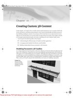
Figure 10.1
This sun-shading
element was imple-
mented as a custom
Revit family.
44831.book Page 279 Friday, October 12, 2007 12:31 AM
Please purchase PDF Split-Merge on www.verypdf.com to remove this watermark.
280
CHAPTER 10
CREATING CUSTOM 3D CONTENT
Up to now, we’ve covered many of the basic principles of families, including family categories,
form making, and constraints; but we haven’t put this into practice beyond some simple shapes. In
the following sections, we’ll look at more advanced techniques used to make parametric families
with embedded intelligent behaviors.
Choosing the Right Family Template
Every family belongs to a category, making it important to assign new families correctly so they can
be controlled logically when loaded into a project. Revit provides a series of pre-made templates
(Figure 10.2) for most families.
Figure 10.2
Premade model
family templates
When you decide to create an element on your own you need to select the correct template.
These premade templates are time savers, because they already have the right category assigned,
provide the most important reference planes that drive the behavior and geometry, and in some cases
include text notes to help explain how the family will work in the context of a project. Figure 10.3
shows a window template file, which includes text indicating the exterior/interior of the wall;
parametric dimensions for width, sill height, and opening height; and a sample host wall.
The reference planes that appear in the family environment are the essential bones of any family.
They establish the critical dimensional rules for the family, define the origin, and provide refer-
ences that can be dimensioned to. All starting templates provide at least two reference planes to
start with, because without reference planes, you can’t make parametric content or dimension it in
the project.
Types of Families
For model-based families, there are two high-level types: 2D and 3D. 2D families are used for making
2D details of the model, and 3D families are for making 3D geometric representations. Note that 3D
families can contain nested 2D elements as a way to embed details directly into content.
For 2D families, you can make standard detail components and line-based (2-pick) detail com-
ponents. 3D family types include various host-based types (floor, wall, roof, and ceiling), profiles,
line based, work-plane based, and generic model. Depending on which template you use, you’ll get
different behavior in the model. To better understand what that means, let’s drill deeper.
44831.book Page 280 Friday, October 12, 2007 12:31 AM
Please purchase PDF Split-Merge on www.verypdf.com to remove this watermark.
TYPES OF FAMILIES
281
Figure 10.3
Plan, elevation, and
3D view of a template
for windows. Text
notes, reference
planes, and dimen-
sions have been preset.
44831.book Page 281 Friday, October 12, 2007 12:31 AM
Please purchase PDF Split-Merge on www.verypdf.com to remove this watermark.
282
CHAPTER 10
CREATING CUSTOM 3D CONTENT
Host-Based Families
Windows, doors, skylights, and lighting fixtures are all discretely manufactured objects, but they
have something in common: They’re installed into something else. Without the wall, ceiling, or
mounting surface, the object has no place to ground itself in a typical building project. For these
types of elements, Revit provides host-based families and templates. When you need content to
have an explicit relationship with a wall, floor, or roof, then a host-based family is absolutely the
way to go. These are the most common types of families used in Revit, and include components
such as doors, windows, skylights, solar panels, light fixtures, and balusters. Assuming you’ve
placed some windows and doors in a Revit project, the benefits and behaviors of host-based
families need not be covered here. Figure 10.4 shows several examples.
Figure 10.4
Examples of host-
based families
When you’re making a new family, first think from a category point of view: What am I making?
Then, use an appropriate template as a starting point. For example, if you need to make a new win-
dow, start with the
Window.rft
template.
Wall-based door Wall-based window
Roof-based skylight Ceiling-based lighting fixture
44831.book Page 282 Friday, October 12, 2007 12:31 AM
Please purchase PDF Split-Merge on www.verypdf.com to remove this watermark.
TYPES OF FAMILIES
283
Windows and doors don’t exist in the model in isolated, abstract form, but are always hosted by
a wall. This is why you see a sample host element (a small wall, roof, or floor) when you open a
host-based template. The sample host is used to help you construct the family so it behaves prop-
erly in the model—to give you a context in order to build the family so it correctly relates to wall
thickness.
Note that the host that exists in the family template (such as the wall in the window template)
isn’t loaded in the project when you load the window—it’s present in the Family Editor only as a
reference to help you understand how the window will work when loaded into a project. Only the
geometry and reference planes that you create end up in your project.
Profile Families
Many architectural details have distinct cross sections that run in a linear fashion. Geometrically, these
details are constructed by extruding that profile along a path, which maps to how many of the elements
are physically manufactured. Baseboards, cornices, handrails, and mullions are all examples:
Revit provides special templates designed for elements like these. To create one of these ele-
ments, you choose to make a profile family. Then, sketching with 2D lines, you define the shape of
the profile cross section. Like many sketches in Revit, the profile must be made of
a single closed loop
of lines—multiple loops will lead to errors downstream. For example, if you loaded a mullion pro-
file like that shown in Figure 10.5 and then tried to use it in a mullion family, you’d get a warning
message. Delete the inner loop of lines to get the mullion to work properly.
Figure 10.5
Invalid profile:
Profiles with more
than one loop won’t
work in a project.
How do you make something like the shape shown in Figure 10.5? Although you can’t have
multiple loops in the profile family, you can import a detail component into the profile family, as
there is no penalty for having multiple loops of lines in the detail component. To control when this
44831.book Page 283 Friday, October 12, 2007 12:31 AM
Please purchase PDF Split-Merge on www.verypdf.com to remove this watermark.
284
CHAPTER 10
CREATING CUSTOM 3D CONTENT
level of detail is visible in the model, you can set the visibility of the detail component so it appears
only at fine levels of detail. Continuing with the mullion example (Figure 10.6), take these steps:
1.
Load a complex detail component derived from a manufacturer into the mullion profile
family.
2.
Trace the loaded component with a single loop of lines.
3.
Set the options in the “Family element visibility settings” dialog to show the detail only in
fine views.
Figure 10.6
On the left is the
profile sketch, on
the right a detail
component.
4.
Load the family into the project.
5.
From the Project Browser, locate the rectangular mullion profile and duplicate it. Open the
Type Properties dialog, and assign the new profile to the mullion family (Figure 10.7).
Figure 10.7
Choose the profile
from the mullion’s
Type Properties.
Profile
sketch lines
Detail
component
44831.book Page 284 Friday, October 12, 2007 12:31 AM
Please purchase PDF Split-Merge on www.verypdf.com to remove this watermark.
TYPES OF FAMILIES
285
Once a profile is loaded into Revit, it doesn’t take 3D form until it’s assigned to system families
such as rails, mullions, wall sweeps, and gutters. To do this, open the Type Properties dialog of any
of these families and assign the profile to the family. You can use a 2D profile in the definition of a
wall as a precast parapet cap, as shown in Figure 10.8.
Figure 10.8
Assigning a profile to a
system family
Many companies that sell finish moulding provide 2D CAD drawings that you can import
directly into a Revit profile family. This is a great time saver and will keep you from having to draw
complex profiles from scratch.
Profiles can be used for many different purposes. To accommodate more specific behavior
as well as categorization, five different profile family templates are available
:
Profile.rft
,
Profile-Rail.rft
,
Profile-Reveal.rft
,
Profile-Stair Nosing.rft
, and
Wall Sweep
Profile.rft
. Be careful to select the correct one, because Revit looks only for specific profiles
depending on what you’re making. For example, a mullion family won’t let you choose a wall-
sweep profile; only mullion profiles will show up in the list.
2D Line-Based Families
Not all elements need to be modeled in 3D; some are represented using 2D detail drawings. Most
details can be drawn using lines and filled regions, but these are inherently difficult to maintain and
reuse. For details that are likely to be used in other drawings or projects, you should create detail
families. With Revit, you can make stand-alone detail components or line-based families. The line-
based family is great for making elements where length is the primary variable.
The 2D line-based template (
Detail Component line based.rft
) can be useful. These families
let you draw a detail element as if you’re drawing lines, but the component can contain as many
lines and filled regions as you want. For example, you can draw a detail component that represents
plywood (lines + wood hatch) with two clicks of the mouse.
3D Line-Based Families
Just like the 2D drafting line-based families, you can make 3D line-based families. For these families,
use the template
Generic Model line based.rft
. Examples where you need such 3D line-based
44831.book Page 285 Friday, October 12, 2007 12:31 AM
Please purchase PDF Split-Merge on www.verypdf.com to remove this watermark.
286
CHAPTER 10
CREATING CUSTOM 3D CONTENT
families are molding details, sun shades, grating, and any other elements that have length as their
primary variable. Figure 10.9 shows a 3D chair family that adds chairs as the family is made longer.
Figure 10.9
3D line-based
chair family
With two clicks of the mouse, you can quickly add rich 3D content to your model. Figure10.10
shows a sun-shade example. The brackets at the left and right side were modeled in the family
using solid extrusions and constrained to the left and right reference planes. The blades were mod-
eled as sweeps between the two horizontal reference planes, using a profile. When placed in the
model, the sun shade can be stretched dynamically.
Making a Plywood Line-Based Family
To make a plywood line-based detail, you can use the line-based detail template. In the line-based fam-
ily template, you create a filled region between the left and right reference planes and assign a plywood
fill pattern to the region. As long as the left and right lines of the filled region are coincident with
the reference planes, they will follow the planes when the family is placed in a project, and drawn. The
cross-sectional dimension of the filled region can be driven by a Thickness parameter, which is set to
3
⁄
4
˝
and can later be modified if you need new types:
When the plywood family is loaded into the project, you can make a symbolic 2D plywood representa-
tion with two clicks that define the length. Once you’ve placed the plywood, you can reselect it and drag
either end using the blue grips to stretch the detail. Compared to using a filled region in the project, this
method provides parametric constraints, reusability, and incredible ease of use.
44831.book Page 286 Friday, October 12, 2007 12:31 AM
Please purchase PDF Split-Merge on www.verypdf.com to remove this watermark.
TYPES OF FAMILIES
287
Figure 10.10
3D line-based
sun shade family
Work Plane– and Face-Based Families
For elements that need the flexibility to be placed on any model face, such as electrical outlets,
signage, or coffee pots, there are work plane– and face-based families. These families attach to any
surface of the model during placement; you can later rehost them to any other surface if need be.
Any time you have a component that needs to be installed on multiple types of hosts, think of
making the family face based.
Face-Based Families
You create face-based families with the template
Generic Model face based.rft
.
When you
open the template, you see an abstract host surface on which you can model your family. When you
load your family into your project, the host surface in the family maps to whatever face you choose
in the project, and your family reorients to sit on that face automatically. The face you choose can
be anything from another family to geometry of a linked file. An example of a face-based family is
an HVAC supply register, which you need to be able to place on walls, ceilings, or even floors.
Figure 10.11 shows another application of a face-based component, where the curved surface
doesn’t have a work plane.
Figure 10.11
A sign is an example of
a face-based family.
44831.book Page 287 Friday, October 12, 2007 12:31 AM
Please purchase PDF Split-Merge on www.verypdf.com to remove this watermark.
288
CHAPTER 10
CREATING CUSTOM 3D CONTENT
Work Plane–Based Families
Work plane–based families are placed on the active work plane of the current view. Every view has
an active work plane that you can manipulate using the Work Plane tool; see Chapter 6.
Be sure to give the family an appropriate category before loading it so you can control its visi-
bility and graphics.
Rich Photorealistic Content (RPC) Families
When you’re rendering a view, it’s possible to substitute real model geometry (the family) for highly
photorealistic images (such as Archvision content, available at
/>
). For
example, a simplified stick figure can turn into a real-looking person when the view is rendered
(Figure 10.12).
Figure 10.12
Left: Entourage family,
non-rendered. Right:
Same family when
rendered
This can be a cool feature when you’re rendering, and it makes rendering faster because there
is no complex geometry to render. You can create plants, cars, and people using these families.
Assigning a Rendering Appearance
RPC families are specialized and have specific behavior when rendered. In addition to the 3D and
2D representation that you normally add to a family, you can also assign a rendering appearance
to the family. This appearance shows up only when you raytrace a 3D view.
You create RPC families using the template
RPC Family.rft
. RPC appearances can only be
added to the Entourage and Planting families. When the family is set to either of these categories,
a Rendering Type parameter is enabled in the Settings
Family Category and Parameters dialog. RPC
families in these categories have additional type parameters (located in the Family Types dialog; see
Figure 10.13) to control the associated RPC file used when the family is rendered in a project, along
with specific properties. In Figure 10.14, RPC properties of a car allow you to specify the license
plate and window tinting!
Figure 10.13
RPC parameters in the
Family Types dialog
44831.book Page 288 Friday, October 12, 2007 12:31 AM
Please purchase PDF Split-Merge on www.verypdf.com to remove this watermark.
TYPES OF FAMILIES
289
Figure 10.14
RPC Properties dialog
for a car family
Detail Component Families
As you’ll see in Chapters 17 and 18, a typical workflow to complete a Construction Document set
involves enriching the model with 2D details in detail views. These detail elements typically depict
cross sections or elevation views of elements that don’t need to be modeled in full 3D (to do so
would only bog down the model and not add much value). For this use case, you can use detail-
component families to add detail to model or drafting views; these details are visible only in the
view in which they’re placed. Examples include blocking, studs, steel sections, bolts, flashing, and
so on:
Detail components can contain lines, filled regions, masking regions, symbols, and other detail
components. Detail components are meant to represent real building components and assemblies,
so they scale with the model when the view scale is changed. To create a new detail component
family, use
Detail Component line based.rft
or
Detail Component.rft
.
Generic 3D Families
If you can’t find templates for element types, use generic families. These don’t relate to any specific
host but are rather used for free-standing components. Generic families allow you to create content
such as fireplaces or other hard-to-categorize objects. These families have a relationship to the level
in which they’re placed but are otherwise free to move around the model and aren’t connected to
any host objects.
Many generic templates have been pre-made for you with the appropriate category selected.
Examples include
Furniture.rft
,
Furniture Systems.rft
,
Mechanical Equipment.rft
,
and
Plumbing fixture.rft
, to name a few.
44831.book Page 289 Friday, October 12, 2007 12:31 AM
Please purchase PDF Split-Merge on www.verypdf.com to remove this watermark.